Transcription
Transformer Loading & Thermal Design Considerations46TH Annual UTA TSDOSSEPTEMBER 2013 SPX TRANSFORMER SOLUTIONS, INC.
Transformer Loading &Thermal Design ConsiderationsYOUR PRESENTER:John PruenteDirector of Engineering Technical SupportSPX Transformer Solutions, Inc.Office: 214-637-4434Cell: 817-300-6843John.Pruente@spx.com SPX TRANSFORMER SOLUTIONS, INC.John joined SPX Transformer Solutions inJune 1999, where his engineering and technicalsupport responsibility spans the Serviceand Components Division. Prior to SPX, hewas employed by Duke Energy, where he wasresponsible for all aspects of transformermaintenance, development of new maintenancemethods and standards as well as analysisand reporting.TRANSFORMERS SERVICE TRAINING COMPONENTS2
Agenda ThermalDesign Considerations IndustryPractice on Transformer Loading Theoretical FunctionalLifeLife Monitoring Conclusions Questions& DiscussionTRANSFORMERS SERVICE TRAINING COMPONENTSTransformer Loading & Thermal Design Considerations – UTA TSDOS September 2013 SPX Transformer Solutions, Inc.3
Thermal Design ConsiderationsTransformer Losses No Load Losses By-product of energizing (exciting) the core Function of the grade of core steel used, design induction level andoperating voltage Remains constant for varying load Load Losses I²R - Varies with loading and is proportional to the square of the currentflowing through the winding conductor Function of conductor material and cross sectional dimension Stray (windings) – Result of circulating currents (eddy) within theconductor due to leakage flux Stray (other) – Result of circulating currents in tank, core clamps andother magnetic steel componentsTransformer losses generate heatTransformer Loading & Thermal Design Considerations – UTA TSDOS September 2013TRANSFORMERS SERVICE TRAINING COMPONENTS SPX Transformer Solutions, Inc.4
Thermal Design Considerations (cont.) Liquid Temperature RiseLiquid temperature rise above ambient measured in a heat run testshall be determined as equal to top liquid temperature minus half thedifference in temperature at the top and bottom of the cooling radiatorsor coolers (typically 65ºC maximum) Average Winding Temperature RiseAverage winding temperature of a winding phase shall be determinedfrom the windings hot resistance at shutdown of a heat run test and isrelated to winding current density and the amount of conductor surfaceexposed to the surrounding oil in the windings (typically 65ºC maximum) Winding Hottest-SpotThe highest temperature of a transformer winding is effected by strayflux and is greater than the average winding temperature (typically80ºC maximum)Source: ANSI C57.12.00-2010TRANSFORMERS SERVICE TRAINING COMPONENTSTransformer Loading & Thermal Design Considerations – UTA TSDOS September 2013 SPX Transformer Solutions, Inc.5
Thermal Design Considerations (cont.)Example Hot-Spot Temperature Calculation1 231 2428 kV, 175.5 kVWinding 1Winding 2Winding 3Winding 4341 228 kV, 195.5 kV@ 175.5 kV84.177.080.965.73428 kV, 255.5 kVHot-Spot Temperature ( C Rise over ambient)@ 195.5 kV@ 255.5 kV@ 235.5 Windings 1 and 3 had to be redesigned to lower thehot-spot temperature rise below 80 C.Transformer Loading & Thermal Design Considerations – UTA TSDOS September 20131 23428 kV, 235.5 kVHottest88.479.880.970.0TRANSFORMERS SERVICE TRAINING COMPONENTS SPX Transformer Solutions, Inc.6
Thermal Design Considerations (cont.)Transformer Factory Heat Run Test DataTHERMAL TESTSTemperature Rises are in C and corrected to instant of shut down.Transformer connected and loaded as follows:All winding currents are listed at maximum MVA at which thermal tests are performed.HV:131.1 kV110 AmpsLV:11.78Y kV 1225 AmpsOil flow in windings: Non DirectedHarmonic Factor: Equal to or less than 5%. Test Results below are from exact duplicate WT00447Heat Run temperature Rise Over Ambient (All temperatures measured in C )*The maximum (hottest-spot) winding temperature rises above ambient temperature was determined per sub clause5.11.1.1 C of the IEEE Standard RiseLossesTop BottomHVLVTVAmbientoverRadiator FanKiloMVAOilOilWdgWdg Wdg. 65.8-6529.073.6-31.388.4571238.552365.47** 125% Over load Heat run.1With 1140-RPM fans2With 1725-RPM fansTRANSFORMERS SERVICE TRAINING COMPONENTSTransformer Loading & Thermal Design Considerations – UTA TSDOS September 2013 SPX Transformer Solutions, Inc.7
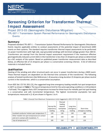
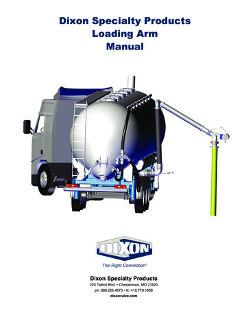
Thermal Design Considerations (cont.)TO CONTROLDESIGN PARAMETERAverageliquidtemperaturerise overambientCooling equipment —radiators or coolers,number / CFM rating offans, pumpsWinding currentAveragedensity, conductor size,winding tempnumber of radialrise overspacers, cooling ducts,ambientdirected flowWindinghottest spottemp riseover ambient.QrTtopQcT topTc,topradiatorsT varieslinearlyherecoilsQsQ c TbotQnQrTr,botTbottankAssumed oil temperature distribution inside tank. The oil flows, Q , aswell as the flow weighted temperatures are also indicated.Winding currentdensity, stray fluxTRANSFORMERS SERVICE TRAINING COMPONENTSTransformer Loading & Thermal Design Considerations – UTA TSDOS September 2013 SPX Transformer Solutions, Inc.8
Thermal Design Considerations (cont.)Three Principles of Heat Transfer1.ConvectionRequires contact between the heat source (the windingconductors which are heated by their losses, I2R stray andeddy currents) and the mineral oil, heating the oil.2.ConductionThe heated mineral oil transfers this oil to the radiatorswhere the oil will warm the radiator cooling fins by theconduction process.3.RadiationThe fins radiate heat to the ambient air, cooling thetransformer by cooling the oil.TRANSFORMERS SERVICE TRAINING COMPONENTSTransformer Loading & Thermal Design Considerations – UTA TSDOS September 2013 SPX Transformer Solutions, Inc.9
Thermal Design Considerations (cont.)Oil circulation removes heat from the windings.Transformer Loading & Thermal Design Considerations – UTA TSDOS September 2013TRANSFORMERS SERVICE TRAINING COMPONENTS SPX Transformer Solutions, Inc.10
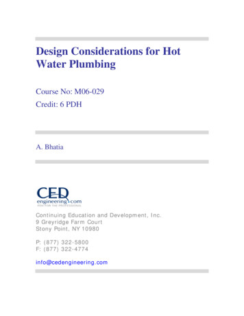
Thermal Design Considerations (cont.)Non-Directed Oil FlowOil is free tofind its ownpath from thebottom of thewinding tothe top ofthe winding.Directed Oil FlowWashers arestrategicallyplaced in thewinding todirect theoil flow.TRANSFORMERS SERVICE TRAINING COMPONENTSTransformer Loading & Thermal Design Considerations – UTA TSDOS September 2013 SPX Transformer Solutions, Inc.11
Thermal Design Considerations (cont.)Natural Circulation Natural circulation, orthermo-siphon, depends onthe density change of oilfrom temperature variationto produce oil flow Typical IEEE designationsinclude ONAN / ONAFTRANSFORMERS SERVICE TRAINING COMPONENTSTransformer Loading & Thermal Design Considerations – UTA TSDOS September 2013 SPX Transformer Solutions, Inc.12
Thermal Design Considerations (cont.)Forced Circulation Using pumps and ducting tocreate higher directed oil flowthrough the windings Higher cooling efficiency Typical IEEE designations OFAFOFWFODAFODWFTRANSFORMERS SERVICE TRAINING COMPONENTSTransformer Loading & Thermal Design Considerations – UTA TSDOS September 2013 SPX Transformer Solutions, Inc.13
Thermal Design Considerations (cont.) Radiators are most commonly used to increase the amount ofexposed oil surface area to the surrounding air in order toincrease the heat exchange rate efficiency If dictated by loading or space requirements, heat exchangersOFAF that employ pumps and fans, or OFWF (water coolers)can be used, at higher cost Fans are relatively inexpensive means to increase the rate ofheat dissipation from the radiators by increasing the volume ofair moving over the radiator surface Noise generated by the cooling fans varies with the bladedesign and speed of the cooling fans and often becomes alimiting factor in transformer loading and overall sizeTRANSFORMERS SERVICE TRAINING COMPONENTSTransformer Loading & Thermal Design Considerations – UTA TSDOS September 2013 SPX Transformer Solutions, Inc.14
Thermal Design Considerations (cont.)Oil Preservation SystemsSealed Tank Design Requires a gas space for expansion of the mineral oil Shipped from factory with nitrogen Designed for a max operating pressure of 8 psi with a125% safety factor(10 PSI) Supplied with a pressure /vacuum relief device asoverpressure protection IEEE minimum requirementTRANSFORMERS SERVICE TRAINING COMPONENTSTransformer Loading & Thermal Design Considerations – UTA TSDOS September 2013 SPX Transformer Solutions, Inc.15
Thermal Design Considerations (cont.)Oil Preservation Systems (cont.)Nitrogen Regulated Design Requires source of nitrogen Regulator system to maintainpositive pressure By customer specificationConservator Tank Design Separate oil reservoir (overflow) Requires desiccant breather and airbladder to ensure oil is not exposedto O2 and water By customer specificationTRANSFORMERS SERVICE TRAINING COMPONENTSTransformer Loading & Thermal Design Considerations – UTA TSDOS September 2013 SPX Transformer Solutions, Inc.16
Industry Practice on Transformer LoadingIndustry 1Power Transformer IEEE C57.91-2011 IEEE Guide forLoading Mineral-Oil-ImmersedTransformers andStep-Voltage RegulatorsC57.115-1991Power Transformer 100MVANOTE: IEC Publication 60076-7 is a 2005 update of IEC Pub 60354-1991TRANSFORMERS SERVICE TRAINING COMPONENTSTransformer Loading & Thermal Design Considerations – UTA TSDOS September 2013 SPX Transformer Solutions, Inc.17
Industry Practice on Transformer Loading (cont.)Theoretical Life 15000 27.604 Life exp HST 273Where, Life Life in hours at temperature HSTHST Hot Spot Temperature in CSource: C57.91-2011 IEEE Guide for Loading Mineral-Oil-Immersed Transformers and RegulatorsTRANSFORMERS SERVICE TRAINING COMPONENTSTransformer Loading & Thermal Design Considerations – UTA TSDOS September 2013 SPX Transformer Solutions, Inc.18
Industry Practice on Transformer Loading (cont.)a - Based on a normal life of 180,000 hrs (20.5 yrs). Time durations not shown are in excess of 24 h.b - This column of time durations for 0.0133% loss of life gives the hours of continuous operation above the basis-of-rating hottest-spot temperature(110 C) for one equivalent day of operation at 110 C.FAA – Aging Acceleration FactorSource: C57.91-2011 IEEE Guide for Loading Mineral-Oil-Immersed Transformers and RegulatorsTRANSFORMERS SERVICE TRAINING COMPONENTSTransformer Loading & Thermal Design Considerations – UTA TSDOS September 2013 SPX Transformer Solutions, Inc.19
Industry Practice on Transformer Loading (cont.)Basis50% retained degree of polymerization in insulation25% retained degree of polymerization in insulationDP 200 End of Life of InsulationInterpretation of distribution transformer functionallife test data (former IEEE Std C57.91-1981 criterion)Natural EsterMineral OilSealed Tube Test - ML 152-2000Upgraded Paper 500 hr @ 170 CNatural EsterMineral OilSealed Tube Test - ML 152-2000Upgraded Paper 1000 hr @ 170 CNormal Insulation .55180,000"Normal insulation life" of awell-dried, oxygen-free, 65 Caverage winding temperaturerise insulation system at thereference temperature ofNatural EsterMineral Oil Natural EsterMineral Oil110 C.Sealed Tube Test - ML 152-2000Upgraded Paper 2000 hr @ 170 C6 to 8 C reduction in hot-spot temperature doublestheoretical life.Transformer Loading & Thermal Design Considerations – UTA TSDOS September 2013Sealed Tube Test - ML 152-2000Upgraded Paper 4000 hr @ 170 CTRANSFORMERS SERVICE TRAINING COMPONENTS SPX Transformer Solutions, Inc.20
Industry Practice on Transformer Loading (cont.) Aging of insulation materials is dependent on more thanjust hot-spot temperature: Moisture Oxygen Temperature Time Proper application of oil preservationsystems and maintenance canminimize the moisture andoxygen content Proper loading practices canminimize the hot-spot temperatureReal WorldTransformer Loading & Thermal Design Considerations – UTA TSDOS September 2013TRANSFORMERS SERVICE TRAINING COMPONENTS SPX Transformer Solutions, Inc.21
Functional Life Defined as “conditions under which the transformer does notfunction as intended” Overloading impacts functional life: Bubbles in the oil can lead to dielectricfailures (hot-spot temp) Accelerated aging of gasket materials canlead to oil leaks Accelerated aging of insulation can lead todielectric or mechanical failures whenexposed to fault conditions Tank pressure build-up can cause gasketleaks and possible PRD operation (averageoil temp) Other loading related issues include current carrying componentsratings, CT saturation, lead heating and leakage flux overheatingTRANSFORMERS SERVICE TRAINING COMPONENTSTransformer Loading & Thermal Design Considerations – UTA TSDOS September 2013 SPX Transformer Solutions, Inc.22
Functional Life (cont.) Sourcesof bubbles: Gasses dissolved in oil Gasses generated fromdecomposition of insulation Water vapor from paper insulationin windings Suddenrelease of gas/vaporas bubbles is possible underoverloading conditions, dependingon dissolved gas levels and moisture contentof the insulationTRANSFORMERS SERVICE TRAINING COMPONENTSTransformer Loading & Thermal Design Considerations – UTA TSDOS September 2013 SPX Transformer Solutions, Inc.23
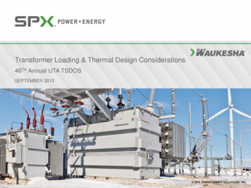
Functional Life (cont.)Temperature for bubbleformation is a function ofthe following: Moisture content ofinsulation % of dissolved gassesin oil Can occur at normaloperating temperaturesSource: IEEE T&D Conference in Atlanta in 2001 by T.V. OommenEPRI reports EL-6761, Marc
5.11.1.1 C of the IEEE Standard C57.12.00-2006. MVA Top Oil Bottom Oil HV Wdg LV Wdg TV Wdg. Guar Average Ambient Temp *Calc Hottest-Spot Winding Rise over Ambient Temp Radiator Qty Fan Qty Total Losses Kilo Watts 15 44.2 27.8 41.4 46.5 - 65 27.9 56.4 5 - 95.5 25 50.0 20.7 49.0 55.2 1-