Transcription
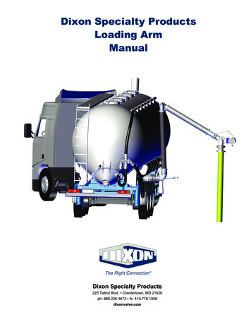
Dixon Specialty ProductsLoading ArmManualDixon Specialty Products225 Talbot Blvd. Chestertown, MD 21620ph: 888.226.4673 fx: 410.778.1958dixonvalve.com
IntroductionThis manual contains an order guide, installation and operating instructions, maintenance, trouble shooting and safety notes for theDixon Specialty Products Loading arm. Please read and understand this manual prior to installing, operating or servicing this product.Table of ContentsHow To Order Guide. 3 - 5Installation Instructions. 6Operating Instructions. 7 - 9Loading Arm Maintenance. 10 - 13Trouble Shooting. 14Safety . 14Limited Warranty. 152888.226.4673Loading Arm Manual
How To Order Guide1. Counterbalance part number sequence1Part NumberOrientationSpring ColorLoad eightContact Dixon for appropriate spring based on individual application.2. Common Accessories: (Many others available upon request such as: deadman style valves and ball-style handles.)D-handleBreakawayCam & grooveFlange extensionAPISplit-flange swivel locking devices (single hole location)Sight glassDeflectorsSplit-flange swivel locking devices (multiple hole locations)Note: Dixon offers a full engineering team to design and develop any product or new idea. We offer loading arms as either new turnkey systems or replacement parts for any loading arm application.Loading Arm Manual888.226.46733
How To Order Guide, cont.3. Right-handLea.Leg BgAHorizontal (top load)Leg BLeg Ad.Other style arm:4. Component Measurements and Material (measure from center of swivel to center of swivel to the whole foot, i.e. 48", 60", etc.)Leg ALength:Material:carbon steelaluminumstainless steelLeg BLength:Material:carbon steelaluminummetal hosestainless steelcomposite hose4888.226.4673Loading Arm Manual
How To Order Guide, cont.5. Application Informationa. End User:Distributor:Contact Name:Number:Email:Contact Name:Number:Email:b. Quantity:c.Pipe size:2"d. Base swivel:3"Type of media:Misc.Split flange stylee. Riser stand pipe connection:f.4"Asphalt"V-ring style150 ANSI flangeFuelO-ring style300 ANSI flangeTTMA flangeOther:Other mediag. Terminal end connections (optional items for each media):45 pipe cutbucket hookdeflectorhandleAPI couplerbreakawayflange extensionsight glassD handleball handlelocking mechanismh. Seals (Dixon can recommend based on media):Buna-NViton PTFEFKM A&BEPDM6. Site Limitations:a.Ceiling or roof height from riser pipe connection distance:b. Additional items (vapor hoses, drip buckets, hold-downchains etc. and estimated weight (pounds):c. Range of motion required (list approximate range of motiondesired by clock method or degree method):7. Sketches / Notes:Loading Arm Manual888.226.46735
Installation Instructions1. Wear Personal Protective Equipment (PPE). When performing maintenance or working on the Loading arm always wear adequatepersonal protection, including hard hats, gloves, safety glasses and steel-toed work boots.2. Lift using appropriately rated straps using the shown possible attachment points.3. Bolt torque chart and tighten sequence (use appropriate gaskets and bolts)4 Bolt8 Bolt12 Bolta. TTMA flange bolt(s) 25 Ft.Ibs. (tank truck flange)b. 150 Pound Flange bolt(s) 32 Ft.Ibs.c. Counterbalance clamp bolt(s) 30 Ft.Ibs.4. Prior to installing the loading arm on an existing riser pipe flange, inspection of the riser piping and connection flange should beconducted. Ensure that the inlet is leveled and plumb which will prevent the loading arm from rotational drift. Also, confirm theflange sealing surface is not damaged to prevent leaks.5. The entire loading arm should be assembled on the ground in a horizontal position and then raised to the inlet piping flange as acomplete overall unit. Most of our assemblies will be shipped completely assembled. Be sure to align all flange gaskets properly inbetween the flanges and tighten connections per the Bolt tightening sequence diagram.6. Once installed, adjust the spring tension per the spring adjustment section and position the upward/downward travel stop(s).Reference Operating Instructions on pages 7 - 9.6888.226.4673Loading Arm Manual
Operating InstructionsItemQtyPart NumberDescription13AT1321Button head stainless steel Allen screw - metric 421AT1299Stainless steel name plate31AT1320Stainless steel grease fitting41AT1264Carbon steel side mounting52AT1302Socket head stainless steel Allen screw - 5/16" x 1½"61AT1301Stainless steel travel stop71AT1325Brass bushing81AT1326Ductile iron actuator91AT1255Carbon steel main body103AT1318Stainless steel hexagonal head bolt ⅝"-11 x 1½"113AT1319Stainless steel grower washer ⅝"121AT1324Torsion spring131AT1258Stainless steel cylindrical washer141AT1262Adjustment bolt151AT1327Brass washer ⅝"1684AT1328Ball bearings ⅜"171AT1256Carbon steel female raceways body181AT1257Carbon steel male raceways adjusting device192AT1296Stainless steel grease fitting cups201AT1329Environmental seal211AT1300Stainless steel plate223AT1321Button head stainless steel Allen screw - metric 4Loading Arm Manual888.226.46737
Operating Instructions, cont.Counterbalance adjustment and balancing. The loading arm is balanced and adjusted at the factory for all complete arm packagesbut may need minor fine tuning once installed on-site due to weight of media, shipping vibrations etc.1. Spring adjustment:a. Prior to any work, reference the Safety section on page 14. Wear Personal Protective Equipment (PPE) during the installation. Remove Dixon cover on the side with the pivot arm (item 2). Remove the mechanical stop secured with two hex bolts (items 5 and 6). Remove tension from the spring by lifting the arm up. Lift the loading arm to highest possible position to unload springtension and secure the arm. Once tension is removed, make small ½ turn increments to the adjustment bolt (item 14). Use caution when releasing thearm. Allow the arm to 'settle' into a natural position before determining whether or not further adjustment is required.- Tightening increases spring torque/loosening decreases spring torque.8888.226.4673Loading Arm Manual
Operating Instructions, cont.2. Spring wear (removal and replacement)a. As the spring is used over time, the spring wears until the spring has reached the end of it’s service life: To change the spring out, all tension must be removed from the spring and the pivot arm bar must be removed. Remove 3 bolts on the pivot arm side of the counterbalance (Item 10).Pull the carbon steel side mount end plate (item 4) and associated parts of the housing.Remove the spring (item 12) and replace.Reinstall in the reverse order.3. Effects of pipe clamp movement:a. As the clamp is moved further out on the arm the result will be less felt weight at the terminal end and if the clamp is movedcloser to the pivot location the more felt weight will result.b. Clamp bolts should be tightened in a crisscross pattern to 30 ft lbs. and checked during a regular maintenance schedule.Loading Arm Manual888.226.46739
Loading Arm MaintenanceReference the following information to assist in general maintenance and seal replacement for all Dixon Specialty Products swiveljoints. Take all necessary safety precautions when assembling and operating these units. Handle all components with cleanliness andcare.1. Lubrication (grease fittings)a. Grease schedule: Lubrication should be performed on a regularly scheduled basis (e.g. bi-annually, quarterly or monthly),depending on service and operating conditions.b. Inject grease and rotate the unit as it is applied to ensure an even application throughout the raceway. Do not over-lubricate,as this may displace the seals and result in leakage. Use a manual grease gun in order to feel pressure inside the swivel,if you feel the pressure is high the swivel may be over greased and one of the ball plugs should be removed for a visualinspection. Periodically remove both ball plugs in order to visually inspect the ball race and one or two of the ball bearings.If there is material inside this cavity the pressure seal has been compromised resulting in a leak and the swivel should berebuilt. If you find metal in the grease or have any concerns about the shape of the ball bearings or races please contact usimmediately as this could be signs of excessive wear.c. Grease points: all swivel joints are supplied with a grease fitting at each plane of rotation. Special note about the split flangestyle swivel: remove the "grease inspection port" prior to greasing(see page 13).d. Type of grease: all swivels are filled with Renolit Replex 2 grease at the factory with NLGI Grade 2. Some applications mayrequire different grease available upon request.2. Re-torque bolts (clamps, counterbalance bolts, flanges etc.) and ensure the E-clips are in place on the counterbalance pivot bar(e.g. bi-annually, quarterly or monthly), depending on service and operating conditions. We recommend using a thread lock sealantor lock washers to prevent any loosening due to vibration (Loctite Blue).3. We recommend a spring adjustment on the counterbalance after the first 2 months in service depending on use to account forinitial spring wear. (see spring adjustment section in this manual)4. All swivels are designed to be rebuildable once they have reached the end of their service life, refer to pages 11 - 13 for swivel sealreplacement procedures.10888.226.4673Loading Arm Manual
Loading Arm Maintenance, cont.Swivel work instructions for replacing O-ring swivel seals.Note: Instructions are not for assembly with spring-loaded PTFE pressure seal, consult Dixon .1Remove the ball retainer screws. Add a sufficient amount ofsolvent into each raceway to flush out the lubricant. Rotatethe sleeve, catching the balls as they fall out. When all the ballshave been removed, the body and sleeve can be separated.Discard old seals. Thoroughly clean the body and sleeve.23Install the new O-rings on the sleeve, dust seal to the rear,product (pressure) seal up front.Lubricate the body and the sleeve with grease.4Insert the sleeve into the body, slowly rotate the sleeve whileinserting into the body.5When the sleeve is fully inserted, feed the ball bearings intothe raceways while rotating the sleeve. To make space for allthe balls, insert a screw driver into the raceway, while continuingto rotate the sleeve in one direction (be careful not to damagethe threads). This will cause the balls to jam up, making room forthe remaining balls. Now reverse rotation of sleeve and insert theremaining balls.6Reinstall ball retainer screws until tight. If thisinterferes with the smooth rotation of the ball bearings, thenback off 1/8 - 1/4 turn. A thread locking sealant is recommendedto prevent screws from backing off. After pressure testing, theunit is ready for installation.Body and sleeve are matched during manufacturing. Do not mix components with other units.Loading Arm Manual888.226.467311
Loading Arm Maintenance, cont.Swivel work instructions for replacing V-ring swivel seals.1Remove the ball retainer screws. Add a sufficient amount ofsolvent into each raceway to flush out the lubricant. Rotatethe sleeve, catching the balls as they fall out. When all the ballshave been removed, the body and sleeve can be separated.Discard old seals. Thoroughly clean the body, sleeve retainer,spring retainer and springs. 124Set the dust seal into O-ring groove on the sleeve. Place theseal retainer on the sleeve with the grooved end facing theV- rings. Lubricate the sleeve with grease.5Lubricate the body unit with a moly lubricant or equivalent.Insert sleeve into body, compressing swivel joint together untilball races of body and sleeve are in alignment (do not rotateeither unit while compressing). Care should be taken to avoidpinching or scoring of V rings. Drop balls into raceway holes,rotating the sleeve slowly as you load. To make space for all theballs, insert a screw driver into the raceway while continuing torotate the sleeve in one direction (be careful not to damage thethreads). This will cause the balls to jam up, making room for theremaining balls. Now reverse the rotation of the sleeve and insertthe remaining balls.3Place the assembled spring retainer unit (spring end first) intothe body. Place the set of V-rings onto the spring retainer. Besure V-rings are installed with the sealing lips facing toward theretainer. Lubricate the body and seals with a Moly lubricant orequivalent.6Reinstall ball retainer screws until tight. If this interferes withthe smooth rotation of the ball bearings, then b
We offer loading arms as either new turn-key systems or replacement parts for any loading arm application. Split-flange swivel locking devices (single hole location) Split-flange swivel locking devices (multiple hole locations) 1 Contact Dixon for appropriate spring based on individual application. 4 888.226.4673 Loading Arm Manual How To Order Guide, cont. 3. Configuration(s) 4. Component .

