Transcription
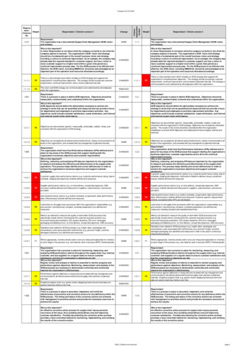
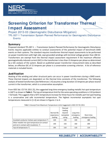
Screening Criterion for Transformer ThermalImpact AssessmentProject 2013-03 (Geomagnetic Disturbance Mitigation)TPL-007-1 Transmission System Planned Performance for Geomagnetic DisturbanceEventsSummaryProposed standard TPL-007-1 – Transmission System Planned Performance for Geomagnetic DisturbanceEvents requires applicable entities to conduct assessments of the potential impact of benchmark GMDevents on their systems. The standard requires transformer thermal impact assessments to be performedon power transformers with high side, wye-grounded windings with terminal voltage greater than 200 kV.Transformers are exempt from the thermal impact assessment requirement if the maximum effectivegeomagnetically-induced current (GIC) in the transformer is less than 15 Amperes per phase as determinedby a GIC analysis of the system. Based on published power transformer measurement data as describedbelow, an effective GIC of 15 Amperes per phase is a conservative screening criterion. A list of referencematerials is included herein.JustificationHeating of the winding and other structural parts can occur in power transformers during a GMD event.These thermal impacts are dependent on the thermal time constants of the transformer. The followinganalysis of tested transformers [See References 1-4] assumes a long-duration 15 Amperes per phase neutralcurrent in the transformer, which is a conservative assumption.From IEEE Std. C57.91 2011 [5], the suggested long-time emergency loading metallic hot spot temperatureis 160 C as shown in Table 1. The top oil temperature limit for the same operating conditions is 110 (ambient full load). This suggests that a 50 C temperature increase for three hours for metallic part hot spot heatingis a conservative and safe incremental temperature. The highest incremental asymptotic hot spottemperatures measured in [1-4] are shown in Figures 1 to 4.TABLE 1:Excerpt from Maximum Temperature Limits Suggested in IEEE C57-91 2011Insulated conductor hottest-spot temperature COther metallic hot-spot temperature (in contactand not in contact with insulation), CTop-oil temperature CNormal emergency loading180140150160200105110110110
Figure 1 corresponds to the thermal asymptotic response of the tie plate of a 500/16.5 kV 400 MVA singlephase Static Var Compensator (SVC) coupling transformer [1]. The asymptotic behavior for GIC values above5 Amperes per phase has been linearly extrapolated. Although such extrapolation is probably veryconservative for GIC values above 40 Amperes per phase it is consistent with the thermal behavior ofmetallic hot spots demonstrated in other measurements (e.g., [2], [3]). The incremental asymptotictemperature for 15 Amperes per phase is 46.8 GIC A/phaseFigure 1: Asymptotic thermal response of the tie plate of a 500 kV 400 MVA single-phase SVC couplingtransformer.
Figure 2 corresponds to the thermal asymptotic response of tie plate of a 735 kV 370 MVA single-phasecore-type autotransformer [2]. The asymptotic response depicted in Figure 2 is a combination ofmeasurements and calculated values. In this case, 12.5 Amperes per phase caused an increase of 36 Cwhile 25 Amperes per phase caused an increase of 89 C. Interpolation between these two points gives anincrease of 47 C at 15 Amperes per phase. The highest current injected into this transformer is reportedas 75 Amperes per phase for 1 hour. The transformer was energized from the 735 kV terminals and weaksource uncertainties normally seen in factory floor tests [4] would have been low in these 530GIC A/phaseFigure 2: Asymptotic thermal response of the tie plate of a 735 kV 370 MVA single-phase core-typeautotransformer.Screening Criterion for Transformer Thermal Impact Assessment: Project 2013-03 (Geomagnetic Disturbance Mitigation) June 12, 2014 3
Figure 3 corresponds to the thermal asymptotic response of the top and bottom clamps of a 400 kV 400MVA five-leg core-type fully-wound transformer [3]. Hot spot temperature of 34 C for 15 Amperes perphase occurred at the Flitch plate. Highest current injected into this transformer is reported as 66.67Amperes per phase for approximately 10 minutes. The transformer was energized from the 400 kVterminals and weak-source uncertainties would have been IC A/phasech14ch7ch18Figure 3: Asymptotic thermal responses of the bottom and top yoke clamps (ch14 and ch7), and Flitchplate (ch18) of a 400 kV 400 MVA five-leg core-type fully-wound transformer.Screening Criterion for Transformer Thermal Impact Assessment: Project 2013-03 (Geomagnetic Disturbance Mitigation) June 12, 2014 4
Figure 4 shows tests carried out in a factory floor of a fully instrumented 400 kV 400 MVA single-phasecore-type autotransformer. Tie-plate hot spot temperature of 46 C for 15 Amperes per phase wasmeasured. The weak ac supply is an issue in these tests and the actual asymptotic response for lowervalues of GIC above 10 A/phase is probably higher than measured. However at these relatively low GICvalues, saturation of structural parts is not a dominant issue.SoCo100Incremental temperature9080706050403020100051015202530GIC A/phaseMeasured warmFigure 4: Asymptotic thermal responses of the tie plate of a 400 kV 400 MVA single-phase core-typeautotransformer.In all of the test results presented, an effective GIC value of 15 Amperes per phase resulted in a temperatureincrease of less than 50 C. These results strongly support use of 15 Amperes per phase as a conservativecriterion for determining which applicable transformers require assessment using more detailed methodslike those described in the Transformer Thermal Impact Assessment white paper [6]. Furthermore there issignificant margin in the assumption of an injected dc current of 15 Amperes per phase for three hours (asopposed to GIC time series information). This conservative approach provides ample margin to account forany uncertainty resulting from the limited number of tested transformers.Screening Criterion for Transformer Thermal Impact Assessment: Project 2013-03 (Geomagnetic Disturbance Mitigation) June 12, 2014 5
References[1] Marti, L., Rezaei-Zare, A., Narang, A. , "Simulation of Transformer Hotspot Heating due toGeomagnetically Induced Currents," IEEE Transactions on Power Delivery, , vol.28, no.1, pp.320-327,Jan. 2013[2] Picher, R.; Bolduc, L.; Pham, V.Q., "Study of the Acceptable DC Current Limit in Core-Form PowerTransformer," Power Engineering Review, IEEE , vol.17, no.1, pp.50,51, January 1997[3] Lahtinen, Matti. Jarmo Elovaara. “GIC occurrences and GIC test for 400 kV system transformer”. IEEETransactions on Power Delivery, Vol. 17, No. 2. April 2002.[4] NERC GMD TF Presentation, Atlanta, Nov.2013 mer%20Session.pdf?Mobile 1&Source %2Fcomm%2Fpc%2F [5] "IEEE Guide for loading mineral-oil-immersed transformers and step-voltage regulators." IEEE StdC57.91-2011 (Revision of IEEE Std C57.91-1995).[6] Transformer Thermal Impact Assessment white paper. Developed by the Project 2013-03(Geomagnetic Disturbance) standard drafting team. Available ng Criterion for Transformer Thermal Impact Assessment: Project 2013-03 (Geomagnetic Disturbance Mitigation) June 12, 2014 6
From IEEE Std. C57.91 2011 [5], the suggested long-time emergency loading metallic hot spot temperature is 160 C as shown in Table 1. The top oil temperature limit for the same operating conditions is 110 (ambient full load). This suggests that a 50 C te mperature increase for three hours for metallic part hot spot heating is a conservative and safe incremental temperature. The highest .