Transcription
Challenge: Mobile Optical Networks Through VisualMIMOAshwin Ashok, Marco Gruteser, Narayan MandayamWINLAB, Rutgers University, 671 Route 1 South, North Brunswick, NJ, USAaashok@rutgers.edu, {gruteser, narayan}@winlab.rutgers.eduJayant Silva, Michael Varga, Kristin DanaDepartment of ECE, Rutgers University, 94 Brett Road, Piscataway, NJ, USA{jayantms, mfvarga}@rutgers.edu, kdana@ece.rutgers.eduABSTRACTCategories and Subject DescriptorsMobile optical communications has so far largely beenlimited to short ranges of about ten meters, since thehighly directional nature of optical transmissions wouldrequire costly mechanical steering mechanisms. Advances in CCD and CMOS imaging technology alongwith the advent of visible and infrared (IR) light sourcessuch as (light emitting diode) LED arrays presents anexciting and challenging concept which we call as visualMIMO (multiple-input multiple-output) where opticaltransmissions by multiple transmitter elements are received by an array of photodiode elements (e.g. pixels in a camera). Visual-MIMO opens a new vista ofresearch challenges in PHY, MAC and Network layerresearch and this paper brings together the networking, communications and computer vision fields to discuss the feasibility of this as well as the underlying opportunities and challenges. Example applications rangefrom household/factory robotic to tactical to vehicularnetworks as well pervasive computing, where RF communications can be interference-limited and prone toeavesdropping and security lapses while the less observable nature of highly directional optical transmissionscan be beneficial. The impact of the characteristics ofsuch technologies on the medium access and networklayers has so far received little consideration. Examplecharacteristics are a strong reliance on computer visionalgorithms for tracking, a form of interference cancellation that allows successfully receiving packets frommultiple transmitters simultaneously, and the absenceof fast fading but a high susceptibility to outages due toline-of-sight interruptions. These characteristics lead tosignificant challenges and opportunities for mobile networking research.C.2.1 [Computer-Communication Networks]: Network Architecture and Design—Wireless CommunicationPermission to make digital or hard copies of all or part of this work forpersonal or classroom use is granted without fee provided that copies arenot made or distributed for profit or commercial advantage and that copiesbear this notice and the full citation on the first page. To copy otherwise, torepublish, to post on servers or to redistribute to lists, requires prior specificpermission and/or a fee.MobiCom’10, September 20–24, 2010, Chicago, Illinois, USA.Copyright 2010 ACM 978-1-4503-0181-7/10/09 . 10.00.General TermsDesign, Measurement, Experimentation, PerformanceKeywordsVisual MIMO, Optical Communication, Computer Vision, RF Communication, Line of Sight(LOS)1.INTRODUCTIONRadio frequency based wireless communications andnetworking has seen tremendous growth over the lastseveral years serving as the foundation for myriad applications. With such increased adoption, the non-line ofsight and ubiquitous propagation characteristics of wireless communications at typical radio frequencies, whileoften an advantage, are also leading to many unmitigated challenges. For example, they lead to increasedco-channel interference, eavesdropping, and spoofing risksthat make it hard to meet stringent reliability or security requirements. For many applications ranging fromhousehold and factory robotics to vehicular networksto pervasive computing, wireless communication in theoptical spectrum can address such challenges throughdirectional transmissions with narrow beamwidths andline-of-sight restrictions. These directional transmissions reduce co-channel interference through improvedspatial reuse and make it difficult for an eavesdropperto detect the presence of communications. In contrast,achieving similar beamwidths in the RF spectrum is impractical as it would require inordinately large antennas,due to the larger wavelength.Advances in CMOS imaging technology along withthe advent of visible and infrared (IR) light sources suchas light emitting diode (LED) arrays or LCD screenspresent an exciting and challenging concept to enablemobile optical networking. In this concept, which wecall as Visual-MIMO (visual multiple-input multipleoutput), optical transmissions by multiple transmitterelements are received by an array of photodiode ele-
ments (e.g. pixels in a CMOS camera). This paperbrings together the networking, communications andcomputer vision fields to discuss the feasibility of thisconcept as well as the underlying opportunities and challenges in PHY, MAC, and Network layer research.Mobile Optical Limitations. Optical wireless communications with narrow beams, however, has hithertobeen impractical in most mobile settings, because boththe sender and receiver need to operate with very narrowbeams and angles-of-view, respectively, to achieve transmission ranges greater than a few tens of meters. Except for short-range diffuse IR transmitters with a rangeof about 10m [1, 18] wireless optical transmissions arethus largely confined to stationary building-to-buildingtransmission links. Free-space optics transceivers designed for this purposes can achieve ranges of a fewkilometers under good weather conditions [15]. Due tothe extremely narrow beamwidths used, any application with some mobility would require costly mechanicalsteering systems for transmitter and receiver [11].Optical wireless requires very narrow beams to achievelonger ranges because the signal-to-noise ratio is limited by several factors. First, transmission power levelsare lower than in the RF spectrum because of outputpower limitations of LED technology and eye safety restrictions for laser transmitters. The optical spectrumis characterized by high background noise typically bysunlight in the infrared and visible light wavelengthsand other IR heat sources in vicinity. The radiation ofvisible light emitted by the sun is many orders of magnitude higher than the power it emits in radio frequencies.Third, in addition to this background noise, optical receivers experience shot noise. Shot noise is caused bythe random arrival of photons at the receiver. Since theenergy of one photon in the optical spectrum is muchhigher than in the radio spectrum, fewer photons willbe generated at the same transmission power level andat these lower quantities variations from random arrivalpatterns have a more significant effect on signals. Thus,in optical systems shot noise dominates thermal noise,which is a main receiver noise source in RF systems.The Visual MIMO Approach. This paper argues that it is now becoming feasible to overcome thetransmission range limitations of conventional wirelessoptics through camera receivers and LED transmitterarrays and that developing protocols and mobile computing systems with this technology presents many exciting new research challenges for the mobile networking and computing community. The image sensor in acamera is essentially an array of photodiodes and thecamera lens provides a different narrow field of view foreach photodiode. This creates a large number of highlydirectional receive elements (the camera pixels), whichallows reducing interference and noise and thereby canachieve large ranges, yet still maintain the wide field-ofview necessary for mobile communications. The tradeoffs in the visual MIMO system, however, are a limitedreceiver sampling frequency (e.g., hundreds to thousandframes per second for lower end cameras and a million frames per second for high-end models) and, asin all optical wireless communications, strong line-of-sight (LOS) requirements. To address the rather limited frame rate (sampling frequency) of current cameras, the system can use a visual MIMO approach, i.e.transmit with multiple LEDs and record the signal withmultiple camera pixels. As we will discuss, this approach can also allow many “parallel” communicationchannels, similar in concept to RF MIMO systems [13],albeit over a channel with very different characteristics.At the physical layer, the visual MIMO approach requires techniques to acquire and track signals from atransmitter as they are captured by different photodiodes (pixel) during movement. We show how a physical layer could rely on computer vision/image analysisas opposed to traditional baseband signal processing,opening many avenues for interdisciplinary research. Atthe PHY layer, visual MIMO can also benefit from exploiting the multiplexing/diversity tradeoff as a function of the resolvability of multiple images on the imageplane at various distances between the transmitter andreceiver. This differs from the channel fading dependent multiplexing/diversity gain tradeoffs in RF-MIMOsystems where distance is not a key concern. At theMAC layer, visual MIMO can also benefit from novelchannel access mechanisms that adapt between paralleltransmissions when “interference cancellation” is possible and separate channel access when it is not. Thereliance on line-of-sight communications and the factthat mobility (e.g. such as in vehicular or robotic networks) may present intermittent links, as well as theperspective-dependent achievable throughput also callsfor new visions for MAC and networking layer protocolsthat can keep track of network geometry.Applications. Several key applications in the mobile computing field could benefit from visual MIMO.First, safety applications in vehicular networks such asemergency electronic brake lights (EEBL) [37] and cooperative collision warning (CCW) [10] require reliablecommunications under potentially high co-channel interference because vehicle position and dynamics information needs to be shared among nearby vehicles in potentially very dense highway scenarios. Visual MIMOcould reduce interference because it’s directional andline-of-sight transmissions allow for increased spatial reuse.Communications in military applications can be enhanced by the increased security of visual MIMO channels. The line-of-sight requirement greatly reduces thepotential for interception and jamming that is inherentin RF communication. Additionally, the source of thesignal interception can be more easily determined, so thepotential for spoofing signals is reduced. Longer rangecommunication could be accomplished by a network ofvisual MIMO channels consisting of cameras/monitorrelay stations.The ubiquitous placement of LCD screens and surveillance cameras in urban environments create numerousopportunities for practical applications of visual MIMOchannels. LCD screens for electronic signage can havedual functionality by transmitting embedded signals viaintensity modulation, so that visual observation for human observers would coexist with a visual MIMO wireless communications channel. Alternatives to intensity
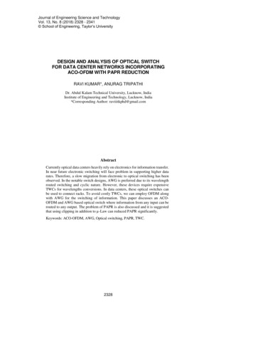
modulation include the use of angle-based modulationwhere observation of the screen at different angles enables different visual observation. Angle-based modulation can be accomplished via polarization methodsor digital mirror arrays. Such embedded signals mayalso enable new user interface, for example by facilitating recognition of pointing or gestures with a cameraequipped mobile device.Visual MIMO also may find application in computervision, where camera networks refer to the cooperationof numerous cameras viewing a scene in order to create a3D environment map. The key challenges in these networks is (1) accurate camera calibration so that eachcamera has a known position/orientation and (2) accurate point correspondences in order to compute geometry via stereo or structure-from-motion algorithms.Camera networks can utilize visual MIMO protocols totransmit/receive a temporal pattern to uniquely identify key scene points to provide unambiguous point correspondences and enable robust camera calibration evenin low light conditions. An interesting merger of computer vision recognition algorithms with communications protocols can be explored by recognizing not staticpassive objects, but objects that are communicatingknown temporal pilot sequences and headers.To focus our discussion, the remainder of this paperwill discuss the visual MIMO concept in the context ofvehicular network communications.2.RELATEDWhile there is a large body of work in optical networking [25] and free space optics [24, 5], it largely focuses on stationary rather than mobile networks. Except for recent spherical FSO transceiver designs for mobile ad hoc networks [36] and optical satellite communications with physical steering [11, 28], mobile opticalcommunications research has primarily focused on shortrange infrared communications for mobile devices [18,33]. While earlier work has used cameras to assist insteering of FSO transceivers [35],the visual MIMO approach differs by directly using cameras as receiver todesign an adaptive visual MIMO system that uses multiplexing at short distances but still can achieve ranges ofhundreds of meters in a diversity mode. It exploits advances in CMOS imagers that allow higher frame ratescompared to earlier CCD designs.IR has a small range (typically up-to 10m), the effective power of the IR beam has to be restricted tonot damage human tissues, and IR transmitters are relatively costly to build. Thus, more recently, researchhas also explored using the visible light spectrum forcommunication [20, 30, 3, 27, 19]. Low-speed audiocommunication systems using LED transmitters havealready been demonstrated [29]. In Japan, a consortiumof 21 research groups called the Visible Light Communication Consortium (VLCC) has been formed to research into areas of VLC [3]. Since 2008, the SmartLighting research group at Boston University [2] hasbeen investigating visible light communication systemsfor indoor lighting and outdoor vehicle to vehicle applications [9]. All this work generally uses photodiodesat the receiver to convert the optical signals to electrical signals. Though photo diodes can convert pulses atvery high rates, they suffer from large interference andbackground light noise. This results in very low signalto-noise ratios (SNR), which leads to the short rangeof typical IR communication systems, even with moresophisticated receiver processing and modulation techniques as studied in [32].Only a few sporadic projects have recently begun toinvestigate cameras as receivers, particularly for intervehicle communications [34] and traffic light to vehiclecommunications [8]. Their analytical results show thatcommunication distances of about 100 m with a BER 10 6 are possible. Other work has investigated channel modeling [20] and multiplexing [4]. More recently,researchers of the MIT Bokode project [23] have appliedcomputational photography to camera based communications. Building on such results and directions, thispaper argues that the novel concept of visual MIMOis becoming feasible and that it presents exciting opportunities and challenges to the mobile computing andnetworking community.3.LED-CAMERA COMMUNICATIONSPhotodiode arrays of a camera can provide a widereceiver field of view that allows for node mobility without the need to realign the receiver. Yet, by virtue ofthe camera design, each single photodiode element hasa very narrow field of view, allowing high gain communication. The camera lens creates the effect of each photodiode being angled to a slightly different part of thescene, so that the combination of all diodes generates animage with a wide field of view. Other research groupshave recently proposed variations of such designs [33].For example, if larger receiver sizes are practical, thelens can be eliminated by using a photodiode array ona spherical receiver structure [26].3.1Capacity AnalysisFigure 1: LED-Photodiode/Camera Communication IllustrationWe analyze a stationary communication model wherea single LED with output power Pt transmits to an optical receiver over a wireless channel as shown in figure 1.This is a conservative model, because it does not includethe effect of scene noise due to motion and achievablegains from multiple parallel transmission (from multipleLEDs). The two types of optical receivers we consider inour analysis are, (a) a conventional photodiode receiverand (b) a photodiode array (camera) receiver.
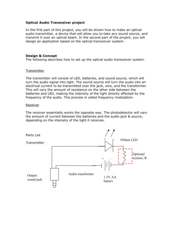
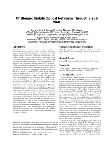
In an optical wireless channel, since the frequency ofthe optical signal is very large compared to the rateof change of the impulse response, multipath fadingand doppler shift are negligible. As described by Kahnand Barry [18], the received signal power follows Pr (RhPt )2 where h is a channel parameter called channel DC gain and R is the receiver’s responsitivity orthe optical power to current conversion ratio. Howeverthe received signal is corrupted by noise from the optical channel which is typically dominated by shot noisefrom background light sources and modeled as an additive white Gaussian process (AWGN) with a two sidedpower spectral density per unit area S(f ) qRPn [34,18]. Here, q is the electron charge and Pn quantifiesthe power in background light per unit area. Hence,for a receiver sampling rate of W , the noise power isPN qRPn AW where A is the area of the photodiode. The signal to noise ratio for a single LED-singlephotodiode communication is,SN Rpd κPt2 d 4Pr PNqRPn AW(1)where κ is a function of parameters such as the LED’slambertian radiation pattern, irradiance angle, field-ofview and optical concentration gain of the receiver [18].Applying the model to the photodiode array receiver,we observe that the key difference between a conventional photodiode receiver and an array receiver lies inthe detector area. When using the array, we assumethe receiver can select the subset of diodes that actuallyobserve a strong signal from the transmitter. This effectively reduces the detector area size and consequentlyreduces the noise. For the camera receiver (with a fixedfocus setting of the camera lens), we estimate the areaof the array actually used through perspective projection [17]. Given a focal length f , a round LED of diameter l and the distance d between camera and LED,the LED will occupy a circle of diameter l0 fdl onthe photodetector array. To conservatively account forthe quantization effects, we assume that it will occupya square area of size l02 . This noise reduction gain is,however, limited by camera resolution. When the LEDmoves away from the camera, the projected diameter l0will eventually become smaller than the size of a photodiode. From this point on, the camera cannot furtherreduce the number of photodiodes that are used in thereception process and its performance becomes similarto a single conventional photodetector (having the sizeof one pixel). We refer to distance where the LED generates an image that falls onto exactly one pixel as thecritical distance dc f l/s, where s is the edge-lengthof a pixel.Following this analysis, the signal to noise ratio fora single LED-photodiode array(camera) communicationis, κPt2 d 2if d dc2 2nW f l(2)SN Rcam qRP2 4 κPt d 2if d dcqRPn W sWe observe from equations (1) and (2), for d dc ,that a camera receiver has gain in SNR over a single pho-todiode receiver in the order of d2 . Thus at larger distances a camera would be a more resourceful option thana single photodiode receiver. Also for d dc , thoughthe camera receiver is equivalent to a single photodiodethe gain in performance can be achieved by reducingthe pixel size s which is not possible in a photodetector.Since current off-the-shelf camera implementations aremore limited in sampling rate (which equates to framerate in camera) than photodetectors, a camera systemwill likely achieve even higher SNRs than a photodetector with a high-sampling rate. The lower framerate,however, also directly limits achievable rates.To understand this tradeoff, given that the noise modelis AWGN, we plot the Shannon capacity C W log2 (1 SN R) over a range of distances in figure 2 for a single photodiode receiver and three different camera receivers. We set the sampling rate at 100MHz for thephotodiode and 1000fps for the Basler Pilot piA640 machine vision camera & 100fps for SONY PS3eye webcam (two off-the-shelf cameras which use a CCD imagesensor). We also consider a hypothetical camera whichcould sample at a rate of 1M fps. The parameter valuesunderlying this result are summarized in Table 1. Thegraph shows that even at the low sampling rates of atoy webcam the camera system can still outperform thesingle photodiode due to its SNR advantage at largerdistances. Moreover, the capacity of the camera systemcan be increased considerably by using an array of LEDtransmitters (appropriately spaced) where the capacityat short distances can be scaled by a number equal to thenumber of LEDs and in some cases at longer distancestoo. We also see that the capacity of a camera systemis more consistent over distance than for a single photodiode system for which it falls off rapidly (relatively)over distance.Figure 2: Capacity versus distance for the proposed system with Photodiode and Camera receiversTo further illustrate the camera advantage of eliminating noise by selecting only the photodiodes that receive the signal, we conduct an experiment with a blinking LED positioned 2m from the camera. The camerarecords a sequence of images in this completely stationary scenario. Figure 3 shows two histograms of the meanpixel value, one computed over a 10 10 area centered onthe LED and one computed over the complete 640 480image. These represent a single photodiode approach
and a camera with the ability to eliminate backgroundnoise as discussed. The figure shows that in the firstcase the on and off state can be clearly distinguishedthrough pixel values while in the second case the distinction is difficult since the signal is masked by shotnoise.Figure 3:Histogram plots of Basler Pilot piA640 camera snapshots in mediumsunlight(left:10 10, right:640 480)Note that in a mobile transmitter-receiver scenariothe camera’s SNR gain (and hence the capacity gain)over a single photodiode can be expected to be pronounced because of scene noise, for example in a situation where the ‘scene’ has a strong reflector such as awhite body. By extracting only those areas of the imagethat observe a strong transmitter signal, a camera canalso selectively eliminate these distractors (noise) whichis not possible with a single photodiode.ParameterPt [mW]F OV ψ[deg]A[mm2 ]Pn [mW/cm2 ]l[mm]f 1005015.760066.56Table 1: Table of parameter values for photodiode and camera(PD Photodiode,B Basler PilotpiA640, S SONY PS3eye)4.TOWARDS A VISUAL MIMO PHY- ACOMPUTER VISION APPROACHTo realize the potential capacity gains described inthe previous section, the visual MIMO system needs toidentify which set of photodiodes receive the signal, orequivalently, which region of the image contains LEDtransmitters. The output of the photodiode array inthis case is equivalent to an image, where each pixel isanalogous to a single photodiode. This task of identifying which region in the image contains LED transmittersis analogous to antenna selection in RF MIMO systems.Conventional techniques such as known pilot sequencesare not suitable for the visual MIMO system because ofthe framerate limitations of cameras. High frameratesare usually achieved by reading data only from one ormore small regions of interests (a limited set of photodiodes). When the set of photodiodes that receive thesignal is not yet known the complete array of photodiodes must be read out, which is only possible at lowerframe rates. Due to node mobility and a lower framerate, the set of photodiodes receiving the signal canchange before the pilot sequence is completed, rendering the pilot sequence approach ineffective.We propose to draw from techniques in the computer vision community to develop receiver-side processing techniques that can identifying and tracking the pixels that contain the image. Visual imagery is rich in detail and objects in images can be represented computationally via feature vectors. Given a computational representation for LED transmitters, feature-based recognition can be used for localization, or signal acquisition,even with the complexity of dynamic traffic scenes.Challenges of Real World Scenes. The challenges presented include: (1) camera motion , (2) illumination variation and (3) background distractors such asother vehicles on the road. Camera motion is inherentlypresent in the visual MIMO communications system because the camera at the receiver and LED transmittersare on different mobile nodes. Consequently, the geometry of the image formation process varies, i.e. theposition and orientation of the camera center with respect to the scene varies. As the camera moves further, the object of interest appears to become smaller.Because of this perspective projection, the LED transmitter undergoes arbitrary scaling, and the standardcommunications approach of template matching withmatched filters or with correlation-based detectors is insufficient. The computer vision literature has numerousmethods for achieving scale invariance in object recognition. In our prototype system we employ the popularapproach of SIFT-matching [21], scale invariant featuretransform, for representing and recognizing the LEDtransmitter.While camera motion creates geometric issues in matching, illumination variation causes photometric issues toovercome for LED transmitter localization. The appearance of the LED transmitter changes with illuminationvariation in the scene. Therefore, simple intuitive methods (such as detecting the red region) do not work inpractice. The problem of color constancy is well documented in the computer vision literature [16, 12, 6].While human perception creates a constant color representation of objects, the color measurement varies dramatically and is not a reliable method for detection.In this system, the feature-based representation for theLED transmitter is robust to photometric variations dueto illumination changes (e.g. sun vs. shade) as well asgeometric variations due to camera motion.The use of CV algorithms also helps to locate theLED transmitter in the presence of background distractors. Recall that the primary advantage of the visualMIMO channel over standard communication channelsis the ability to focus attention at the correct portionof the scene. The photodiode approach is not a viable
option for communications with LED’s due to the significant noise increase with distance. For the VisualMIMO system, the background portions of the imagecan be discarded and therefore do not contribute tochannel noise. The spatial focus achieved by the CV algorithms is obtained using two methods: (1) recognitionand (2) tracking. The two methods can be interpretedas two modes of operation for the module that locatesthe LED transmitter. For the recognition mode, thereis no assumption of the LED transmitter’s location andthe entire image is searched in order to find the current location. Once recognized, the LED transmitterregion can be tracked in subsequent frames. The tracking mode has lower computational cost than recognitionmode because a smaller image region is processed. However, both modes have computational algorithms thattypically run in real time.4.1First ExperimentsAs a preliminary prototype of the transmitter, wehave implemented an array of LEDs that can be connected via a USB interface to a PC. The LED array iscontrolled by an array of Field-effect Transistors (FET)with signals generated by a microcontroller. The microcontroller receives the LED constellations via the USBconnection and generates the corresponding LED signals based on its internal timer. A Basler Pilot pi640camera was mounted on the dashboard of a car and usedto capture video at 640 480 resolution and 60 fps of thecar ahead while driving at 25km/h. The image of theLEDs was then rendered onto the license plate of the carin the video using motion estimation and image warping. The video was then used to test the recognition andtracking of the LED transmitter using computer visiontechniques.Figure 4 illustrates the recognition and tracking ofLED transmitters for signal acquisition. The recognition task is implemented using the scale invariant feature transform (SIFT) method [21] by comparing thecurrent image with a template image in a manner thatis robust to scale. Standard SIFT matching used in theexperiment runs in a time of 1.34 seconds for a 640 480image. While the standard implementation was used forthis prototype, the computational speed of SIFT is notexpected to be a bottleneck for a version for two reasons.First, the SIFT algorithm can be modified for speed reduction. For example, an approximate SIFT algorithmhas been developed by [14], which runs in 0.180 secondsfor a 400 320 image. Another example of SIFT variations is the SURF method [7] which achieve a 200mscomputation speed for a typical image. Additionally, recent developments such as [31] show SIFT implementedon hardware such as a Field Programmable Gate Array(FPGA) to improve its speed by an order of magnitude.Tracking in real-time is accomplished and implementedin many vision tasks. Here the tracking is based onthe Lucas and Kanade [22] implementation in OpenCVwhere the tracker runs in 30 frames per second.Computer vision techniques not necessarily need toprocess every frame; which can simplify computationand further enhance the processing speeds of the system. But, apart from the computation complexity ofthe CV algorithms the system implementation has afew important constraints such as cost and power requirements (refer Table 2) especially when consideringa mobile transceiver design. While cost can be tradedoff with complexity of the system, power managementin mobile devices is still a big challen
aashok@rutgers.edu, {gruteser, narayan}@winlab.rutgers.edu Jayant Silva, Michael Varga, Kristin Dana Department of ECE, Rutgers University, 94 Brett Road, Piscataway, NJ, USA {jayantms, mfvarga}@rutgers.edu, kdana@ece.rutgers.edu ABSTRACT Mobile optical communications has so far largely been limited to short ranges of about ten meters, since the