Transcription
Journal of Engineering Science and TechnologyVol. 13, No. 8 (2018) 2328 - 2341 School of Engineering, Taylor’s UniversityDESIGN AND ANALYSIS OF OPTICAL SWITCHFOR DATA CENTER NETWORKS INCORPORATINGACO-OFDM WITH PAPR REDUCTIONRAVI KUMAR*, ANURAG TRIPATHIDr. Abdul Kalam Technical University, Lucknow, IndiaInstitute of Engineering and Technology, Lucknow, India*Corresponding Author: raviiitkphd@gmail.comAbstractCurrently optical data centers heavily rely on electronics for information transfer.In near future electronic switching will face problem in supporting higher datarates. Therefore, a slow migration from electronic to optical switching has beenobserved. In the notable switch designs, AWG is preferred due to its wavelengthrouted switching and cyclic nature. However, these devices require expensiveTWCs for wavelengths conversions. In data centers, these optical switches canbe used to connect racks. To avoid costly TWCs, we can employ OFDM alongwith AWG for the switching of information. This paper discusses an ACOOFDM and AWG based optical switch where information from any input can berouted to any output. The problem of PAPR is also discussed and it is suggestedthat using clipping in addition to µ-Law can reduced PAPR significantly.Keywords: ACO-OFDM, AWG, Optical switching, PAPR, TWC.2328
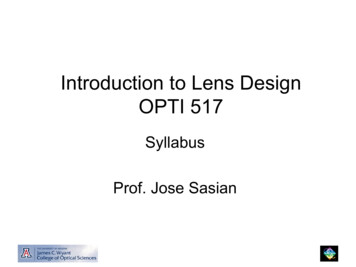
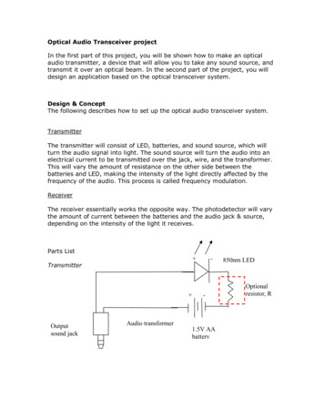
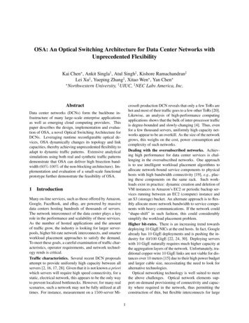
Design and Analysis of Optical Switch for Data Center Networks . . . . 23291. IntroductionThe design of optical switch in data-centers is an important and hot area of research.In optical data, center networks at many places switches are used to connect variouslevel of hierarchy. The optical switches can be placed in data center networks whereswitching of information is necessary. Moreover, in data centers data rate isdifferent at various switching positions. Therefore, at different positions opticalswitches device can be different. The lowest data rates switches are at the bottomof the hierarchy, which are used to connect ToR to ToR connections (Fig. 1).In recent past, many designs for data-centers have been proposed includingbuffer-less and buffered designs [1-5]. In buffered designs electronic, optical andhybrid, buffers are considered [6]. Buffered designs are more complex whilebuffer-less design are relatively simple [1, 6]. However, buffer designs have betterpacket loss performance [7].Recently O-OFDM is considered as excellent way of transmission for opticalsignal. However, O-OFDM only supports relatively low data rates. Therefore, OOFDM based switches can be used to establish ToR to ToR connections.In typical (non-optical) OFDM systems, the information is transferred using bipolar electrical field signals. For the coherent receiving, a local oscillator alongwith low pass filter is used. However, in optical communication intensity of laseris used for information transfer, which is a positive signal (Uni-polar). On thereceiver, side direct detection is used.The use of O-OFDM in the field of optical data centre design is a novel area ofresearch. In these designs, both optical and electrical parameters need to beconsidered as design parameters. Moreover, design parameters of O-OFDM alsoneed to be investigated.Most of recently proposed designs are based on cyclic AWG router, which is awavelength sensitive routing device, and it is capable of handling multiplewavelengths simultaneously. As AWG is a cyclic device therefore for non-blockingoperation of AWG only a few wavelengths are needed (Fig. 2). In past variousAWG based design, like buffer-less, feed-forward type buffer, feed backward typebuffer, re-circulating type buffer are common. In data, centers where hundreds ofsuch switches would be needed demands for less complex cost effective design. AnAWG is an excellent device as each input is connected to each output via a fixedwavelength, therefore using AWG, one to one and many to one connections arepossible [7, 8]. Moreover mesh connections where all inputs and outputs areconnected is also possible as shown in Fig. 2.In recently proposed design, TWC and AWG based are used to connect ToRswitches as shown in Fig. 3 [5]. First of label extractor (LE) is used to extract thelabel it is processed by controller and as per the information TWC wavelength isselected either for straight path or to put packet inside the buffer. Here in this designbuffer is assumed to be electronic in nature, thus information is stored through O/Econversion and retrieved by E/O conversion again. From here information can besend to correct output by tuning its wavelength through buffer TWC. In this designin a single time slot, only one input connects to one output only and only one packetwill exit the buffer in a single time slot. Moreover, TWC technology is not fullymatured and currently available TWCs are noisy in nature.Journal of Engineering Science and TechnologyAugust 2018, Vol. 13(8)
2330R. Kumar and A. TripathiFig. 1. Schematic of data center networks.Fig. 2. Schematic of cyclic arrayed waveguide optical router.Journal of Engineering Science and TechnologyAugust 2018, Vol. 13(8)
Design and Analysis of Optical Switch for Data Center Networks . . . . 2331To overcome these problems in this paper we have discussed an OFDM andAWG based switch, which is non-blocking in nature, thus no need of buffer insuch arrangement.This paper discusses AWG based switch design for data centers applicationusing OFDM technology. First of all physical layer analysis is performed. It isdiscussed that how ACO-OFDM can be used in data centers. Finally, a hybridmethod is suggested to reduce PAPR significantly.The rest of the paper is organized as follows: in section 2 of the paper, MIMOOFDM in data centre networks is discussed. MIMO-OFDM cyclic optical router isdetailed in section 3 of the paper. In section 4 of the paper BER analysis isperformed. In section 5 of the paper ACO-OFDM is discussed, and in section 6PAPR mitigation techniques are discussed ad finally section 7 of the paperdiscusses major conclusions.Fig. 3. Schematic of optical router based on TWC and AWG.2. MIMO OFDM in Data Centre NetworksIn the case of an OFDM transmitter, serial data streams are collected and mappedinto NC constellation symbols { {S[k ]}kN c 0 1 } by making use of BPSK or QPSK Nppilots are embedded into the data symbols prior to transforming into the timedomain signal by N-orthogonal subcarriers through an IFFT given ass ( n) 1NN 1 S[k ]ej 2 nkN,n 0,1,., N 1(1)k 0At every receiver, a typical photo-detector (PD) receives O-OFDM signals fromvarious input sources on different optical wavelengths, with no conflict in theOFDM subcarriers and the used WDM wavelengths. This is known as parallelsignal detection (PSD) technique [9], and this technique has been shown in OFDMWDM-based optical networks [9].In optical transmission, we have two kinds of OFDM execution. The first kindis of the electrically creation of the OFDM signal and modulation of the signal toJournal of Engineering Science and TechnologyAugust 2018, Vol. 13(8)
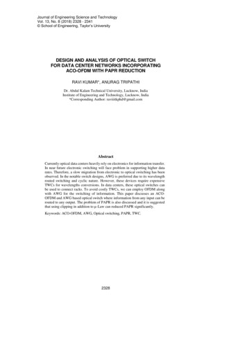
2332R. Kumar and A. Tripathian optical carrier [10-12]. This kind of execution is termed as optical OFDM(OOFDM). There is an option for the receiver to make use of either direct detectionor coherent detection strategies. The next kind is to develop the orthogonalsubcarriers (otherwise known as tones) optically and after that make an applicationof a signal onto each subcarrier [12]. This is known as the all-optical OFDM (AOOFDM).3. Mimo-OFDM Cyclic Arrayed Waveguide Optical RouterThe ToR switches may require to connect with severs or switches in theseconnections; a low bit rate link is desirable which can be achieved using MIMOOFDM system as shown in Fig. 4. The ACO-OFDM based switch consists of Nracks, which are connected by ToR switch. Each of the rack contains multipleservers. The communication among different ToR is accomplished using DCN.The signals from different racks are combined at each rack and send to atransmitter consisting OFDM modulator, which converts the aggregatedinformation to j subcarriers and these subcarriers, are converted into j WDM signalsusing DML. It is noticeable that 0 j N. These WDM signals are detected by PDsat each output port of AWG and after OFDM demodulation process directedtowards output ToR. It is noticeable that each photo-detector can detect multiplesignals using PSD technology. In this technology, more than one signal can bedetected simultaneously using array of detectors.Fig. 4. Schematic of MIMO- OFDM cyclic arrayed waveguide optical router.The DCN design depends on an O-OFDM execution. It shows network levelMIMO operation in light of the fact that all racks are able to transmit the similarOFDM signal to various goal racks at the same time, and numerous racks are able totransfer the signal to the same particular rack in the meantime by modulating data onvarious OFDM subcarriers. In DCN, distance between the ToR switches is in theJournal of Engineering Science and TechnologyAugust 2018, Vol. 13(8)
Design and Analysis of Optical Switch for Data Center Networks . . . . 2333range of a few tens of meters to 2 km [4]. Therefore, fiber optic degradation like pulsebroadening, jitter, and polarization mode dispersion will not come into picture.4. BER AnalysisIn this design from DML to PDs signal propagates in optical domain. The powerbudget analysis is essential to know about the minimum power requirement for thecorrect operation of the switch. The loss in signal power when packet directlypasses through the switch isAL LDML LMUX LAWG(2)Thus power available at the output of the optical switch isPout (b) ALbPinb [0,1](3)At the receiver, both shot and thermal noises are present, and for the bit {b ε (0,1)} the noises at the optical receiver are [13, 14]:Shot noise: s2 2qRPBe and thermal noise: th2 4K BTBeRLThe total noise variance is 2 b s2 th2(4)The Bit Error Rate (BER) can be obtained as I 1 I 0 P 1 P 0 BER Q Q R 1 0 1 0 where Q(.) is error function and defined asQ z 12 e z22(5)dz .(6)zUsing the above formulations and value of different parameters as given inTable 1, results are shown in Figs. 5 and 6.Table 1. List of parameters and their values.ParametersElectronic ChargeResponsivityElectrical bandwidthOptical bandwidthLoss of AWG (32 channels)Loss of DMLLoss of MUXBoltzmann ConstantLoad ResistancePlanck ConstantValue1.6 10-19 C1.28 A/W20 GHz40 GHz3.0 dB1 dB3.0 dB1.38 10-23 m2 kg s-2 K-150 Ω6.6 10-34 J-sIn Fig. 5, BER vs. optical and electrical powers is shown. Here, received poweris 7 dB below to the transmitted power. BER of 10-9 is obtained for receivedJournal of Engineering Science and TechnologyAugust 2018, Vol. 13(8)
2334R. Kumar and A. Tripathipower of -17.46 dBm, thus corresponding transmitted power is -10.46 dBm. Forslight increase in power to -17dBm, the obtained BER 10-12. For BER of 10-9 theOSNR (optical signal to noise ratio) is 7.9 dB and ESNR (electrical signal to noiseratio) is 15.8 dB.In single carrier system, information is transmitted in form of bits using singlecarrier only, while in multi-carrier system, more than one carrier are used forinformation transfer. OFDM is also a multi-carrier transmission technology, wheremultiple carriers known as sub-carrier used for information transfer. However, inOFDM each sub-carrier carries data from a common source only. Due to themultiple carries inclusion via IFFT, OFDM signal in time domain have high peakto-average power ratio (PAPR)Fig. 5. BER vs. optical transmitted and received powers.Fig. 6. BER vs. optical and electrical SNR.Journal of Engineering Science and TechnologyAugust 2018, Vol. 13(8)
Design and Analysis of Optical Switch for Data Center Networks . . . . 2335In optical communication, two variants of OFDM namely DC-biased opticalOFDM (DCO-OFDM) and asymmetrically clipped OFDM (ACO-OFDM) areused. Both these techniques satisfy Hermitian symmetry. In DCO-OFDM all thesub-carriers carries information while in ACO-OFDM only odd subcarriers carryinformation. In DCO-OFDM to clip negative part DC biased is added which leadto distortion and in-efficient detection system. Therefore, in this work ACOOFDM is used.5. ACO-OFDMThe ACO-OFDM system transmitter is shown by the Fig. 7 [12]. Data symbolsare carried by the only the odd subcarriers in ACO-OFDM, while as far as theeven subcarriers are concerned, they are set to zero, i.e., Sk 0 for k 0, 2, 4,.,N-2. Meanwhile, ACO-OFDM additionally fulfils the Hermitian symmetry, i.e.,Sk SN-k in the frequency domain and consequently contains the accompanyingframe structure.Fig. 7. Block diagram of aco-ofdm transmitter mechanisms. S 0, S1 , 0,.S N ,.0, S1 . 1 2 (7)After the IFFT, we have the time-domain signal for n 0,., N - 11sn NN 1 S ek 0k2 knj N2 NN 12 Re Sk e j k 1 2 knN 2 N 2 2 t 1 n j NRe S2t 1e t 1 N /4It must be noted here that the time-domain signal of ACO-OFDM hasaccompanying symmetric property:sn N22 N N 2 2 t 1 n 2 N .N jReS.e 2t 1 sn , n 0,., 1 2t 1 N /4(8)Consequently, it is clear that anyone can make the transmission of the positivepart of sn and can also clip its negative part without making any sort of change ininformation. We can represent this kind of clipping process along with the upperbound limit asJournal of Engineering Science and TechnologyAugust 2018, Vol. 13(8)
2336R. Kumar and A. Tripathi cu , s Clip sn sn , 0, sn cu0 sn cucn(9)sn 0cDue to the fact that sn is nonnegative, we do not require to make addition of aDC bias. After this, we convert the clipped signal into the continuous signal s c t for making the transmission through a laser.In Fig.8, BER analysis of ACO-OFDM under QPSK and 8-PSK modulationschemes is shown. Here the BER performance of QPSK scheme is much betterin comparison to 8-PSK. Still under both the schemes at low ESNR verylow BER is possible. Therefore, to meet BER criterion for OFDM part andoptical part a proper transmitted power should be selected for both analog andoptical transmission.Fig. 8. BER analysis of ACO-OFDM under QPSK and 8-PSK modulation schemes.In OFDM systems, PAPR is other important issue, which should be addressed.PAPR is calculated as ratio of maximum power of a signal to its average power [15]:PAPR .E s max sn22(10)nwhere E denotes expected value. In case of large number of sub-carriers this is acommon phenomenon and cannot be avoided. However, to mitigate suchdetrimental effect a few schemes are proposed as discussed in next section.6. PAPR Mitigating TechniquesIn this Section, various PAPR mitigation techniques are discussed. Thesetechniques have been modified in the paper to meet ACO-OFDM requirements andoptical communication.Journal of Engineering Science and TechnologyAugust 2018, Vol. 13(8)
Design and Analysis of Optical Switch for Data Center Networks . . . . 23376.1. Clipping and filteringGenerally, clipping is performed at the transmitter side. In this method, amplitudesof the bins, which are above than pre-defined threshold are, clipped (Fig. 9). Thisclipping reduces the variability in the amplitudes for PAPR reduces. However,clipping of signals introduces both in band distortion and out of band radiation intoOFDM signals, thus BER performance also degrades.Fig. 9. Block diagram of clipping.Filters are used to cut out of band radiation after clipping however; it cannotreduce in-band distortion. However, due to clipping and filtering some peak mayre-growth. This can be understood asLNy[n] x[k ]h[n k ](11)k 0where y[n] is output after filtration process, x[n] is OFDM symbol, h[n] is filterresponse, L is channel length and N is number of OFDM symbols. Due to theconvolution sum, the amplitude value increases. In the considered design (Fig. 4),AWG itself is a wavelength sensitive device, thus, it will eliminate out of bandnoise without affecting the amplitude levels of inband symbols. Thus in OOFDMthe dis-advantage of filter removed completely.6.2. µ-Law MappingCompanding techniques are no-linear techniques, which reduces the variability inthe amplitudes of the bins [16]. In the companding techniques bins whoseamplitudes are smaller get amplified however, if amplitude is higher than certainthreshold it remains nearly same. Thus, variability in the amplitude gets reduced.In the µ-law companding, signal is squeezed at the transmitter consideringformula: sn max( sn ) ln 1 max( sn ) sn' ln(1 )(12)where µ is the µ-law compression parameter. At the receiver site µ-law signal isexpands as:' ln(1 )max( sn ) sn max( sn ) sn 1 e (13)Figure 10 demonstrates the µ-OFDM system building blocks. We candifferentiate O-OFDM and RF-OFDM in the way of signal transmission. In OOFDM real and imaginary parts are separated and only positive signals areJournal of Engineering Science and TechnologyAugust 2018, Vol. 13(8)
2338R. Kumar and A. Tripathitransmitted. After this, µ-law mapping is performed. Now at this point,E/O conversion data is converted into optical domain and transmitted. Thansignal is passed through optical channel, and inverse process is repeated atthe receiver.In this work, we have proposed a hybrid scheme where both µ-law compandingscheme and clipping based scheme is proposed where filtering action will beperformed by AWG.Fig. 10. µ-law based optical OFDM system.In Fig. 11(a), normal ACO-OFDM signal plot in terms of amplitude vs. binis shown. Here bin represents index value. In figure, a large variation inamplitude is observed. The maximum observed value is 0.0537 and minimumobserved value is 6.5 10 -4. To tackle this large variation clipping is used andobserved results are shown in Fig. 11(b). Here, if particular bin value is higherthan 0.7 maximum amplitude value than it is bring down to 0.7 maximumamplitude value, thus bin values above this are clipped. Now the maximumvalue is 0.0376.In Fig. 11(c) µ-law based ACO-OFDM signal plot in terms of amplitude vs. binis shown, with maximum amplitude as 0.0805 and minimum value as 0.0405.However, using µ-law the variation in amplitude gas reduced significantly. In Fig.11(d) µ-law, clipped and ACO-OFDM signal plot in terms of amplitude vs. bin isshown. Here, in comparison to Fig. 11(a), the variation in amplitude has reducedsignificantly, and after inversing mu-law original signal can be recovered.It is clear from Figs. 12 that as bin size reaches to a value of 1000, PAPR valuesstabilizes. The PAPR of generated ACO-OFDM is nearly 26 dB, which reduces to19 dB with clipping. While using mu-law, PAPR reduces to nearly 5 dB, whichnow with clipping reduces to 1.3 dB. This reduction in PAPR is possible due to theAWG, which works as filter, and additional filter is not needed after clipping.Therefore, amplitude is stabilized and multi-stage clipping and filtering is notrequired as in case of separate filtering amplitude of the signal increases due toconvolution effect.Journal of Engineering Science and TechnologyAugust 2018, Vol. 13(8)
Design and Analysis of Optical Switch for Data Center Networks . . . . 2339(a) ACO-OFDM signal plot interms of amplitude vs. bin.(c) µ-law based OOFDM signal plotin terms of amplitude vs. bin(b) Clipped ACO-OFDM signal.(d) µ-law and clipped basedOOFDM signal plot.Fig. 11. Performance of ACO-OFDM under different scenarios.Fig. 12. Comparison of PAPR reduction techniques.7. ConclusionsThis paper presents an analysis of optical switch design for DCN, which is basedon MIMO-OFDM technology. The considered design provides error free and non-Journal of Engineering Science and TechnologyAugust 2018, Vol. 13(8)
2340R. Kumar and A. Tripathiblocking performance among ToR switches. To meet optical requirements ACOOFDM is considered. BER performance for both optical and ACO-OFDM isevaluated. The problem of PAPR is also highlighted, and solutions are suggestedto improve the performance. Simulation study is performed to obtain PAPR underdifferent schemes. It has been found that the proposed scheme is much superior incomparison to other considered schemes.NomenclaturesALbBeI𝐿 BRLTotal LossBitElectrical BandwidthPhoto-currentLoss of TWC, dBLoss of Multiplexer dBLoss of Arrayed Waveguide Gratings, dBNumber of sub-carriersElectronic ChargeError FunctionSub-carrierTemperatureBoltzmann ConstantLoad ResistanceGreek SymbolsVarianceσ FAIFFTLEMIMOOFDMPAPRPDPSDQPSKToRTWCWDMAsymmetric Clipped Optical Orthogonal Frequency DivisionMultiplexingArrayed Waveguide GratingsBit Error RateBinary Phase Shift KeyingDirect CurrentData Centre NetworksDirect Modulated LaserErbium Doped Fiber AmplifierInverse Fast Fourier TransformLabel ExtractorMultiple Input Multiple OutputOrthogonal Frequency Division MultiplexingPeak to Average Power RatioPhoto-detectorParallel Signal DetectionQuadrature Phase Shift KeyingTop of RackTunable Wavelength ConvertorWavelength Division MultiplexingJournal of Engineering Science and TechnologyAugust 2018, Vol. 13(8)
Design and Analysis of Optical Switch for Data Center Networks . . . . 16.Ye, X.; Yin, Y.; Yoo, S.B.; Mejia, P.; Proietti, R.; and Akella, V. (2010). DOS:A scalable optical switch for datacenters. Proceedings of the 6th ACM/IEEESymposium on Architectures for Networking and Communications Systems, LaJolla, CA, USAShukla, V.; Jain, A.; and Srivastava, R. (2016). Design of an arrayedwaveguide gratings based optical packet switch. Journal of EngineeringScience and Technology (JESTEC), 11(12), 1705-1721.Shukla, V.; Jain, A.; and Srivastava, R. (2016). Performance evaluation of anAWG based optical router. Optical and Quantum Electronics, 48(1), 69.Yin, Y.; Proietti, R.; Nitta, C.J.; Akella, V.; Mineo, C.; and Yoo, S.J.B. (2013).AWGR-based all-to-all optical interconnects using limited number ofwavelengths. Proceedings of the 2003 Optical Interconnects Conference, 47-48.Yin, Y.; Proietti, R.; Ye, X.; Nitta, C. J.; Akella, V.; and Yoo, S. J. B. (2013)LIONS: An AWGR-based low-latency optical switch for high performancecomputing and data centers. Journal of Selected Topics in QuantumElectronics 19(2), 3600409-3600409.Wang, J.; McArdle, C.; and Barry, L.P. (2016). Optical packet switch withenergy-efficient hybrid optical/electronic buffering for data center and HPCnetworks. Photonic Network Communications, 32(1), 89-103.Rastegarfar, H.; Leon-Garcia, A.; LaRochelle, S.; and Rusch, L.A. (2013).Cross-layer performance analysis of recirculation buffers for optical datacenters. Journal of Lightwave Technology, 31(3), 432-445.Srivastava, R.; and Singh, Y. N. (2010). Feedback fiber delay lines and AWGbased optical packet switch architecture. Journal of Optical Switching andNetworking, 7(2), 75-84.Luo, Y.; Yu, J.; Hu, J.; Xu, L.; Ji, P. N.; Wang, T.; and Cvijetic, M. (2007).WDM passive optical network with parallel signal detection for video and datadelivery. Optical Fiber Communication and the National Fiber OpticEngineers Conference, 2007. OFC/NFOEC 2007, 1-3.Lowery, A.; Du, L.; and Armstrong, J. (2007). Performance of optical OFDMin ultralong-haul WDM lightwave systems. Journal of Lightwave Technology,25(1), 131-138.Shieh, W.; Bao, H.; and Tang, Y. (2008). Coherent optical OFDM: Theory anddesign. Optics Express, 16(2), 841-859.Dissanayake S.D.; and Armstrong J. (2013). Comparison of ACO-OFDM,DCO-OFDM and ADO-OFDM in IM/DD systems. Journal of LightwaveTechnology, 31(7), 1063-1072.Srivastava, R.; Singh, R.K.; and Singh, Y.N. (2009). Design analysis of opticalloop memory. Journal of Lightwave Technology, 27(21), 4821-4831.Olsson, N. A. (1990). Lightwave system with optical amplifiers. Journal ofLightwave Technology,7(7), 1071-1082.Popoola, W.O.; Ghassemlooy, Z., and Stewart, B.G. (2014). Pilot-assistedPAPR reduction technique for optical OFDM communication systems.Journal of Lightwave Technology, 32(7), 1374-1382.Hasan, M.M. (2014). A new PAPR reduction scheme for OFDM systems basedon gamma correction. Circuits, Systems, and Signal Processing, 33(5), 1655-1668.Journal of Engineering Science and TechnologyAugust 2018, Vol. 13(8)
Journal of Engineering Science and Technology August 2018, Vol. 13(8) 1. Introduction The design of optical switch in data-centers is an important and hot area of research. In optical data, center networks at many places switches are used to connect various level of hierarchy. The optical switches can be placed in data center networks where