Transcription
092680 RevDVS OmniPool Automation ControlInstallation ManualContentsBefore you iguration.22HL32950VSP HL32900VSPHL2350020VSP HL2670020VSPHayward Pool Products620 Division Street, Elizabeth NJ 07207Phone (908)-355-7995www.hayward.comUSE ONLY HAYWARD GENUINE REPLACEMENT PARTS
FCC StatementThis device complies with part 15 of the FCC rules. Operation is subject to the following two conditions:(1) This device may not cause harmful interference, and (2) this device must accept any interferencereceived, including interference that may cause undesired operation.Changes or modifications not expressly approved by Hayward could void the user’s authority tooperate this equipment.NOTE: This equipment has been tested and found to comply with the limits for a Class B digital device,pursuant to Part 15 of the FCC Rules. These limits are designed to provide reasonable protectionagainst harmful interference in a residential installation. This equipment generates, uses and canradiate radio frequency energy and, if not installed and used in accordance with the instructions, maycause harmful interference to radio communications. However, there is no guarantee that interferencewill not occur in a particular installation. If this equipment does cause harmful interference to radioor television reception, which can be determined by turning the equipment off and on, the user isencouraged to try to correct the interference by one or more of the following measures:-- Reorient or relocate the receiving antenna.-- Increase the separation between the equipment and receiver.-- Connect the equipment into an outlet on a circuit different from that to which the receiver isconnected.-- Consult the dealer or an experienced radio / TV technician for help.Industry Canada StatementThis Class B digital apparatus complies with Canadian ICES-003.Cet appareil numérique de la classe B est conforme à la norme NMB-003 du Canada.The term “IC” before the certification / registration number only signifies that the Industry Canadatechnical specifications were met.1USE ONLY HAYWARD GENUINE REPLACEMENT PARTS
Table of ContentsBefore you Begin.3Overview.4MountingVS Hub.7Control Pad.7Smart Relay.8Temperature Sensors.9Plumbing.9Electrical WiringHigh Voltage.11Low Voltage.13System Startup.22ConfigurationPre Programmed Configuration.25Typical Configuration.25Advanced Configuration.27Quick Edit.42Control Pad Mounting Template.502USE ONLY HAYWARD GENUINE REPLACEMENT PARTS
Before you BeginWhat’s IncludedCheck that the following components have been included in your package: VS Omni HubControl PadSmart Relay2 Temperature SensorsVariable Speed Pump (VSP)15 ft, 3 conductor (red, black and bare wire) communication cable to connect Hub to VSP2 Wiring Whips - 6 ft flexible conduit containing three 12AWG conductors (red, black andgreen) for wiring VSP to VS Omni Hub and for Smart Relay installation). A length of white 12AWG conductor is included to replace red for 115V Smart Relay applicationsInput Power Wiring harness and miscellaneous installation hardwareWhat’s NOT IncludedSome of the additional items that you may need to complete an installation include:WireWire/conduit for incoming powerWire for remote heater control and other low voltage devicesEthernet cable (if not using wifi)MiscellaneousValve actuator to automate pool functions (see page 9)Flow switch for pump protection/flow monitoringMounting hardware for mounting Hub, Control Pad and Smart RelayCable/cord connectors to provide knockout strain reliefWire nut connectorsUSB thumbstick (to update firmware)Tools NeededPhilips and flat screwdriversWire cutters and strippersKnife to cut conduitDrill and drill bits (including 3/8")PliersLevelAccessory Products - Order SeparatelyHLH485RELAYFLOGVA-242PCSmart Relay used for controlling additional pool equipmentFlow Switch used to detect water flowValve ActuatorTemperature Sensor for 3rd input3USE ONLY HAYWARD GENUINE REPLACEMENT PARTS
OverviewThe Hayward VS Omni is a web enabled pool automation control with a convenient touchscreeninterface. Because it's packaged with a high efficiency variable speed pool filter pump, the VS Omniis ideal for both retrofit and new pool/spa installations. Automatically and remotely control pumps, aheater, a valve actuator, pool and yard lighting, and more. The VS Omni offers the next generation oftechnology to manage pool/spa equipment, allowing communication to web connected computersand mobile devices. You can now conveniently monitor your pool/spa and change settings anytime,and from anywhere.Please read through this manual thoroughly before attempting to install, configure or operate thisunit. A Quick Start guide is also included to offer concise information to experienced installers.FeaturesThe standard Hayward VS Omni offers the following functionality: controls up to 2 variable speed pumps for pool/spa filtration and water features controls up to 2 Smart Relays to turn on/off single speed pumps, pool lights, yard lights, waterfeatures, chemical dispensers and more controls up to two valve actuators allowing you to manage two bodies of water (both pool andspa) or can be used for water features, cleaners, solar heating, etc. (currently requires Hub to bepowered by 230 VAC) controls one conventional heater (electric heatpump or gas) and optional solar heater (for singlebody of water applications only) inputs for up to 3 temperature sensors or external input devices built-in wireless to connect to the home’s router/access point (ethernet port provided for optionalwired connection) optional flow switch used to protect pool equipment by detecting water flowOptional accessories (page 3) can expand the functionality of the VS Omni. Determine your needsand select the necessary accessories before you begin the installation.EquipmentVS Omni HubAll incoming/outgoing wiring will be connected to the Hub. The VS Omni Hub can be powered byeither 230 VAC (required if using actuators) or 115 VAC. Input power should be constant, not froma timer. If a timer must be used, set the timer to power the Hub continuously. For convenience, a 6ftWiring Whip is included with the VS Omni. This whip is intended to connect the Hub's input powerto the variable speed pump if using 230 VAC. This connection should be made inside of the Hub andwill ensure that both the Hub and pump are powered continuously.The remaining connections, including the Control Pad, are all low voltage. Depending on your installation, these connections could be to a heater, Smart Relays, temperature sensors, actuator and aflow switch.4USE ONLY HAYWARD GENUINE REPLACEMENT PARTS
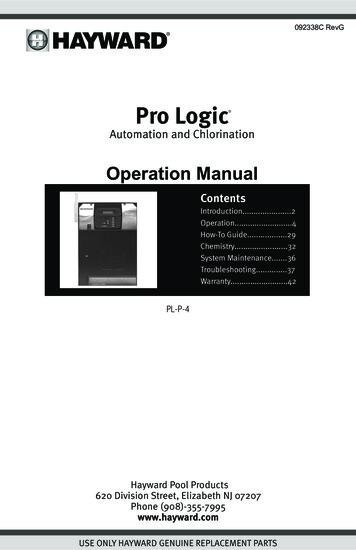
Control PadThe Control Pad is weather resistant and comes with a 15 ft cord. Its resistive touch screen withflip down cover is designed to function year round directly in the elements. Because it plugs into theHub, it should be mounted close by, but in a location that is convenient for the user to periodicallyview and change pool/spa settings.The Control Pad features a USB connector for firmware updates and an Ethernet connector for anoptional direct connection to your router (if wifi won't be used).Smart RelaySmart Relays have 15 ft cable that wire to the Hub. They're used to control high voltage 115 or 230VAC pool equipment like lights, water features, pumps and more. Power to the intended load mustbe supplied separately and run through the Smart Relay. Smart Relays are rated for up to 20 ampsat 230 volts.Temperature SensorsDepending on your installation, up to 3 temperature sensors may be used. The VS Omni requiresa water temperature sensor for heater operation. If freeze protection is desired, an air temperaturesensor is also required. For solar heating systems, a solar sensor is necessary. Even if your installation doesn't require the use of temperature sensors, installing water and air sensors provides aconvenience to the user, especially during remote use.Flow Switch (not included)An optional flow switch can be used to detect leaks or clogs in the pool/spa plumbing.(Optional)Smart Relay 2Wiring HubControl PadSmart Relay 1REMOTEREMOTERELAYRELAYOFFLINE:ON/OFFInput Power orExisting TimeclockWirelessConnectionOREthernet toRouterInputPowerComm. to SmartRelay 2 (15’)Comm. toController (15’)Wiring WhipPowerto VSPif samevoltageas HubOFFLINE:ON/OFFTo Feature,Accessory,Lights, etc.To Feature,Accessory,Lights, etc.Comm. to SmartRelay 1 (15’)Sensor 1(Water Temp.)Input Power toSmart Relay 1Sensor 2(Air Temp.)Comm. toValve ActuatorComm.to VSPComm. toHeaterTo SolarFilterSensor 3 (Solar ORExternal Input)Heater(Optional)Flow SwitchValveActuatorVariableSpeed PumpFROMPOOLTOPOOL5USE ONLY HAYWARD GENUINE REPLACEMENT PARTS
InstallationInstallation StepsDANGER of Death, Injury or Property Damage if procedure not followed. Power wiring mustbe shut off before attempting to install the VS Omni.The VS Omni is designed to be mounted outdoors at the pool pad. Both the Hub and the ControlPad are water resistant and can be left out for the winter. Details on each installation step areshown below:1. Mounting the equipment (page 7)VS Omni HubControl PadSmart RelayTemperature sensorsValve actuators (if applicable)2. Plumbing (page 9)General Pool EquipmentFlow Switch3. Electrical Wiring (page 10)Hub powerGroundingLow voltage wiring (Pool Pump Communication, Heater, Smart Relays, Temperature Sensors,Flow Switch, etc.)5. System Startup and Firmware Upgrade (page 22)The most common installation technique is described in the included Quick Start Guide. Use thisguide if possible. If the Guide can not be applied to your particular installation, refer to the additionalinformation in this manual.6USE ONLY HAYWARD GENUINE REPLACEMENT PARTS
Mounting the EquipmentVS Omni HubThe Hub is contained in a raintight enclosurethat is suitable for outdoor mounting. It mustbe mounted a minimum of 6 ft (2 meters) horizontal distance from the pool/spa (or more, iflocal codes require). The Hub is designed tomount vertically with the knockouts facingdownward. Do not mount the Hub inside apanel or tightly enclosed area.When selecting a location, note that the standard cables supplied with the optional flowswitch, temperature sensors, and actuatorsare all 15 ft (5m) long. Additional low voltage connections will have to be made to thepump and/or heater. 230 VAC (required if using actuators) or 115 VAC input power mustalso be run to the Hub. Try to mount the Hub ina location where incoming/outgoing wiring willbe easily accessible.Mount the Hub on a wall or flat surface. Selectmounting hardware that is appropriate for the mounting surface and material. The Hub has twokeyhole type mounting tabs on the top and bottom of the enclosure requiring a total of 4 fasteners.Control PadThe Control Pad comes with a 15 ft cord and plugs into the Hub. It should be mounted in a locationthat is convenient for the user to view and change pool/spa settings. When considering the mounting location, make sure there is enough clearance above the enclosure so that the flip door will beable to be opened fully. Also be sure to allow enough clearance below the Control Pad to accessthe USB and Ethernet connectors. For best viewing results, position the Control Pad where it won'tbe subjected to direct sunlight.The Control Pad has two keyhole cutouts on the back of its enclosure. To mount, screw the twoprovided fasteners into the mounting surface at the desired location using the template found onpage 54 . Tighten until the bottom of the screw heads are 1/8" off the mounting surface. Positionthe Control Pad cutouts over the screw and slide the unit downward. You may have to tighten orloosen the screws slightly to fully engage the screw heads to get a snug fit.7USE ONLY HAYWARD GENUINE REPLACEMENT PARTS
Smart RelayThe Smart Relay is packaged with a single gang electrical box but can also be used with any existingcomparable standard electrical box with a minimum volume of 16.2 in3. If using 115 VAC, makesure that there is a Neutral line inside the box before installation. If not, you must run a separateNeutral wire to power the Smart Relay. This is not a concern if using 230 VAC. Note that conduit andconnections to the included plastic box must be non-metallic.Find a location within 15 ft of the Hub with convenient access to the pool equipment that you intendto control with the Smart Relay. Three threaded 1/2" NPT knockouts are provided for high voltagepower coming into the relay and for power out to the pool equipment. A Wiring Whip is included toaid installation.The Smart Relay has a manual On/Off button that can be used if communication is lost with the Hub.Although this button is not functional during normal operation, mount the Smart Relay in an accessible location to use this feature in case of communication loss.Mount the Smart Relay to a wall or other flat surface using the mounting holes which are designedto accommodate #8 screws.8USE ONLY HAYWARD GENUINE REPLACEMENT PARTS
Temperature SensorsWater SensorThis sensor is used to measure the pool/spa temperature and is installed in the filtration plumbingafter the filter but before either the solar or conventionally fueled heaters.1.2.3.Drill a 3/8” (10mm) diameter hole in the PVC piping and remove all chips and burrs.Insert sensor until O-ring collar sits flush on the hole.Position hose clamp over the sensor and gently tighten until O-ring makes an adequate seal.Do not overtighten.Air SensorMount the air sensor outdoors. IMPORTANT: The air sensor must not be mounted in direct sunlight.Solar SensorFor solar applications, mount the sensor near the solar collector array so that it is exposed to thesame sunlight as the collectors. Use additional cable (20 AWG) if necessary.Optional Valve ActuatorsCurrently, using an Hayward GVA-24 actuator or equivalent requires that the Hub be powered with230 VAC. If powering the VS Omni Hub with 115 VAC, an actuator can't be used. For installation,refer to the mounting instructions included with the unit. After configuring and first operating thevalve, note that the internal cams in the actuator may have to be adjusted depending on the way theactuator is mounted on the valve and the desired valve action.PlumbingOptional Flow SwitchOnly applicable if leak/clog detection is desired. The flow switch should be plumbed on the returnside at the very end of the pool pad plumbing. This will ensure that if a leak occurs anywhere at thepool pad, the VS Omni will be able to detect it. Understand that if a leak occurs after the flow switch(downstream), the VS Omni will not sense a no flow condition.IMPORTANT: There must be at least a 12” (30cm) straight pipe run before (upstream) the flow switch.IMPORTANT: To ensure proper operation, verify that the arrow on the flow switch points in the direction of water flow.Variable Speed PumpRefer to the included VS Omni Pump manual for plumbing information.9USE ONLY HAYWARD GENUINE REPLACEMENT PARTS
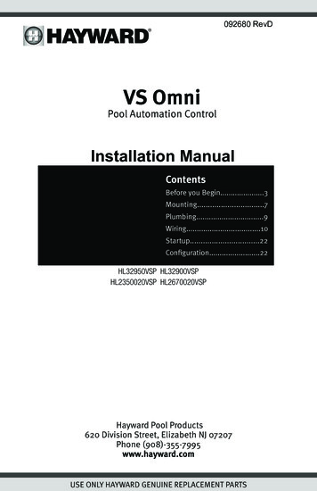
Electrical WiringThe Hub requires both high and low voltage connections. Always:- Ensure that Power is disconnected prior to performing any wiring- Follow all local and NEC (CEC if applicable) codes- Use copper conductors onlyA dedicated channel on the right side of the Hub has been provided for all low voltage wiring. All lowvoltage wires should run through this channel to exit the Hub. A weather resistant gasket is provided(see page 21) to seal this exit.Temperature Sensors,External Input& HeaterSmart Relays&Variable Speed PumpCommunicationControl PadValve ActuatorsFlow SwitchInput PowerLow VoltageWiring Channel(Hub must be powered by230 VAC)Ground Screw10USE ONLY HAYWARD GENUINE REPLACEMENT PARTS
High Voltage WiringHub Input PowerThe Hub requires a constant 230 VAC (required if using actuators) or 115 VAC input power to operate. A wiring harness is included and will plug into the input power connector shown on page 10.Wire the harness according to the diagram below.L2NL1L1230 VAC115 VACFor easy installation, if replacing an existing 230 VAC pump, disconnect power at the pump and usethat connection to provide power to both the Hub and the new variable speed pump (VSP). Use theincluded Wiring Whip to aid in this connection. The diagram below shows an existing timeclock usedto power the old pump. This configuration can be easily modified to power the VS Omni and the newVSP. Refer to the diagrams below.Existing Timeclock230 VACDisconnect from existing230 VAC pumpL2Connect to Hub andnew Variable SpeedPump (VSP)L1GroundWiring Whip toVSP11USE ONLY HAYWARD GENUINE REPLACEMENT PARTS
If replacing a 115 VAC pump, you can disconnect power at the pump and use it to power the Hubonly. The new variable speed pump however, requires 230 VAC which will have to be run separately.Refer to the included pump manual for input power wiring.115 VACDisconnect from existing115 VAC pumpNeutralL1Connect 115 VAC to Hubonly and run 230 VACseparately to the newVSPGroundIf using an existing timeclock to power the Omni VS Hub, set it to run constantly. If the VS Omni Hubwill be connected to a panel or switch, the power will have to be left on continuously.GroundingConnect a ground wire from the primary electrical panel to the Hub's ground connection as shown inthe previous diagrams. Also ground each piece of high voltage equipment that is connected throughthe Hub or Smart Relay.Variable Speed Pump Input PowerThe VS Omni pump requires a constant 230 VAC, 60Hz input power whether from the VS Omni Hubusing the Wiring Whip or directly from a service panel/switch. Refer to the VS Omni Pump manual forthe location of the wiring terminals as well as other related high voltage wiring information.12USE ONLY HAYWARD GENUINE REPLACEMENT PARTS
Smart Relay Load WiringA Smart Relay can be used to control either 115 or 230 VAC pool equipment. The relay is double pole(makes/breaks both “legs” of 230V circuits or one "leg" of 115V circuits). Refer to the diagram belowfor wire connections. Use the included Wiring Whip if the supplied electrical box will be mountedwithin 6 ft of the power source. Red, black and green conductors are included for 230 VAC and awhite conductor is supplied if using 115 VAC input power. Use the included wire nuts for wiring connections. Use proper threaded strain relief fittings for conduit attached to knockouts. After wiring iscomplete, carefully insert the cover with connections into the box and secure.Smart RelayWire Colors115 VACLine inBlack230 VACLine 1 inLoad outBlack/WhiteLoad 1 outNeutralGrayNo ConnectionRedConnect Gray &Red to Line 2 inNo ConnectionRed/WhiteLoad 2 outNeutralLine 1 inLoad 1 outLine 1 inLoad 1 outNeutralLoad 2 outBlack/WhiteRedLine 2 inBlack/WhiteBlackBlackRed/WhiteGray115 VACRedRed/WhiteGray230 VACLow Voltage WiringNote: There is a low voltage channel on the right side of the Hub's enclosure labeled on page 10and shown on page 21. All low voltage wiring that exits the Hub must run through this channel. Theincluded foam gasket (page 21) should be used to seal the channels's exit after wiring is complete.Do not run low voltage wiring through a knockout or with any high voltage wiring.13USE ONLY HAYWARD GENUINE REPLACEMENT PARTS
Hayward Variable Speed Pump (VSP) WiringA separate VSP pump manual has been included with the VS Omni. For low voltage communicationwiring information, refer to the pump manual.Smart RelaysLike VSPs, Smart Relays rely on communication from the Hub. Their 4 conductor cable is wired tothe same connector as a VSP. Wire the cable as shown below. Up to two Smart Relays can be controlled by the VS Omni. In addition to communication wiring, the Smart Relay will be wired to highvoltage pool equipment shown on page 13.GreenWhiteBlackRedSmart Relay ConnectionValve ActuatorsWhen wired for 230 VAC, the VS Omni can control up to two valve actuators which allow automatedcontrol of pool/spa, water features, cleaners or solar heating. The VS Omni is compatible with standard valve actuators manufactured by Hayward, Pentair/Compool, and Jandy. Actuators have 15 ftcables that are terminated with connectors that plug directly into the Hub as shown on page 10.Temperature SensorsThe Hub utilizes 10K ohm thermistor type sensors with 15 ft cable. If a longer cable is required, contact the Hayward service dept. (908-355-7995) for information on suitable cable types and splices.Temperature sensors are wired to the 8 position connector shown on page 10 and on the following page. To unlock, push on the corresponding lever with a small tool as shown. When pushed,the connector will be open and able to receive the wire lead. For best results, strip back leads 1/8"before inserting. After the wire is fully inserted, release the lever and the wire will lock in place.14USE ONLY HAYWARD GENUINE REPLACEMENT PARTS
Pool/Spa SensorPush on leverAirSensorInsert wire hereOptional Solar Sensor orExternal Input SwitchExternal Input SwitchIf solar heating won't be used, a SPST external switch/device can be connected to this input. Thisnormally open or normally closed on/off external device provides a means to turn the filter pump orother pool equipment on or off when certain conditions exists. Connect the external switch as shownbelow. After properly configuring the VS Omni (see Configuration Wizard), the filter pump and/ordesired pool equipment will be forced on or off when the external device is activated.SPST External SwitchEither Normally Open or Normally Closed15USE ONLY HAYWARD GENUINE REPLACEMENT PARTS
Control PadThe Control Pad has a 15 ft cable with a connector that plugs directly into the Hub as shown onpage 10.Note that there are rubber plugs covering USB port and Ethernet port on the bottom of the ControlPad. The ethernet port is available for those that desire a wired connection to their access point,rather than using the VS Omni's built-in wifi (see page 21). The USB port is only used for firmwareupgrades.Optional Flow SwitchThe 15 ft flow switch cable plugs into the flow switch connector shown on page 10. Ensure that theconnector catch “snaps” in order to provide a reliable connection.HeatersThe manuals supplied with most heaters also include specific wiringinstructions for connecting the heater to an external control (usuallyidentified as “2-wire” remote control). For millivolt or line voltageheaters, contact Hayward Tech support, 908-355-7995. Refer tothe information on the following pages for more details on the connection to several popular heaters. Refer to the diagram below forthe location of heater connections at the Hub.HeaterGeneric Heaters1.2.3.4.Wire heater to 115/230V power source per the instructions in the heater manual. The Hubdoes NOT control the power going to theheater.Wire the Hub dry contact heater outputper the diagram below. Many internalparts of the heater can get very hot--seethe heater manufacturer’s recommendations on the minimum temperaturerating for wires. If no guidance is given,use 105 C rated wire.Set any ON/OFF switch on the heater toON.Kill SwitchSet the thermostat(s) on the heater toThermostatthe maximum (hottest) setting.HeaterIgnition/Valve16USE ONLY HAYWARD GENUINE REPLACEMENT PARTS
Laars Heaters1.2.3.4.5.Turn power off to heater.Remove factory jumper from terminal block.Wire Hub to the heater as shown.Ensure toggle switch is in the ON position.Set heater thermostats to maximum position.to limit switchesremove jumperwhitewhiteFusible LinkHayward Pre-2007 HeatersRefer to the instructions inside of the heater manual for “2-wire Remote Thermostat” operationunder “Remote Control Connections” and the diagram on the following page:1. Turn off power to heater.2. Wire Hub to terminals 1 & 2 (see diagram).3. Leave jumper attached to terminals 4 & 5.4. Move “BYPASS” dipswitch on heater circuit board to “ON” position (up).5. Turn heater power back on.6. Switch heater to either “Pool” or “Spa” (it doesn’t make any difference which is selected, theHub will take control).7. Heater display should be “bO” (for “bypass On).8. Heater will start whenever Hub requests (when Hub “Heater” LED is illuminated).17USE ONLY HAYWARD GENUINE REPLACEMENT PARTS
BYPASSºC ONºF OFFDipswitch located on heatercircuit boardPKWRBKRTerminal block located atelectrical junction boxDo not remove jumperHayward 2007-Current HeatersRefer to the instructions in the heater manual for “2-wire Remote Thermostat” operation under“Remote Control Connections” and the diagram below:1. Turn off power to heater.2. Wire Hub to the heater terminals that have the Orange & White connections (see diagram).3. Turn heater power back on.4. Use the “MODE” key on the heater keypad to put the control into “STANDBY” mode.5. Press and hold both the “DOWN” and “MODE” keys for 3 seconds until the display shows thecode “bo”.6. Be sure to put the heater’s control in either “POOL” or “SPA” mode.7. The Hub will now control the heater.To configure the heater for 2- wire remotethermostat control, use the “MODE” key on theheater keypad to put the control into “STANDBY” mode.Then press and hold both the “DOWN” and “MODE”keys for 3 seconds until the display shows the code “bo”.WhiteWireOrangeWire18USE ONLY HAYWARD GENUINE REPLACEMENT PARTS
Pentair/Purex/MiniMax1.2.3.4.Turn power off to heater.Remove factory installed jumper from the “Ext Switch” connector.Wire Hub to the “Ext Switch” connector as shown below.The wires to the Hub must be separated from any line voltage wires. Failure to follow theseinstructions may cause erratic operation of the heater.5. Set the Power (Thermostat Select) switch to either “Pool” or “Spa”.6. Set the “Pool” and “Spa” thermostats to their maximum settings.RemoveFactory JumperExt.SwitchMINIMAXRaypak RP2100 Pool/Spa Heater1.2.3.4.5.Turn power off to heater.Push the mode button to “spa” mode.Set the temperature to the maximum.Push the mode button to “OFF”.Lastly, plug the prewired connector in the P7 position on the board.IMPORTANT: The heater will display “OFF” when it is being remotely controlled by the Hub. Somehomeowners see the “OFF” display and, thinking this is a mistake, change the mode to “POOL”or “SPA” which then disables the remote control by the Hub. To prevent this: Remove the heaterTouchpad connector (P5) which will disable the touchpad.19USE ONLY HAYWARD GENUINE REPLACEMENT PARTS
BlackOrange StripeOrangeBlack StripeYellow/BlackP7RAYPAK RP2100STA-RITE Heater1.2.3.4.Turn power off to heater.Remove upper jacket and open the control box.Remove the jumper for the “fireman’s switch.Wire to the Hub using wire rated for 105 C ntrolYBTerminalBoardYW120 VSTA-RITE20USE ONLY HAYWARD GENUINE REPLACEMENT PARTS
Home RouterConnection to the web is optional. If web enabled devices such as PCs, laptops, tablets or phoneswill be used to access the VS Omni, an ethernet or wireless connection must be made to the homerouter. For wireless connections, refer to the Configuration section of this manual. For ethernet connections, use outdoor rated Cat5e or Cat6 ethernet cable. Connect one end to the Control Pad andthe other to an available LAN port (not WAN) on the home router. Refer to diagram below.Ethernet portterRouLAN portFinal StepsWith the wiring complete, find the Hub's cover. The inside of the cover is made of foam and containsprecut removable gaskets (shown below) that can be used to seal the low voltage exit. Remove agasket and wrap it around the low voltage wiring at the exit of the Hub. Work the gasket into the exitslot until it is fully sealed then fasten the cover to the Hub.Hub Cover (inside)GasketBottom of Hub Enclosure21USE ONLY HAYWARD GENUINE REPLACEMENT PARTS
System StartupAfter confirming that all wiring has been performed according to NEC and local codes and that theHub is properly grounded, apply power to the VS Omni. The VS Omni will take about 30 seconds tofully start.Firmware UpgradeThe VS Omni's firmware is the basic operating system that runs the unit. The VS Omni was shippedwith the version of firmware that was available at the time of release. There may be a newer versionavailable and if so, we encourage you to upgrade. Also, if you have experienced problems, HaywardTechnical Support may advise you to upgrade your VS Omni's firmware. To upgrade the VS Omnifirmware, refer to the procedure shown in the VS Om
Hayward Pool Products 620 Division Street, Elizabeth NJ 07207 Phone (908)-355-7995 www.hayward.com VS Omni Pool Automation Control Installation Manual