Transcription
APP-058 MCS-MAGNUM Interface to Copeland Digital ScrollAPPLICATION NOTEAPPLICATIONNOTEAPP-XXXAPPLICATION NOTETitle HereAPP-XXXAPP-058Revision 1111/18/15AuthorTitle HereRevisionJohn WalterickRevisionWestonKlebsJustin MulliganDescriptionCreated Application NoteDescriptionUpdated Application NoteRevised Application NoteMCS-MAGNUM Interface ToCopeland Digital ScrollAny questions regarding this release, contact:support@mcscontrols.comMicro Control Systems, Inc. 5580 Enterprise Parkway Fort Myers, Florida 33905Any questionsthis ormation contained in this document has been prepared by Micro Control Systems, Inc. and is copyright MicroControlInc.EnterpriseParkwayunlessFort Myers,Florida33905by MCS.protected 2015.Copyingor Systems,distributingthis5580documentis prohibitedexpresslyapproved(239)694-0089 FAX: (239)694-0031 www.mcscontrols.comInformation contained in this document has been prepared by Micro Control Systems, Inc. and is copyright protected 2015. Copying or distributing this document is prohibited unless expressly approved by MCS.
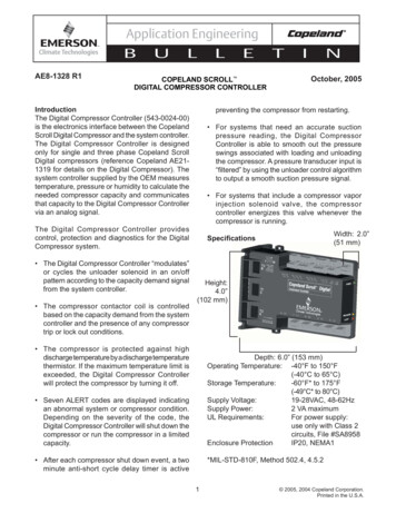
APP-058 MCS-MAGNUM Interface to Copeland Digital Scroll1.General ConceptThis description is intended to aid in the setup of a Copeland Digital ScrollCompressor with a Copeland Digital Compressor Controller in conjunction with aMCS-Controller. The MCS micro controller is used to control compressor capacitywith a PID loop. This loop can be used to control demand % based on a variety ofdifferent sensor readings.2.ChallengesThe Copeland Controller is used in many systems without a main CPU controller. Ithas logic built into the module for controlling the compressor on its own. Because ofthis, careful consideration to time delays and wiring must be taken whenincorporating the controller into an MCS-Controls package. Below is a list of itemsthat should be considered when setting up the config for MCS Controller.2.1 The Copeland Controller has a build in time delay of between 90 and 120seconds. This is initialized when:A. On a power fail/return the time delay will start when 24VAC is supplied to themoduleB. If the demand signal drops below .5 Vdc at any time.C. It the demand signal rises above 1.44Vdc without the module sensingcompressor current draw.D. After each compressor shut down event. (N/A for Refrigeration-Scroll andDiscuss Copeland Controllers).2.2 The Copeland Controller modulates or cycles the unloader solenoid in anon/off pattern according to the capacity demand signal from the MCSController.A. Suction pressure is read by a transducer wired through the CopelandController then to an input on the MCS Controller. The Copeland Controllerfilters the signal to compensate for the 15 or 20 second load pattern.B. If the MCS-Controller is monitoring discharge pressure, a filter will need to beapplied to the sensor input in the config. Filter should be set to 15 or 20seconds depending on the unloading pattern. It can be checked/changed bydouble clicking on the SI in Connect. This will ensure proper Condenser fanoperation if the reading is being used to control head pressure.2.3 Copeland Controller will not load the compressor above 50% capacity if adischarge thermistor is not installed or if a resistor is not in place to simulatethe thermistor is installed.A. If a MCS T-100 is to be used to monitor disc temperature, install the resistorto bypass high disc temp safety on Copeland Controller.3.MCS-Config Setup3.1 One Analog Output will be set up per compressor. It is not recommended to set upmultiple Copeland Controllers on one capacity demand AO. Set the AO display type toDigital Scroll in the Analog Output Information Screen.-2-
APP-058 MCS-MAGNUM Interface to Copeland Digital ScrollThis changes the output from 0-10Vdc to 1.4-5Vdc. The Analog Output is usedby the capacity control logic and is modulated between set point #31 “MINCAPACITY” and set point #30 “MAX CAPACITY”. Set point #31 “MINCAPACITY” must not be set lower than 30% to ensure proper operation.3.2 The Analog Output M-1 “CMP LOAD%” is selected in the ‘Compr Speed or ModulateHot Gas AO’ column of the Circuit Base screen. This is the output that the MCSController will modulate based on control temperature sensor (typically Chilled WaterOut).3.3 Compressor Fault Sensor Input is set up in the SIs screen. The input is selected as adigital type. The A1/A2 contacts on the Copeland Controller are normally open andclose when a fault is detected. Below is how the set up looks in MCS-Config.The digital Compressor Fault SI is selected Compressor Speed Fault Column of theCircuit Base screen.-3-
APP-058 MCS-MAGNUM Interface to Copeland Digital Scroll3.4 Discharge Pressure Sensor Input is set up in the SIs screen (optional). This input is wired tothe MCS discharge pressure transducer. Apply a filter to the SI in order to smooth out thedischarge pressure reading which has a tendency to fluctuate with the compressor loadpattern. Select a 15 or 20 second filter depending on the load pattern of Copeland Controllerused.3.5 Set PointsSP #SP NAMESP VALUECOMMENTS23POWERUP DLAY90 SECONDS MIN3031MAX CAPACITYMIN CAPACITY100% MAX30% MIN59ACYC OFF-ON120 SECONDS MIN6376ACYC ON-ONLoAmpNoStartNO MINMIN MAX 5SECONDS87HI DISC TEMP230 F8889212HI DISC UNLDHI DISC RELDCMP 1 FLT2 F5 F0 (digital)At power up we need to get by digital scrollcontroller time delayMaximum compressor capacityMinimum compressor capacity. Set 30%and above to ensure voltage to compressoris above 1.4vdcWhen compressor shuts off this 60 seconddelay plus 60 seconds in ready stateThis is used to control # starts per hourBy getting the time delays by the scrollcontroller delay we can test amps to verifyrunning correctlyUsing the magnum discharge temp controlallows the system to stop loading, unload &reload as requiredUnload if 228 fReload if 225 fSet up as a Lockout Type. Time(SEC)column should be set to 2 seconds.-4-
APP-058 MCS-MAGNUM Interface to Copeland Digital Scroll4.Magnum / Copeland Wiring4.1.MCS-Magnum Controller-5-
APP-058 MCS-MAGNUM Interface to Copeland Digital Scroll4.2.5.Copeland Digital ControllerWiring Steps5.1 Copeland ControllerA. Wire 24 VAC Line & Common to terminals L1 / L2.B. Wire 24 VAC to VAC / COM on opposite sides of the board.C. Wire M1 / M2 directly to compressor contactor. Do not wire through theCompressor RO on MCS –Controller.D. Wire U1 / U2 to compressor unloader.E. Wire AO from Magnum to C1 and C2.F. Wire between 4K to 5K Resistor between T2 & T1. (If discharge temperaturesafety is on MCS Controller. Otherwise wire Copeland Discharge Thermistor toT2 & T1.)G. Wire A1 and A2 to a Compressor Fault SI set up in the MCS-Config as a digitalinput. Wire to terminals 5 and SI on the input.5.2 MCS-Magnum ControllerA. See drawing 4.1 above.-6-
APP-058 MCS-MAGNUM Interface to Copeland Digital Scroll6.Conclusion By setting up the controllers as specified above, it allows the MCS-Controller toprovide many unique safeties without interference from the Copeland Controller timedelay. The Low Amp/No Start Safety checks for inadequate amp draw. Possible mechanicaltrip, missing phase, etc. keeping the compressor contactor coil from energizing. The MCS Hi Disc safety logic allows the MCS-Controller to unload to control its waypast a High Discharge Temp Failure. The Anti-Cycle timer settings are long enough to ensure we pass the CopelandController anti short cycle delay with minimum wasted time. MCS Controller is used primarily to monitor compressor safeties. Alarms aredisplayed in written form rather than only having a flash code. For a full description of flash codes on the Copeland Controller please refer toCopeland Application Engineering Document AE-1328 R2. These will be helpfulwhen diagnosing a Comp Fault alarm.-7-
APP-058 MCS-MAGNUM Interface to Copeland Digital Scroll Micro Control Systems, Inc.5580Enterprise arkway Fort Myers, lorida 3305 (234- 008 FA: (23694- 0031www.mcscontrols.com . Compressor with a Copeland Digital Compressor Controller in conjunction with a MCS-Controller. The MCS micro controller is used to control compressor capacity
