Transcription
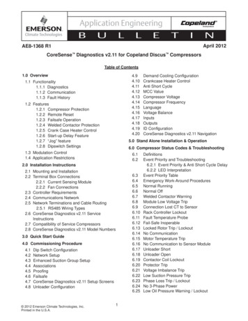
Application EngineeringApplication EngineeringBAE8-1328 R1BU UL LL E L T EICOPELAND SCROLL DIGITAL COMPRESSOR CONTROLLERIntroductionThe Digital Compressor Controller (543-0024-00)is the electronics interface between the CopelandScroll Digital Compressor and the system controller.The Digital Compressor Controller is designedonly for single and three phase Copeland ScrollDigital compressors (reference Copeland AE211319 for details on the Digital Compressor). Thesystem controller supplied by the OEM measurestemperature, pressure or humidity to calculate theneeded compressor capacity and communicatesthat capacity to the Digital Compressor Controllervia an analog signal. The compressor contactor coil is controlledbased on the capacity demand from the systemcontroller and the presence of any compressortrip or lock out conditions.INOctober, 2005preventing the compressor from restarting. For systems that need an accurate suctionpressure reading, the Digital CompressorController is able to smooth out the pressureswings associated with loading and unloadingthe compressor. A pressure transducer input is“filtered” by using the unloader control algorithmto output a smooth suction pressure signal. For systems that include a compressor vaporinjection solenoid valve, the compressorcontroller energizes this valve whenever thecompressor is running.The Digital Compressor Controller providescontrol, protection and diagnostics for the DigitalCompressor system. The Digital Compressor Controller “modulates”or cycles the unloader solenoid in an on/offpattern according to the capacity demand signalfrom the system controller.TNAE8-1328 R1Width: 2.0”(51 mm)SpecificationsHeight:4.0”(102 mm) The compressor is protected against highdischarge temperature by a discharge temperaturethermistor. If the maximum temperature limit isexceeded, the Digital Compressor Controllerwill protect the compressor by turning it off.Depth: 6.0” (153 mm)Operating Temperature: -40 F to 150 F(-40 C to 65 C)Storage Temperature:-60 F* to 175 F(-49 C* to 80 C)Supply Voltage:19-28VAC, 48-62HzSupply Power:2 VA maximumUL Requirements:For power supply:use only with Class 2circuits, File #SA8958Enclosure ProtectionIP20, NEMA1 Seven ALERT codes are displayed indicatingan abnormal system or compressor condition.Depending on the severity of the code, theDigital Compressor Controller will shut down thecompressor or run the compressor in a limitedcapacity.*MIL-STD-810F, Method 502.4, 4.5.2 After each compressor shut down event, a twominute anti-short cycle delay timer is active1 2005, 2004 Copeland Corporation.Printed in the U.S.A.
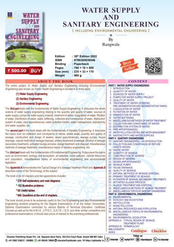
Application EngineeringBULLEAE8-1328 R1TINInstallationFour #10 self tapping sheet metal screws, atleast ½” length, are required for installation. Themaximum mounting screw torque is 20 in.lbs.Locate the Digital Compressor Controller inside theelectrical enclosure near the compressor contactor(wire routing for compressor power wiring will beeasier in this position). The maximum wire terminalscrew torque is 7 in. lbs. The Digital CompressorController will operate in any mounting orientationwhere the green POWER LED is at the top. Mountthe Digital Compressor Controller so all LEDs arevisible from a comfortable viewing position.A service panel label (Form 2003CC-80) describingthe terminals and ALERT flash codes is includedwith each Digital Compressor Controller. This labelshould be in a visible location for the technicianwhen he is troubleshooting the system.Digital Compressor Controller TerminalsSee Figure 1 and 2 for wiring diagrams.Low Voltage Terminals24VACModule Power24COM Module CommonC1Demand Input –C2Demand Input P1Pressure CommonP2Pressure InputP3Pressure Power 5VDCP4Pressure ShieldP5Pressure Output –P6Pressure Output T1Discharge Temp SensorT2Discharge Temp SensorCompressor WiringThe Digital Compressor Controller sensescompressor motor current for diagnostics andprotection. The compressor motor leads must berun through the holes in the plastic housing for acurrent transformer to sense motor current.Single Phase Compressors: the scroll compressor’srun (R), common (C) and start (S) wires must berouted through the holes in the Digital CompressorController module marked “R,” “C” and “S.” The runcapacitor may be located on either side of the DigitalCompressor Controller module.High Voltage TerminalsA1Alarm Relay OutA2Alarm Relay OutM1ContactorM2ContactorL1Control Voltage LL2Control Voltage NU1Unloader SolenoidU2Unloader SolenoidV1Vapor Injection SolenoidV2Vapor Injection SolenoidThree Phase Compressors: the scroll compressor’sT1, T2 and T3 wires must be routed through theholes in the Digital Compressor Controller modulemarked “T1,” “T2” and “T3.” The Digital CompressorController module is phase insensitive and will notdetect reverse phasing of the compressor.NOTE! Do not bundle low voltage wires withcompressor power or high voltage wires.NOTE! To avoid damaging the DigitalCompressor Controller do not connect wiresto terminals C3, C4, T3, T4, T5 or T6.NOTE! Attach cable ties through loops on sideof the housing for wire strain relief. 2005, 2004 Copeland Corporation.Printed in the U.S.A.2
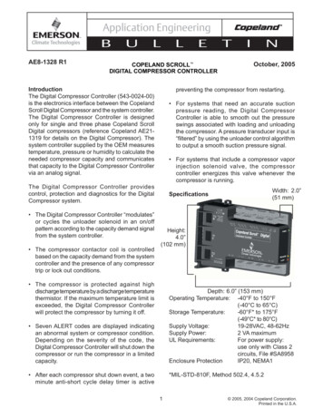
Application EngineeringBULLE(24VAC, 24COM) Digital Compressor ControllerPowerThe power supply for the Digital CompressorController is 19-28VAC, 48-62Hz. The maximumload is 2 VA. The 24VAC phasing for the DigitalCompressor Controller must match the systemcontroller to avoid a transformer short circuitcondition because the two controllers have theircommons connected together.AE8-1328 R1TINcorresponds to the range of the pressure transducerconnected to the System Pressure Input terminals.This output is capable of sourcing a maximum of10mA.(T1, T2) Discharge Temperature InputThe Discharge Temperature Input is a thermistorinput. There is no polarity requirement for thethermistor. For thermistor signal wiring, short wireruns are recommended. The cut out temperature is268 F (131 C) and the cut in or reset temperatureis 250 F (121 C). See Table 1 for thermistortemperature/resistance values.(C1, C2) System Controller DemandController Demand is an analog input signal fromthe system controller to the Compressor Controller,proportional to the capacity required from thecompressor. Controller Demand is a 1-5VDC inputwhere 1.0VDC is 0% capacity and 5.0VDC is 100%capacity. When the signal falls below 10% capacity(1.44VDC) the Digital Compressor Controller willshut down the compressor. When the signal risesabove 10% capacity (1.44VDC) and the anti-shortcycle timer has timed out, the Digital CompressorController will start the compressor again. SeeFigure 3 for a graphical representation. Themaximum input voltage for C1, C2 is 5.3 VDC.(A1, A2) Alarm RelayThe Alarm Relay output is a normally open, drycontact relay output. The maximum operatingvoltage for this relay is 250VAC or 30VDC and themaximum load is 3 A. During an alarm condition,the relay contacts close until the alarm conditionceases or power is turned off.(M1, M2) Compressor ContactorThe compressor contactor output is a triac output.The maximum continuous contactor coil loadis 0.5A and the peak inrush current is 6A. Themaximum coil operating voltage is 250VAC. Thisoutput is incompatible with DC coil voltages. Thecompressor contactor is energized when thereare no ALERT conditions and the demand signalis greater than 1.44VDC.(P1, P2, P3, P4) System Pressure InputIf a pressure transducer is used with the CompressorController, the System Pressure Input is ameasurement of the system suction pressure. Forpressure transducer signal wiring, short wire runsand shielded wiring are recommended. For bestsignal resolution, the smallest acceptable pressuretransducer range for the refrigerant should beused. The Digital Compressor Controller provides aprecision source 5VDC for the pressure transducerto accurately measure the pressure. This 5VDCsource is capable of sourcing a maximum of10mA(L1, L2) Control PowerNOTE! Control Power supplied to DigitalCompressor Controller must be the samevoltage as the compressor contactor coil,unloader solenoid and vapor injectionsolenoid.(P5, P6) System Pressure OutputIf a pressure transducer is connected to theSystem Pressure Input terminals, the SystemPressure Output provides an analog output of thefiltered suction pressure. The Digital CompressorController “filters” this suction pressure by usingthe unloader capacity algorithm to smooth thepressure fluctuations measured by the suctionpressure transducer. The output of 0.5 – 4.5VDCThe Control Power requirement is a single phase,19-250VAC, 48-62Hz source. The control powermust be isolated with a transformer fromthe mains power supply. The maximum loadon the control power circuit is 1.5A based on amotor contactor, unloader solenoid and vaporinjection solenoid connected to the CompressorController.3 2005, 2004 Copeland Corporation.Printed in the U.S.A.
Application EngineeringBULLE(U1, U2) Unloader SolenoidThe Unloader Solenoid output is a triac output.The maximum continuous solenoid load is 0.5Aand the peak inrush current is 6A. The maximumsolenoid operating voltage is 250VAC. This outputis incompatible with DC solenoid voltages. Theunloader solenoid is energized in an on/off patternto deliver the capacity requested by the demandsignal.TINDigital Compressor Controller LEDsPOWER LED (green) – indicates voltage is presentat the 24VAC power terminals. When the anti-shortcycle timer is active, the green LED will flash.(V1, V2) Vapor Injection SolenoidThe Vapor Injection Solenoid output is a triacoutput. The maximum continuous solenoid loadis 0.5A. The maximum solenoid operating voltageis 250VAC and the peak inrush current is 6A. Thisoutput is incompatible with DC solenoid voltages.The vapor injection solenoid is energized wheneverthe compressor contactor is energized.UNLOADER LED (yellow) – indicates the unloadersolenoid status. This LED is on when the unloadersolenoid is energized.Compressor Start And Shut DownThe Digital Compressor Controller always unloadsthe compressor for 0.1 seconds at each startup.After this brief unloading period, the unloadersolenoid will be deenergized and the compressorwill run loaded according to the level of the Demandinput signal. Each time the compressor shutsdown, the Digital Compressor Controller will run thecompressor unloaded for 0.5 seconds. Energizingthe unloader solenoid for this period of time willallow the discharge and suction pressures toequalize, minimizing scroll reverse rotation.ALERT LED (red) – communicates an abnormalsystem condition through a unique flash code.The ALERT LED will flash a number of timesconsecutively, pause and then repeat the process.The number of consecutive flashes, defined as theFlash Code, correlates to a particular abnormalcondition.Flash Code TroubleshootingWhile each ALERT code is active, the alarm relaycontacts (A1 and A2) are closed. The ALERT codewill remain active and the alarm relay contactsclosed until the reset conditions have been metor 24VAC power has been cycled off and on. AllFlash Codes except Code 6 and 8 result in thecompressor contactor, unloader solenoid andvapor injection solenoid being deenergized.Compressor RunningThe loaded/unloaded cycle always equals 20seconds. The loaded sequence always precedesthe unloaded sequence. Capacity modulation isachieved by energizing and de-energizing thesolenoid valve. When the solenoid valve is deenergized, the compressor capacity is 100%. Whenthe solenoid valve is energized, the compressorcapacity is zero. Therefore, the capacity achievedis the time average capacity, which is a variablefrom 10 – 100%. Example: If the solenoid is deenergized (loaded) for 16-seconds, then energized(unloaded) for 4-seconds, the resulting capacitywill be 80%. 2005, 2004 Copeland Corporation.Printed in the U.S.A.AE8-1328 R1All LEDs flashing at the same rate indicates 24VACsupply is too low for operation. All LEDs on solidat the same time indicates Digital CompressorController failure.Whenever power is cycled off and on, the currentFlash Code and all internal counters are reset.4
Application EngineeringBULLEFlash Code 1 - Reserved for future useAE8-1328 R1TINoutput will reset. The Digital Compressor Controllerwill attempt to restart compressor as long as thesystem controller demand is above 1.44VDC.There is no lockout feature for this ALERT.Flash Code 2 - High Discharge TemperatureThe discharge temperature thermistor hasmeasured a temperature above 268 F (130 C) orthe thermistor is short circuited (jumpered out).Flash Code 4 - Locked RotorA locked rotor condition in the compressor issensed by the Digital Compressor Controller onfour consecutive start ups.The Digital Compressor Controller will deenergizethe compressor contactor, unloader solenoid andvapor injection solenoid. The alarm relay contactswill close.The Digital Compressor Controller will deenergizethe compressor contactor, unloader solenoid andvapor injection solenoid. The alarm relay contactswill close.The compressor will be allowed to restart after a 30minute delay and after the thermistor temperatureis below 250 F (120 C). The flash code and alarmrelay contacts will be reset after the compressorhas run for 60 uninterrupted minutes without anyother ALERTs.This code results in a lockout and can only be resetby cycling the 24VAC power off and on.Flash Code 5 - Demand Signal LossThe demand signal input has dropped below0.5VDC. The demand input signal wire may bedisconnected or the system controller providingthe signal may not be powered.If five high discharge temperature ALERTs haveoccurred within four hours, the Digital CompressorController will lock out the compressor. The lockoutcan only be reset by cycling the 24VAC power offand on.The Digital Compressor Controller will deenergizethe compressor contactor, unloader solenoid andvapor injection solenoid. The alarm relay contactswill close.Flash Code 3 - Compressor Protector TripThe demand signal from the system controller isgreater than 1.44VDC and there is no compressorcurrent detected. This could be due to thecompressor’s internal overload protector beingopen, fuse or breaker open, power disconnectedto compressor contactor, compressor power wiringnot run through Digital Compressor Controllercurrent transformer port or a compressor contactorfailure.Once the system controller demand signal inputhas risen above 0.5VDC, the ALERT code andalarm relay output will reset. If the demand signalis above 1.44VDC and the anti-short cycle timerhas timed out, the compressor will restart.Flash Code 6 - Discharge Thermistor FaultThe Digital Compressor Controller is not receivinga signal from the discharge temperature thermistor.The thermistor may be missing, disconnected ora wire is broken.The Digital Compressor Controller will deenergizethe compressor contactor, unloader solenoid andvapor injection solenoid. The alarm relay contactswill close.The Digital Compressor Controller will wait forthe two minute anti-short cycle timer to time outand if the system controller demand signal is stillgreater than 1.44VDC, energize the compressorcontactor again. If compressor current is detectedon the restart, the ALERT code and alarm relayThe alarm relay contacts will close and the DigitalCompressor Controller will not increase thecapacity of the compressor beyond 50% loading.This ALERT code and alarm relay output are resetby reconnecting the thermistor.5 2005, 2004 Copeland Corporation.Printed in the U.S.A.
Application EngineeringBULLEFlash Code 7 - Unloader Solenoid FaultReserved for future useTINapplied between the High Voltage Controland High Voltage Outputs is 2500VAC. Thenormal leakage current should be less than200 microamps.Flash Code 8 - Compressor Contactor FaultCompressor current is detected when the systemcontroller demand signal is below 1.44VDC. Thecompressor contactor may have welded contactsor the contacts may be mechanically jammed. Thecompressor will continue to run in this conditionsince the Digital Compressor Controller cannotopen the compressor contactor.Testing The Installed Digital CompressorControllerOnce installed, the Digital Compressor Controllercan be tested to verify it is working properly. Ineach test, 24VAC must be supplied to 24VAC and24COM. For the output test, 24-250VAC must besupplied to L1 and L2.The Digital Compressor Controller will energize thecompressor contactor and vapor injection solenoid.The alarm relay contacts will close. The unloadersolenoid will remain energized causing thecompressor to run unloaded as long as the systemcontroller demand signal is less than 1.44VDC.If the system controller demand is greater than1.44VDC, the unloader solenoid will deenergizecausing the compressor to run loaded.Input TestsThermistor Input – disconnect the dischargetemperature sensor wires from terminals T1 andT2. If functioning normally, the Digital CompressorController should display a Code 6 unless aprevious ALERT code was present.Demand Input – disconnect the System ControllerDemand signal wires from C1 and C2. If functioningnormally, the Digital Compressor Controller shoulddisplay a Code 5 unless a previous ALERT codewas present.The ALERT code and alarm relay output are resetwhen current is no longer detected while systemcontroller demand signal is below 1.44VDC.Flash Code 9 - Low 24VAC SupplySupply voltage to the Digital Compressor Controllerhas dropped below 18.5VAC.Output TestsContactor Output – while the Digital CompressorController is powered off (no supply voltage to24VAC and 24COM), disconnect the SystemController Demand signal wire from C1 and C2.Add a jumper wire from P3 to C2 and a secondjumper wire from P1 to C1. Reapply power to24VAC and 24COM. If functioning normally, avoltmeter should read the same voltage across M1and M2 as is measured across L1 and L2, unlessan ALERT code is present.The Digital Compressor Controller will deenergizethe compressor contactor, unloader solenoid andvapor injection solenoid. The alarm relay contactsmay close if the voltage is high enough for thealarm relay to pull in.The ALERT code and alarm relay output are resetwhen the supply voltage to the Digital CompressorController rises above 19.5VAC.Unloader Output – while Digital CompressorController is modulating the unloader solenoid, avoltmeter should read the same voltage across U1and U2 as is measured across L1 and L2 wheneverthe yellow “Unloader “LED is lit.OEM TestingThe Digital Compressor Controller can remainin circuit during factory hi-pot testing. Themaximum hi-pot test voltage that should beapplied between ground and the 24VAC LowVoltage Inputs and Outputs is 600VAC. Themaximum hi-pot test voltage that should be 2005, 2004 Copeland Corporation.Printed in the U.S.A.AE8-1328 R16
Application EngineeringBULLEAE8-1328 R1TINFigure 1Compressor Controller Wiring Diagram7 2005, 2004 Copeland Corporation.Printed in the U.S.A.
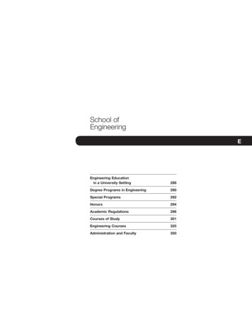
Application EngineeringBULLEAE8-1328 R1TINFigure 2Alternate Compressor Controller Wiring Diagram 2005, 2004 Copeland Corporation.Printed in the U.S.A.8
Application EngineeringBULLEAE8-1328 R1TINFigure 3Demand Signal Vs. Modulation Graph9 2005, 2004 Copeland Corporation.Printed in the U.S.A.
Application EngineeringBULLAE8-1328 R1ETINTable 1Thermistor Temperature/Resistance ValuesDeg C-40Deg F-40Resistance (kOhms)Deg CDeg FResistance 3560.83 2005, 2004 Copeland Corporation.Printed in the U.S.A.10Revised 9/05Copeland is a registered trademark and Copeland Scroll is a trademark ofCopeland Corporation. Emerson Climate Technologies and the Emerson ClimateTechnologies are trademarks and service marks of Emerson Electric Co.
AE8-1328 R1 COPELAND SCROLL October, 2005 DIGITAL COMPRESSOR CONTROLLER Introduction The Digital Compressor Controller (543-0024-00) is the electronics interface between the Copeland Scroll Digital Compressor and the system controller. The Digital Compressor Controller is designed only for single and three phase Copeland Scroll