Transcription
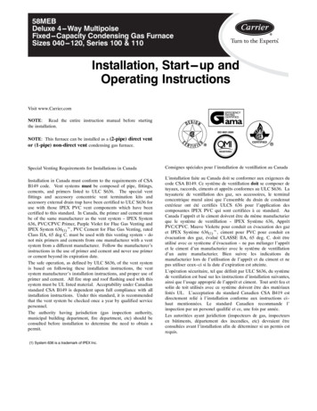
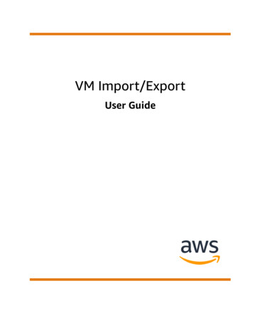
Operating instructionEC2-552 Condensing Unit ControllerGeneral information:The EC2-552 has been designed to control single compressor or tandem compressorcondensing units with a Copeland Scroll DigitalTM compressor and variable fan speedcontrol. The purpose of the controller is to maintain suction pressure at a pre-definedlevel by modulating compressors and to keep condensing pressure to a minimum byvarying fan motor speed.The PT5 pressure transmitter (1) senses suction pressure. The Digital ScrollCompressor (6) operates as the base load compressor. Capacity modulation isachieved by temporarily unloading the compressors scroll sets with the Pulse WidthModulated (PWM) signal (11) which controls the compressor unloading valve (12).In tandem compressor condensing units, the single stage compressor (7) will only beturned on when demand exceeds the refrigeration capacity of the Digital ScrollCompressor. The discharge temperature thermistor of the Digital Scroll Compressorshould be connected to the Disch. Temp. input (5) of the controller and the volt-freedigital inputs (3) and (4) should be connected to the serial alarm loops of bothcompressors for feedback of compressor tripping.Scroll compressor1Installation: The EC2-552 can be mounted in panels with a71 x 29 mm cutout. See dimensional drawing belowfor space requirements including rear connectors. Push controller into panel cutout. (1) Make sure that mounting clamps are flush withoutside of controller housing Insert allen key into front panel holes and turnclockwise. Mounting clamp will turn and graduallymove towards panel (2) Turn allen key until mounting clamp barely touchespanel. Then move other mounting clamp to the sameposition (3) Tighten both sides very carefully until controller issecured. Do not over tighten as mounting clampswill break easily.Electrical installation: Refer to the electrical wiring diagram (right) for electrical connections. A copy ofthis diagram is labelled on the controller. Use connection wires/cables suitable for 90 C operation (EN 60730-1) EC2 analog inputs are for dedicated sensors only and should not be connected toany other devices. Volt free digital inputs should only be connected to serial controlloops or relays with gold contacts. They should not be connected to any otherdevicesP10Digital scrollcompressorNote:Keep controller and sensorwiring well separated frommains wiring. Minimumrecommendeddistance30 mm.P0100%10%0%P0setpointpressureTwo control loops with the same suction pressure setpoint P0 modulate thecompressors. The dead band control loop with dead band P1 switches the single stagecompressor on or off, whereas a PI control loop modulates the Digital Scroll baseload compressor between approximately 10% and 100% capacity. Being the baseload compressor, the Digital Scroll Compressor will never be switched off while thesingle stage compressor remains on.The PT5 pressure transmitter (2) senses condensing pressure and feeds the signalinto a control loop which generates a 0 10V output signal (10) to modulatecondenser fan motor speed by using the EMERSON FSP Fan Speed Power Module.The control algorithm for condensing pressure is generating a proportional transfercharacteristic: Use a class II category transformer for 24 VAC power supply (EN 60742). Do notground the 24 VAC lines. We recommend to use one transformer per EC2controller and to use separate transformers for 3rd party controllers, to avoidpossible interference or grounding problems in the power supply. Connecting anyEC2 inputs to mains voltage will permanently damage the EC2.P1100%0%P0pressureP0 condensing pressure setpoint for the fan.P1 proportional pressure band within the fan speed is controlled proportionalSafety instructions: Read operating instructions thoroughly. Failure to comply can result in devicefailure, system damage or personal injury. According to EN 13313 it is intended for use by persons having theappropriate knowledge and skill. Do not exceed the specified maximum ratings for pressure, temperature,voltage and current. Before installation or service disconnect all voltages from system and device. Do not operate system before all cable connections are completed. Entire electrical connections have to comply with local regulations. Disposal: Electrical and electronic waste must NOT be disposed of with othercommercial waste. Instead, it is the user responsibility to pass it to adesignated collection point for the safe recycling of Waste Electrical andElectronic Equipment (WEEE directive 2012/19/EU). For furtherinformation, contact your local environmental recycling center.Emerson Climate Technologies GmbHAm Borsigturm 31 I 13507 Berlin I GermanyEC2-552 display/IR remote control unit: (LEDs)The data to be shown on the display can be selected by the user. In case of an alarm,the alarm code is displayed alternately with the selected data. The user can inhibitthe alarm code. Press the SEL button to scroll through all possible displayable data. The displaywill show for one second the numerical identifier of the data and then the selecteddata. After two minutes the display will return to the by parameter /1 selected data.Display indicates suction side - C1Ethernet activity LEDIR LED(only active when service pin is pressed)Display indicates condenser side - C2Display indicates pressure in barAlarm conditionCompressor 2 onCompressor 1 onFan onwww.emersonclimate.euDate: 02.05.2017EC2-552 OI ML R08 864923.docx
Operating instructionEC2-552 Condensing Unit ControllerSe t-up a nd pa ra me te r mo d i fi ca tio n usi ng the ke y pa d:For convenience, an infrared receiver for the optional IR remote control unit isbuild-in, enabling quick and easy modification of the system parameters when acomputer interface is not available.Alternatively, the parameters can be accessed via the 4-button keypad. Theconfiguration parameters are protected by a numerical password. The defaultpassword is “12”. To select the parameter configuration: Press the PRG button for more than 5 seconds; a flashing 0 is displayed Pressoruntil 12 is displayed; (password)Press SEL to confirm passwordThe first modifiable parameter code is displayed (/1).To modify parameters see "Parameter Modification" below.Parameter modification: procedure Pressorto show the code of the parameter that must be changed; Press SEL to display the selected parameter value; Pressorto increase or decrease the value; Press SEL to temporarily confirm the new value and display its code; Repeat the procedure from the beginning "pressor to show."To exit and save the new settings:Press PRG to confirm the new values and exit the parameters modificationprocedure.To exit without modifying any parameter: Do not press any button for at least 60 seconds (TIME OUT). Press “ESC” on IR remote control.Temporary Display of Data:It is possible to temporarily display the values of the different sensors. This is a usefulfeature when initially setting-up the system without the aid of the WebPages. Pressthe SEL sequentially. The value displayed on the screen corresponds to the numbercorresponding to the /1 parameter. Action only valid when parameter H2 3Load Default Parameters:The default parameter settings can be reloaded into the controller memory by usingthe special function described below.Special Functions:The Special Functions can be activated by: Pressandtogether for more than 5 seconds. A flashing 0 is displayed. Pressoruntil the password is displayed (default 12). If password waschanged, select the new password. Press SEL to confirm password. A 0 is displayed and the Special Function modeis activated. Pressorto select the function. The number of special functions is dynamicand controller dependent. See list below. Press SEL to activate the function without leaving the special function mode. Press PRG to activate the function and leave the special function mode.Most of the Special Functions work in a toggle mode, the first call activates thefunction, and the second call deactivates the function.The indication of the function can only be displayed after exiting the special functionmode. 0: Display test function 1: Displays the current TCP/IP address 2: Set the controller TCP/IP address to the default value: 192.168.1.101 3: Resets all parameters to the factory default setting. The controller willindicate “oF” during the reset.The data to be shown on the display can be selected by the user. In case of an alarm,the alarm code is displayed alternately with the selected data. The user can inhibitthe alarm code. Press the SEL button to scroll through all possible displayable data.The display will show for one second the numerical identifier of the data and thenthe selected data. After two minutes the display will return to the by parameter /1selected data.Emerson Climate Technologies GmbHAm Borsigturm 31 I 13507 Berlin I GermanyIndications on The Display:Compressor Controller State Alarm in combination with alarm message and alarm LED Suction pressure or saturation temperature from suction pressure ParameterCondenser fan controller State Alarm in combination with alarm message and alarm LED Condensing pressure or saturation temperature from condensing pressure ParameterOther display Pressure: Pressure value in bar (g) Alarm: Alarm condition IR: IR communication enabledAlarm Codes:hP High pressure alarmController 1: suction pressure higher than the maximum limitController 2: condensing pressure higher than the maximum limitlP Low pressure alarmController 1: suction pressure lower than the minimum limitController 2: condensing pressure lower than the minimum limitd1 Discharge temperature alarmDigital scroll only: Discharge end temperature is too highEP Error pressureController 1: suction pressure sensor failureController 2: condensing pressure sensor failureFr Fast recovery alarmController 1: fast recovery from low suction pressureController 2: fast recovery from low condensing pressurehr High discharge pressure alarmController 1: high discharge pressure recoveryController 2: high discharge pressure recoveryrE Emergency runController 1: runs with c6 numbers of compressorsController 2: runs with c6 numbers of fansE1 Feedback alarm 1Controller 1: digital input associated with compressor 1 has changed into alarmstate (safety chain)Controller 2: digital input associated with fan(s) has changed into alarm state(safety chain)E2 Feedback alarm 2Controller 1: digital input associated with compressor 2 has changed into alarmstate (safety chain)n1 Service alarm 1Controller 1: compressor 1 operating time higher than run limit (A9)Controller 2: fan operating time higher than run limit (A9)n2 Service alarm 2Controller 1: compressor 2 operating time higher than run limit (A9)Er Data errorData send to the display is out of rangeMessages--- No data to displayThe display will show an “---” at node start up and when no data is send to thedisplay.In Reset to default values activatedThe display will show an “In” when the factory default configuration data set isinitialized.Id Wink request receivedThe display will show a flashing “Id” when the wink request was received. Theflashing “Id” will be shown on the display until the service button will bepressed, or a 3 min delay timer will expire or a second wink request is received.This function is action only when using SNMP protocolOF Node is offlineThe node is offline and no application is running. This is the result of a networkmanagement command and will happen for example during node installation.www.emersonclimate.euDate: 02.05.2017EC2-552 OI ML R08 864923.docx
Operating instructionEC2-552 Condensing Unit ControllerController 1 (Compressor controller):Min Max Unit/DISPLAY PARAMETERS/1Value to be shown on display070 compressors and fans states (controller 1 and 2)1 suction pressure (bar)2 saturation temperature from suction pressure ( C)3 condensing pressure (bar)4 saturation temperature from condensing pressure ( C)5 Digital Scroll capacity (%)6 fan speed (%)7 Digital Scroll discharge temperature ( C)PP0P3P8SET-POINT PARAMETERS - C1Pressure set-point (suction) forcompressor circuitPressure band (control band for P/PI,dead band for dead band control mode)Fast recovery from low pressureHigh discharge pressure recoverytt1(1)t2(1)t3(1)t4(1)t5TIME PARAMETERSTime delay before adding capacityTime delay before removing capacityCompressor minimum on timeCompressor minimum off timeMaximum compressor switchingAA2ALARM PARAMETERS - C1Minimum suction pressure alarmlimitMaximum suction pressure alarmlimitDelay time for minimum pressurealarm limitDelay time for maximum pressurealarm limitHigh discharge temperature cut-outcut-in cut-out – 10 CCompressor serial alarm delayCompressor run sec10sec1/hr33660Min Max UnitDef Individ.SENSOR PARAMETERS - C1Suction pressure sensor minimum-1.0 50bar-0.8valueSuction pressure sensor maximum-1.0 50bar7.0valuePressure offset for suction pressure-1.0 1.0bar0.0Refrigerant type01340 no temperature conversion;1 R22,2 R134a, 3 R507, 4 R404A, 5 R407C,6 R407A 7 R407F, 8 R410A, 9 R448A, 10 R449A,11 R450A, 12 R513A, 13 R452AController 2 (Fan controller)PP0P1MinSET-POINT PARAMETERS - C2Pressure set-point (condensing) for -1.0fan circuitPressure band (control band for0.0P/PI, dead band for dead bandcontrol mode)AA2ALARM PARAMETERS - C2Minimum condensing pressurealarm limitA3 Maximum condensing pressurealarm limitA4(1) Delay time for minimum pressurealarm limitA5(1) Delay time for maximum pressurealarm limitA9(2) Fan run 50bar1.0-1.050bar6.009910sec009910sec0100140 C13000999910sec10 000hr003-0c611flagflag11FF2F3MODULATING PARAMETERS - C2Minimum output value0Maximum output value0rr0SENSOR PARAMETERS - C2Condensing pressure sensorminimum valueCondensing pressure sensormaximum valuePressure offset for condensingpressureSTEP ENABLE PARAMETERS - C1Reset operating time00 do nothing1 reset operating time compressor 12 reset operating time compressor 23 reset operating time all compressorsEnable/disable compressor 10Enable/disable compressor 20APPLICATION PARAMETERS - C1Number of compressors122Compressor 1 control mode0220 compressor 1 in standard control loop1 compressor 1 act as base load compressor2 compressor 1 is a digital scroll compressor & base loadCompressor switch logic01flag00 FILO logic (First In, Last Out)Capacity demand: Adds first compressor out of available compressors.( compressors where min off time (t4) is fulfilled)Capacity excess: Removes last compressor out of available compressors.( compressors where min on time (t3) is fulfilled)1 Rotation enabledCapacity demand: Adds compressor with lowest runtime out of availablecompressors. ( where min off time (t4) is fulfilled)Capacity excess: Removes compressor with highest runtimes out ofavailable compressors. ( where min on time (t3) is fulfilled)Number of compressors to switch on 020in case of sensor failureMODULATING PARAMETERS - C1Minimum output value10Maximum output value10PWM rate (Digital scroll)10Emerson Climate Technologies GmbHAm Borsigturm 31 I 13507 Berlin I Germany10010020%%secuu0u1cc2r1r2STEP ENABLE PARAMETERS - C2Reset operating time00 do nothing1 reset operating time fan 1Enable/disable fan 10APPLICATION PARAMETERS - C2Fan controller operation00 disabled1 enabledFan behaviour on in case of sensor0failure0 Analog output 0% (0 V)1 Analog output 100% (10 V)Individ.HH2OTHER PARAMETERSKeyboard and IR remote control0330 all disabled(Caution, access to controller only via network possible)1 Keyboard enabled2 IR remote control enabled3 Keyboard and IR remote control enabledH3 IR remote control access code01990H5 Password019912(1)Shown value x 10 Time in seconds. Ex. a value of 2 means 20 seconds.(2)Shown value x 10 000 Time in hours. Ex. a value of 2 means 20.000 hours.2010020www.emersonclimate.euDate: 02.05.2017EC2-552 OI ML R08 864923.docx
Operating instructionEC2-552 Condensing Unit ControllerVisualizing Data: WebPagesA TCP/IP Controller-Readme file is available on the www.emersonclimate.euwebsite to provide detailed information about TCP/IP Ethernet connectivity. Pleaserefer to this file if you need information beyond the contents of this instruction sheet.The EC2-552 has a TCP/IP Ethernet communication interface enabling the controllerto be directly connected to a PC or network via the standard Ethernet port. The EC2552 controller has embedded WebPages to enable the user to easily visualise theparameter lists using real text labels.No special software or hardware is required.Connect the EC2-552 using the optional ECX-N60 cable assembly to a network orhub that enables the controller to receive a dynamic TCP/IP address. If a DHCPserver is not available, the controller can be connected to a computer using acrossover cable plugged directly into the Ethernet port. In this case, the TCP/IPaddress of the computer must be manually modified to be compatible with the defaultaddress of the controller. Refer to the TCP/IP Controller-Readme file for moredetails.Open the Internet browser program on the computer and enter the default TCP/IPaddress of the controller into the address line of the Internet browser: 192.168.1.101or the dynamic address from the DHCP server. The default communication port is1030. Refer to the TCP/IP Controller-Readme file if a specific port is required.After a few moments, the default monitoring page should be displayed. If the browserdoes not open the default page or display active data, the user should check theInternet browser “Option” configuration. Refer to the TCP/IP Controller-Readmefile.Technical Data:Power supplyPower consumptionCommunicationPlug-in connector sizeTemperaturestorageoperatingHumidityProtection classPressure transmitter inputsDigital InputsVariable fan speed outputTriac outputOutput relays24 VAC 10%; 50/60 Hz; Class II20 VA max.TCP/IP Ethernet 10MBit/sRemovable screw terminalswire size 0.14 1.5 mm2-20 65 C0 60 C0 80% rh. non condensingIP65 (front protection with gasket)24 VDC, 4 20 mAVolt free contacts 5V/0,1 mA0 10 V, 3 mA max24 VAC 0,1 1 ASPDT contacts, AgCdOInductive (AC15) 250 V/2 AResistive (AC1) 250 V/8 A; 12 A total returncurrentMarkingIn addition, for those customers wishing to connect the controllers into a largersystem, it is also possible to trap network variables using the SNMP protocol. Referto the User Manual for further details.The Monitoring and Alarm WebPages are read only and therefore it is not necessaryto enter a username or password. A username and password will be requested uponthe initial request to any of the other WebPages. The factory default settings are:Username: EmersonIDPassword: 12The default settings may be modified in the Display configuration page.Press the tabs at the top of the Monitoring page with a left click of the mouse buttonto enter the respective Webpage.The parameters will be visualised in real text together with the program code asdefined in the parameter list below.After the parameters have been modified, the complete list of settings can be savedto the memory of the computer and used later to upload into another controller. Thiscan save a considerable amount of time when using multiple controllers and over aperiod of time, a library can be created containing the parameter lists for equipmentfor different applications.It is also possible to display live graphical data from the controller. In addition, apermanent 30 days log file containing the control temperature at 15 minutes intervalsis stored in the non-volatile memory to be later transferred using FTP to the computer.The log file can be imported into a standard spreadsheet program such as Excel. Referto the TCP/IP Controller-Readme file for a complete description of the featuresavailable for the TCP/IP series of controllers.Emerson Climate Technologies GmbHAm Borsigturm 31 I 13507 Berlin I Germanywww.emersonclimate.euDate: 02.05.2017EC2-552 OI ML R08 864923.docx
BetriebsanleitungEC2-552 Regler für VerflüssigungssätzeBeschreibung:Der EC2-552 ist ein Regler für Verflüssigungssätze mit einem Digital Scroll vonCopeland, optional einem zweiten Scroll und drehzahlgeregelten Lüftern. Auf derSaugseite ist das Ziel der Regelung, durch Variation der Verdichterleistung denSaugdruck auf dem Sollwert zu halten, auf der Verflüssigungsseite, durchVeränderung der Lüfterleistung, den Verflüssigungsdruck über einem spezifiziertenWert zu halten.Der Saugdruck wird von einem Drucktransmitter PT5 (1) gemessen. Der DigitalScroll (6) arbeitet als Grundlastverdichter. Die Leistungsregelung wird durch einpulsbreitenmoduliertes Signal (11) erreicht, das auf die Anlaufentlastung desVerdichters (12) wirkt. In Tandem Verflüssigern wird der einstufige Verdichter (7)nur eingeschaltet, wenn der Leistungsbedarf die Leistung des Digital Scrollübersteigt. Der Temperaturfühler des Digital Scroll sollte an den entsprechendenTemperatureingang (5) des Reglers angeschlossen werden. An die spannungsfreienEingänge (3) und (4) werden die Sicherheitsketten der Verdichter angeschlossen.Scroll Verdichter1P10E l e ktr i sc he r Ansc hl uss: Die Anschlussklemmen sind auf dem Regler bezeichnet, siehe rechts. Die Anschlussdrähte/-kabel müssen für Betrieb bis 90 C zugelassen sein (EN60730-1). Die Analogeingänge des EC2 sind nur zum Anschluss der bezeichneten Sensorenzugelassen. Die spannungsfreien Digitaleingänge dürfen nur an Sicherheitskettenoder Relais mit Goldkontakten angeschlossen werden. Der Anschluss einesEinganges an die Netzspannung zerstört den EC2! Anschluss andererKomponenten ist nicht zulässig.P0100%Digital scrollVerdichterEinbau: EC2-552 wird auf Frontplatten mit einemAusschnitt von 71 x 29 mm montiert; sieheAbmessungen unten für Platzbedarf inkl. Stecker. Regler vorsichtig mit eingefahrenen Halterungen inden Frontplattenausschnitt einschieben (1). Beiliegenden Imbusschlüssel in die Löcher auf derFrontseite einstecken und im Uhrzeigersinn drehen.Die Halterungen treten aus dem Gehäuse hervor undbewegen sich in Richtung Frontplatte (2). Imbusschraube solange weiterdrehen, bis dieHalterung die Frontplatte leicht berührt, dann zweiteHalterung in dieselbe Position bringen (3). Beide Seiten gleichmäßig und vorsichtig anziehen,bis der Regler stabil sitzt. Achtung - nicht zu festanziehen, die Halterungen können sonst zspannungsollteningetrennten Kabelschächtenverlegt werden. Mindestabstand: 30 mm.10%0%P0SollwertDruckZwei Regelkreise mit demselben Sollwert P0 steuern die Verdichter. DerNeutralzonen-Regelkreis mit der Neutralzone P1 schaltet den einstufigen Verdichterein oder aus, während ein PI-Regelkreis den Digital Scroll Grundlastverdichterzwischen 10% und 100% moduliert. Da der Digital Scroll als Grundlastverdichterarbeitet, wird er nie ausgeschaltet solange der einstufige Verdichter läuft.Der Verflüssigungsdruck wird vom Drucktransmitter PT5 (2) gemessen und in eineProportionalregelung mit dem Proportionalband P1 und dem Sollwert P0 eingespeist.Die Regelung erzeugt ein analoges 0.10 V Signal mit dem über das LeistungsteilFSP (10) von EMERSON die Drehzahl der Lüfter (8) gesteuert werden.P1100%0%P0DruckSicherheitshinweise: Lesen Sie die Betriebsanleitung gründlich. Nichtbeachtung kann zumVersagen oder zur Zerstörung des Gerätes und zu Verletzungen führen. Der Einbau darf gemäß EN 13313 nur von Fachkräften vorgenommenwerden. Die angegebenen Grenzwerte für Druck, Temperatur, Strom und Spannungnicht überschreiten. Vor Installation oder Wartung sind die Anlage und das Bauteil spannungsfreizu schalten. Das Ventil nicht betreiben, wenn der Kompressor nicht läuft. Für den gesamten elektrischen Anschluss sind die länderspezifischenVorschriften einzuhalten. Entsorgung: Elektro- und Elektronik-Altgeräte dürfen nicht mit anderenGewerbemüll entsorgt werden. Stattdessen ist es in der VerantwortungBenutzer es zu einem Sammelpunkt für die sichere Entsorgung von Elektround Elektronik-Altgeräte (WEEE-Richtlinie 2012/19/EU) zu übergeben. Fürweitere Informationen kontaktieren Sie bitte Ihren örtlichen Recyclinghof.Emerson Climate Technologies GmbHAm Borsigturm 31 I 13507 Berlin I Germany Für die 24V Stromversorgung sind ausschließlich Transformatoren der Klasse IIzu verwenden (EN 60742). Die 24 V Leitungen dürfen nicht geerdet werden. Wirempfehlen die Verwendung jeweils separater EMERSON Transformatoren fürEC2 Regler und die Regler anderer Hersteller, weil unter Umständen über dieErdleitungen Kurzschlüsse entstehen können.EC2-552 Anzeige/Infrarotfernbedienung: (LEDs)Im Normalbetrieb ist auf der Anzeige einer von 8 Werten sichtbar. Dieser Wert wirdmit dem Parameter /1 ausgewählt (siehe Parametertabelle). Bei einem Alarm wirdder Alarmcode abwechselnd mit dem Messwert angezeigt. Die Anzeige desAlarmcodes kann unterdrückt werden.Die SEL-Taste drücken, um durch alle möglichen anzeigbaren Daten zu blättern. Eswird zuerst eine Sekunde lang die Parameterkennung, danach der Wert angezeigt.Nach zwei Minuten kehrt das Display zum Parameter / 1 ausgewählte Daten zurückAnzeige der Saugseite - C1Ethernet aktiviertIR LED(wenn der Service Pin gedrückt wurde).Anzeige der Verflüssigerseite - C2Druckanzeige in barAlarmVerdichter 2 einVerdichter 1 einLüfter einwww.emersonclimate.euDate: 02.05.2017EC2-552 OI ML R08 864923.docx
BetriebsanleitungEC2-552 Regler für VerflüssigungssätzeParametereinstellung mit der Tastatur:Falls kein PC angeschlossen ist, lassen sich die Parameter des Reglers mit derAnzeigeeinheit und der Infrarotfernbedienung EC2-IRD bequem verändern.Parameteränderungen sind auch mit der Gerätetastatur möglich. DieKonfigurationsparameter sind passwortgeschützt.Änderung der Konfigurationsparameter: PRG Taste länger als 5 Sek. gedrückt halten bis eine blinkende "0" erscheint oderTasten so oft drücken bis das Passwort (Standardwert 12) angezeigtwird mit SEL Taste bestätigen Der erste Konfigurationsparameter (/1) wird angezeigt.Parameter einstellen: oder Tasten so oft drücken, bis gewünschte Parameterkennung erscheint Mit SEL wird der aktuell eingestellte Wert angezeigt Mit oder wird dieser Wert vergrößert oder verkleinert Mit SEL wird der eingestellte Wert vorläufig behalten, aber noch nichtgespeichert. Die Parameterkennung wird wieder angezeigt. Zur Änderung weiterer Parameter wird diese Prozedur wiederholt; mit odernächste Parameterkennung auswählen.Parameter speichern und Konfigurationsmodus beenden: PRG Taste drückenParameter nicht speichern und Konfigurationsmodus ohne Parameteränderung beenden: Mindestens 60 Sekunden lang keine Taste drücken (Zeitsperre) „ESC“ auf Infrarotfernbedienung drückenTemporäre Anzeige der Daten:Mit "SEL" können die Messwerte aller Fühler nacheinander angezeigt werden. Diesist hilfreich, wenn das System ohne WebSeiten eingestellt werden soll. Hierbei istzuerst eine Sekunde lang die Parameterkennung, danach der Wert sichtbar. Diesfunktioniert nur, wenn der Parameter H2 3 ist.We r kse i nste l l ung la de n:Die Standardeinstellung des Reglers wird mit der Spezialfunktion 3 wiederhergestellt, siehe folgender Abschnitt.Spe z ia lf unkti o ne n:Diese Betriebsart wird folgendermaßen aufgerufen: undTasten zusammen länger als 5 Sek. gedrückt halten bis eine blinkende"0" erscheint oderTasten so oft drücken bis das Passwort (Standardwert 12) angezeigtwird. mit SEL Taste Passwort bestätigen. Es erscheint eine blinkende „0“ für die ersteSpezialfunktion Mitodereine andere Funktionskennung auswählen. Die Funktionskennungen sind je nach Regler unterschiedlich. Siehe Tabelle unten. Mit SEL wird die eingestellte Funktion aktiviert, die Betriebsart Spezialfunktionenbleibt aktiv. Mit PRG wird die gewählte Funktion aktiviert und die Betriebsart Spezialfunktionen verlassen.Die meisten Spezialfunktionen arbeiten im Togglemode, d.h. der erste Aufrufaktiviert, der zweite Aufruf deaktiviert die Funktion. Eine Anzeige derSpezialfunktion erfolgt erst nach dem Verlassen dieser Betriebsart. 0: Funktionstest der Anzeige 1: Aktuelle TCP/IP Adresse anzeigen 2: TCP/IP Adresse auf 192.168.1.101 (Werkseinstellung) setzen. DieseÄnderung ist nur temporär. Nach dem Abschalten wird die zuvor eingestellteAdresse wieder aktiviert. 3: Alle Parameter auf Werkseinstellung zurücksetzen. Anzeige während derRückstellung: "oF".Emerson Climate Technologies GmbHAm Borsigturm 31 I 13507 Berlin I GermanyIndi ka to r e n a uf de r Anze ig e :Regler für Verdichter Status Alarm in Verbindung mit Alarmcode und Alarm LED Saugdruck oder Sättigungstemperatur vom gemessenen SaugdruckRegler für Verflüssigerlüfter Status Alarm in Verbindung mit Alarmcode und Alarm LED Verflüssigungsdruck oder Sättigungstemperatur vom gemessenenVerflüssigungsdruckSonstige Anzeige Druckanzeige in bar (absolut) Alarm: Alarmcode IR: IR Fernbedienung aktivAlarmanzeigen:hP Grenzwert Druck MaxRegler 1: Saugdruck höher als Grenzwert max.Regler 2: Verflüssigungsdruck höher als Grenzwert max.lP Grenzwert Druck MinRegler 1: Saugdruck unter Grenzwert minRegler 2: Verflüssigungsdruck unter Grenzwert mind1 Temperaturalarm VerdichteraustrittNur für Digital Scroll: Austrittstemperatur zu hochEP FühlerbruchRegler 1: Saugdruck FühlerausfallRegler 2: Verflüssigungsdruck FühlerausfallFr Schnellrücklauf ND aktivRegler 1: Schnellrücklauf von zu niedrigem SaugdruckRegler 2: Schnellrücklauf von zu niedrigem Verflüssigungsdruckhr Schnellrücklauf HD aktivRegler 1: Schnellrücklauf von zu hohem VerflüssigungsdruckRegler 2: Schnellrücklauf von zu hohem VerflüssigungsdruckrE NotbetriebRegler 1: Bei Fühlerausfall läuft die in c6 spezifizierte Zahl von VerdichternRegler 2: Bei Fühlerausfall läuft die
Compressor. The discharge temperature thermistor of the Digital Scroll Compressor should be connected to the Disch. Temp. input (5) of the controller and the volt-free digital inputs (3) and (4) should be connected to the serial alarm loops of both compressors for feedback of compressor tripping. Scroll compressor Digital scroll compressor 10% .