Transcription
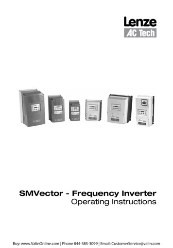
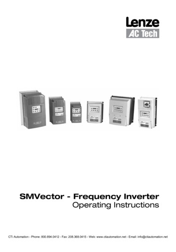
SMVector - Frequency InverterOperating InstructionsCTi Automation - Phone: 800.894.0412 - Fax: 208.368.0415 - Web: www.ctiautomation.net - Email: info@ctiautomation.net
Contents1Safety Information. 32Technical Data. 62.12.22.33Installation. 113.13.24Dimensions and Mounting.113.1.1NEMA 1 (IP31) Models 30HP (22kW).113.1.2NEMA 1 (IP31) Models 30HP (22kW).123.1.3NEMA 4X (IP65) Models.133.1.4NEMA 4X (IP65) Models with Disconnect Switch.14Electrical Installation.153.2.1Power Connections.153.2.1.1 Mains Connection to 120VAC Single-Phase Supply.153.2.1.2 Mains Connection to 240VAC Single-Phase Supply.163.2.1.3 Mains Connection to Three-Phase Supply.163.2.1.4 Motor Connection.163.2.1.5 Installation Recommendations for EMC Compliance.173.2.1.6 NEMA 4X (IP65) Input Terminal Block.173.2.1.7 Dynamic Brake Connections.183.2.2Fuses/Cable Cross-Sections.193.2.3Control Terminals.20Commissioning. 224.14.24.34.44.55Standards and Application Conditions.6SMV Type Number Designation.7Ratings.8Local Keypad & Display.22Drive Display and Modes of Operation.24Parameter Setting.25Electronic Programming Module (EPM).25Parameter Menu.264.5.1Basic Setup Parameters.264.5.2I/O Setup Parameters.304.5.3Advanced Setup Parameters.344.5.4PID Parameters.384.5.5Vector Parameters.404.5.6Network Parameters.424.5.7Diagnostic Parameters.434.5.7.1 Terminal & Protection Status Display.444.5.7.2 Keypad Status Display.444.5.8Onboard Communications Parameters 15-60HP (11-45kW).454.5.9Sequencer Parameters.464.5.9.1 Sequencer Flow Diagram Left.544.5.9.2 Sequencer Flow Diagram Right.554.5.9.3 Sequencer Status.56Troubleshooting and Diagnostics. 575.15.25.3Status/Warning Messages.57Drive Configuration Messages.58Fault Messages.58Appendix A. 61A.1Permissable Cable Lengths.61CTi Automation - Phone: 800.894.0412 - Fax: 208.368.0415 - Web: www.ctiautomation.net - Email: info@ctiautomation.netSV01M1
About These InstructionsThis documentation applies to the SMV frequency inverter and contains important technical data regarding theinstallation, operation, and commissioning of the inverter.These instructions are only valid for SMV frequency inverters with software revision 4.23 or higherFor version 4.23 software, the drive nameplate illustrated below would show “42” in the “F” location.Please read these instructions in their entirety before commissioning the drive.ABCDOUTPUT: 3 (3/PE)0 - 400/460 V2.4/2.1 A0.75 KW/1HP0 - 500 HZTYPE-4X INDOOR USE ONLYE FFor detailed informationrefer to instructionManual: SV01INPUT: 3 (3/PE)400/480 V2.9/2.5 A50-60 HZType:ESV751N 0 4TXBId-No: 00000000000000000000000000ESV751N0 4TXB000XX ## ##ABCDEFCertificationsTypeInput RatingsOutput RatingsHardware VersionSoftware VersionScope of deliveryImportant 1 SMV Inverterwith EPM installed (see Section 4.4) 1 Operating Instructions manualAfter receipt of the delivery, check immediately whether the items delivered matchthe accompanying papers. Lenze AC Tech does not accept any liability for deficienciesclaimed subsequently.Claim: visible transport damage immediately to the forwarder. visible deficiencies /incompleteness immediately to your Lenze AC Tech repRelated DocumentsThe documentation listed herein contains information relevant to the operation of the SMVector frequency inverter. To obtain the latestdocumentation, visit the Technical Library at Lenze website.Document #DescriptionCMVINS01SMVector Communications Module Installation InstructionCMVMB401SMVector ModBus RTU over RS485 Communications Reference GuideCMVLC401SMVector Lecom Communications Reference GuideCMVCAN01SMVector CANopen Communications Reference GuideCMVDVN01SMVector DeviceNet Communications Reference GuideCMVETH01SMVector EtherNet/IP Communications Reference GuideCMVPFB01SMVector PROFIBUS Communications Reference GuideALSV01SMVector Additional I/O Module Installation and Operation ManualDBV01SMVector Dynamic BrakingPTV01SMVector Potentiometer Install InstructionsRKV01SMVector ESVZXK1 Remote KeypadRKVU01SMVector ESVZXH0 Remote Keypad (for NEMA 1 15-60HP (11-45kW) Drives)Copyright 2006 Lenze AC Tech CorporationAll rights reserved. No part of this manual may be reproduced or transmitted in any form without written permission from Lenze AC TechCorporation. The information and technical data in this manual are subject to change without notice. Lenze AC Tech Corporation makes nowarranty of any kind with respect to this material, including, but not limited to, the implied warranties of its merchantability and fitness for agiven purpose. Lenze AC Tech Corporation assumes no responsibility for any errors that may appear in this manual.All information given in this documentation has been carefully selected and tested for compliance with the hardware and software described.Nevertheless, discrepancies cannot be ruled out. Lenze AC Tech does not accept any responsibility nor liability for damages that may occur.Any necessary corrections will be implemented in subsequent editions. This document is printed in the United States2SV01M
Safety Information1Safety InformationGeneralSome parts of Lenze AC Tech controllers can be electrically live and some surfaces can be hot. Non-authorized removalof the required cover, inappropriate use, and incorrect installation or operation creates the risk of severe injury topersonnel and/or damage to equipment.All operations concerning transport, installation, and commissioning as well as maintenance must be carried out byqualified, skilled personnel who are familiar with the installation, assembly, commissioning, and operation of variablefrequency drives and the application for which it is being used.InstallationEnsure proper handling and avoid excessive mechanical stress. Do not bend any components and do not change anyinsulation distances during transport, handling, installation or maintenance. Do not touch any electronic componentsor contacts. This drive contains electrostatically sensitive components, which can easily be damaged by inappropriatehandling. Static control precautions must be adhered to during installation, testing, servicing and repairing of this driveand associated options. Component damage may result if proper procedures are not followed.To ensure proper operation, do not install the drive where it is subjected to adverse environmental conditions such ascombustible, oily, or hazardous vapors; corrosive chemicals; excessive dust, moisture or vibration; direct sunlight orextreme temperatures.This drive has been tested by Underwriters Laboratory (UL) and is UL Listed in compliance with the UL508C SafetyStandard. This drive must be installed and configured in accordance with both national and international standards.Local codes and regulations take precedence over recommendations provided in this and other Lenze AC Techdocumentation.The SMVector drive is considered a component for integration into a machine or process. It is neither a machine nora device ready for use in accordance with European directives (reference machinery directive and electromagneticcompatibility directive). It is the responsibility of the end user to ensure that the machine meets the applicablestandards.Electrical ConnectionWhen working on live drive controllers, applicable national safety regulations must be observed. The electricalinstallation must be carried out according to the appropriate regulations (e.g. cable cross-sections, fuses, protectiveearth [PE] connection). While this document does make recommendations in regards to these items, national and localcodes must be adhered to.The documentation contains information about installation in compliance with EMC (shielding, grounding, filters andcables). These notes must also be observed for CE-marked controllers. The manufacturer of the system or machine isresponsible for compliance with the required limit values demanded by EMC legislation.ApplicationThe drive must not be used as a safety device for machines where there is a risk of personal injury or material damage.Emergency Stops, over-speed protection, acceleration and deceleration limits, etc must be made by other devices toensure operation under all conditions.The drive does feature many protection devices that work to protect the drive and the driven equipment by generatinga fault and shutting the drive and motor down. Mains power variances can also result in shutdown of the drive. Whenthe fault condition disappears or is cleared, the drive can be configured to automatically restart, it is the responsibilityof the user, OEM and/or integrator to ensure that the drive is configured for safe operation.CTi Automation - Phone: 800.894.0412 - Fax: 208.368.0415 - Web: www.ctiautomation.net - Email: info@ctiautomation.netSV01M3
Safety InformationExplosion Proof ApplicationsExplosion proof motors that are not rated for inverter use lose their certification when used for variable speed. Due tothe many areas of liability that may be encountered when dealing with these applications, the following statement ofpolicy applies:Lenze AC Tech Corporation inverter products are sold with no warranty of fitness for a particular purpose or warrantyof suitability for use with explosion proof motors. Lenze AC Tech Corporation accepts no responsibility for any direct,incidental or consequential loss, cost or damage that may arise through the use of AC inverter products in theseapplications. The purchaser expressly agrees to assume all risk of any loss, cost or damage that may arise from suchapplication.OperationSystems including controllers must be equipped with additional monitoring and protection devices according to thecorresponding standards (e.g. technical equipment, regulations for prevention of accidents, etc.). The controller may beadapted to your application as described in this documentation.DANGER! After the controller has been disconnected from the supply voltage, live components and power connectionmust not be touched immediately, since capacitors could be charged. Please observe the corresponding noteson the controller.Close all protective covers and doors prior to and during operation.Do not cycle input power to the controller more than once every two minutes.For SMVector models that are equipped with a Disconnect Switch (11th character in model number is L or M),the Disconnect Switch is intended as a motor service disconnect and does not provide branch circuit protectionto the inverter or motor. When servicing the motor, it is necessary to wait 3 minutes after turning this switchto the off position before working on motor power wiring as the inverter stores electrical power. To service theinverter, it is necessary to remove mains ahead of the drive and wait 3 minutes.Safety NotificationsAll safety information given in these Operating Instructions includes a visual icon, a bold signal word and adescription.Signal Word! (characterizes the severity of the danger)NOTE (describes the danger and informs on how to proceed)IconSignal WordMeaningConsequences if ignoredDANGER!Warns of hazardous electrical voltage.Death or severe injuries.WARNING!Warns of potential, very hazardoussituations.Risk of severe injury to personnel and/ordamage to equipment.WARNING!Hot SurfaceWarns of hot surface and risk of burns.Labels may be on or inside the equipmentto alert people that surfaces may reachdangerous temperatures.Risk of severe injury to personnel.STOP!Warns of potential damage to material andequipment.Damage to the controller/drive or itsenvironment.NOTEDesignates a general, useful note.None. If observed, then using the controller/drive system is made easier.CTi Automation - Phone: 800.894.0412 - Fax: 208.368.0415 - Web: www.ctiautomation.net - Email: info@ctiautomation.net4SV01M
Safety InformationHarmonics Notification in accordance with EN 61000-3-2, EN 61000-3-12:Operation in public supply networks (Limitation of harmonic currents i.a.w. EN 61000-3-2, Electromagnetic Compatibility(EMC) Limits). Limits for harmonic current emissions (equipment input current up to 16A/phase).DirectiveTotal Powerconnected to Mains(public supply)Additional Measures Required for Compliance (2) 0.5kWwith mains chokeEN 61000-3-20.5 . 1kWwith active filter 1kWcomplies without additional measures16 . 75ampAdditional measures are required for compliance with the standardEN 61000-3-12(1) For compliance with EMC regulations, the permissable cable lengths may change.(2) The additional measures described only ensure that the controller meets the requirements of the EN 61000-3-2.The machine/system manufacturer is responsible for the machine’s compliance with the regulations.Safety Information in accordance with EN 61800-5-1:DANGER! Hazard of Electrical ShockCapacitors retain charge for approximately 180 seconds after power is removed. Allow at least3 minutes for discharge of residual charge before touching the drive.WARNING! This product can cause a d.c. current in the PE conductor. Where a residual current-operated (RCD) ormonitoring (RCM) device is used for protection in case of direct or indirect contact, only an RCD or RCMType B is allowed on the supply side of this product.Leakage Current may exceed 3.5mA AC. The minimum size of the PE conductor shall comply with localsafety regulations for high leakage current equipment.In a domestic environment, this product may cause radio interference in which case supplementarymitigation measures may be required.NOTEControl and communications terminals provide reinforced insulation (i.e. considered SELV or PELV, providingprotection in case of direct contact) when the drive is connected to a power system rated up to 300VAC betweenphase to ground (PE) and the applied voltage on Terminals 16 and 17 is less than 150VAC between phase toground. Otherwise, control and communications terminals provide basic insulation.Safety Information in accordance with UL:Note for UL approved system with integrated controllers: UL warnings are notes which apply to UL systems. Thedocumentation contains special information about UL.Warnings! Suitable for use on a circuit capable of delivering not more than 200,000 rms symmetrical amperes, atthe maximum voltage rating marked on the drive. Use minimum 75 C copper wire only. Shall be installed in a pollution degree 2 macro-environment. NEMA 1 (IP31) models shall be installed in a pollution degree 2 macro-environment. All models are suitable for installation in a compartment handling Conditioned Air (i.e., plenum rated).Torque Requirements (in accordance with UL) are listed in section 3.2.1, Power Connections.CTi Automation - Phone: 800.894.0412 - Fax: 208.368.0415 - Web: www.ctiautomation.net - Email: info@ctiautomation.netSV01M5
Technical Data2Technical Data2.1Standards and Application ConditionsConformityCELow Voltage (2006/95/EC) & EMC (2004/108/EC) DirectivesApprovalsUL508CUnderwriters Laboratories -Power Conversion EquipmentInput voltage phase imbalance 2% For central grounded systems, operation is permittedwithout restrictions. For corner grounded 400/500V systems, operation ispossible but reinforced insulation to control circuits iscompromised.Supported Power SystemsTTTNHumidity 95% non-condensingTemperature rangeTransport-25 70 CStorage-20 70 COperation-10 55 C (with 2.5%/ C current derating above 40 C)Installation height0 - 4000m a.m.s.l. (with 5%/1000 m current derating above 1000m a.m.s.l.)Vibration resistanceacceleration resistant up to 1.0gEarth leakage currentMax Permissable Cable Length (1) 3.5 mA to PE 4.0 Hp (3.0 kW) 30 meters shielded, 60 meters un-shielded 5.0 Hp (3.7 kW) 50 meters shielded, 100 meters un-shielded.IP31/NEMA 1EnclosureProtection measures againstCompliance with EN 61000-3-2Requirements (2)IP65/NEMA 4XNEMA 1 and NEMA 4X model enclosures are plenun rated in accordance with UL508C and are suitable for installation in a compartment handling conditioned air.short circuit, earth fault, phase loss, over voltage, under voltage,motor stalling, over temperature, motor overload 0.5kWwith mains choke0.5 . 1kWwith active filter 1kWwithout additional measuresCompliance with EN 61000-3-1216 . 75ampRequirements (2)Additional measures required for compliance with EN 61000-3-12Operation in public supply networks (Limitation of harmonic currents i.a.w. EN 61000-3-2, Electromagnetic Compatibility(EMC) Limits). Limits for harmonic current emissions (equipment input current up to 16A/phase).(1) The stated cable lengths are permissible at default carrier frequencies (refer to parameter P166).(2) The additional measures described only ensure that the controller meets the requirements of the EN 61000-3-2.The machine/system manufacturer is responsible for the machine’s compliance with the regulations.CTi Automation - Phone: 800.894.0412 - Fax: 208.368.0415 - Web: www.ctiautomation.net - Email: info@ctiautomation.net6SV01M
Technical Data2.2SMV Type Number DesignationThe table herein describes the Type numbering designation for the SMVector Inverter models.ESV152N02TXBElectrical Products in the SMVector SeriesPower Rating in kW:251 0.25kW (0.33HP)371 0.37kW (0.5HP)751 0.75kW (1HP)112 1.1kW (1.5HP)152 1.5kW (2HP)222 2.2kW (3HP)302 3.0kW (4HP)402 4.0kW (5HP)113 11.0kW (15HP)153 15.0kW (20HP)183 18.5kW (25HP)223 22.0kW (30HP)303 30.0kW (40HP)373 37.5kW (50HP)453 45.0kW (60HP)552 5.5kW (7.5HP)752 7.5kW (10HP)Installed I/O & Communication Module(s):C CANopen (Available all models)D DeviceNet (Available all models)E Ethernet/IP, (Available all models)R RS-485 / ModBus /Lecom (Avail all models)P ProfiBus-DP (Available all models)N No Communications installedThe “ ” blank can be:0 Standard KeypadInput Voltage:1 120 VAC (doubler output) or 240 VAC2 240 VAC4 400/480 VAC6 600 VACInput Phase:S Single Phase Input onlyY Single or Three Phase InputT Three Phase Input onlyInput Line FilterF Integral EMC FilterL Integral EMC Filter and Integrated Disconnect Switch (NEMA 4X/IP65 Models only)M Integrated Disconnect Switch (NEMA 4X/IP65 Models only)X No EMC Filter/ No Disconnect SwitchEnclosure:B NEMA 1/IP31; Indoor onlyC NEMA 4X/IP65; Indoor only; Convection cooledD NEMA 4X/IP65; Indoor only; Fan cooledE NEMA 4X/IP65; Indoor/Outdoor; Convection cooledF NEMA 4X/IP65; Indoor/Outdoor; Fan cooledNOTEPrior to installation make sure the enclosure is suitable for the end-use environmentVariables that influence enclosure suitability include (but are not limited to) temperature, airbornecontaminates, chemical concentration, mechanical stress and duration of exposure (sunlight,wind, precipitation).CTi Automation - Phone: 800.894.0412 - Fax: 208.368.0415 - Web: www.ctiautomation.net - Email: info@ctiautomation.netSV01M7
Technical Data2.3Ratings120V / 240VAC ModelsMains 120V Single Phase (1/N/PE) (90.132V), 240V Single Phase (2/PE) (170.264V); 48.62HzTypePowerHpMains CurrentOutput CurrentHeat Loss (Watts)240VACont (In)AMax I%N1/IP31kW120VAN4X/IP65 N4X/IP65No filterW/ utput Current: The Output Current Maximum (%) is a percentage of the Output Current Continuous Amps (In) ratingand is adjustable in parameter P171.240VAC ModelsMains 240V Single Phase (2/PE) (170.264V); 48.62HzTypePowerHpMains CurrentOutput CurrentHeat Loss (Watts)Cont (In)AMax I%N1/IP31kW240VA20N4X/IP65 N4X/IP65No filterW/ 3ESV222--2S--32.217.19.620097240V Single Phase (2/PE) (170.264V), 240V Three Phase (3/PE) (170.264V); 48.62HzTypePowerHpMains CurrentkW1 (2/PE)3 (3/PE)AAOutput CurrentCont (In)AMax I%Heat Loss (Watts)N1/IP31N4X/IP65 N4X/IP65No filterW/ 2Y--32.217.110.89.620010393CTi Automation - Phone: 800.894.0412 - Fax: 208.368.0415 - Web: www.ctiautomation.net - Email: info@ctiautomation.net8SV01M
Technical Data240V Three Phase (3/PE) (170.264V); 48.62HzTypePowerMains CurrentOutput CurrentHeat Loss (Watts)Cont (In)AMax I%N1/IP3164N4X/IP65 N4X/IP65No filterW/ S:Output Current: The Output Current Maximum (%) is a percentage of the Output Current Continuous Amps (In) ratingand is adjustable in parameter P171.400.480VAC Models400 . 480V Three Phase (3/PE) (400V: 340.440V), (480V: 340.528V); 48.62HzTypePowerMains Current480VAOutput CurrentCont (In)AHeat Loss 200128103111ESV552--4T--7.55.514.212.412.6 11.0 175200178157165ESV752--4T--107.518.115.816.1 14.0 -4T--60451008788771551801530Max I%N1/IP31N4X/IP65 N4X/IP65No filterW/ filter480V95NOTES:Output Current: The Output Current Maximum (%) is a percentage of the Output Current Continuous Amps (In) ratingand is adjustable in parameter P171.For 400.480 VAC models, the output current maximum (%) in the 400V column is used when P107 0For 400.480 VAC models, the output current maximum (%) in the 480V column is used when P107 1SV01M9
Technical Data600VAC Models600V Three Phase (3/PE) (425.660V); 48.62HzTypePowerMains CurrentHpkWOutput CurrentHeat Loss (Watts)Max I%N1/IP31ACont (In)AN4X/IP65 N4X/IP65No filterW/ 521801163ESV453--6T--604571621801395NOTES:Output Current: The Output Current Maximum (%) is a percentage of the Output Current Continuous Amps (In) ratingand is adjustable in parameter P171.STOP! For installations above 1000m a.m.s.l., derate In by 5% per 1000m, do notexceed 4000m a.m.s.l. Operation above 40 C, derate In by 2.5% per C, do not exceed 55 C.Output Current (In) derating for Carrier Frequency (P166) for NEMA 1 (IP31) Models:- If P166 2 (8 kHz), derate In to 92% of drive rating- If P166 3 (10 kHz), derate In to 84% of drive ratingOutput Current (In) derating for Carrier Frequency (P166) for NEMA 4X (IP65) Models:- If P166 1 (6 kHz), derate In to 92% of drive rating- If P166 2 (8 kHz), derate In to 84% of drive rating- If P166 3 (10 kHz), derate In to 76% of drive ratingCTi Automation - Phone: 800.894.0412 - Fax: 208.368.0415 - Web: www.ctiautomation.net - Email: info@ctiautomation.net10SV01M
Installation3Installation3.1Dimensions and MountingWARNING!Drives must not be installed where subjected to adverse environmental conditions such as: combustible, oily, orhazardous vapors; corrosive chemicals; excessive dust, moisture or vibration; direct sunlight or extreme temperatures.3.1.1NEMA 1 (IP31) Models 30HP (22kW)b2s2cMounting Screws4 x #1018 lb-in4 x M520 Nm()b1bs1a1s1s2aTypeain (mm)a1in (mm)bin (mm)b1in (mm)b2in (mm)cin (mm)s1in (mm)s2in (mm)mlb (kg)ESV251 B; ESV371 BESV751 B3.90 (99)3.12 (79)7.48 (190)7.00 (178)0.24 (6)4.35 (111)0.6 (15)2.0 (50)2.0 (0.9)ESV112 B; ESV152 BG2ESV222 B3.90 (99)3.12 (79)7.52 (191)7.00 (178)0.26 (7)5.45 (138)0.6 (15)2.0 (50)2.8 (1.3)G3 ESV402 B3.90 (99)3.12 (79)7.52 (191)7.00 (178)0.30 (8)5.80 (147)0.6 (15)2.0 (50)3.2 (1.5)H1 ESV552 B; ESV752 B 5.12 (130)4.25 (108)9.83 (250)9.30 (236)0.26 (7)6.30 (160)0.6 (15)2.0 (50)6.0 (2.0)ESV113 B; ESV153 B6.92 (176)ESV183 B; ESV223 B5.75 (146)12.50 (318)11.88 (302)0.31 (8)8.09 (205)0.6 (15)2.0 (50)13.55 (6.15)TypeNin (mm)Pin (mm)P1in (mm)Qin (mm)Sin (mm)G11.84 (47)1.93 (49).70 (18)1.00 (25).88 (22)G21.84 (47)3.03 (77).70 (18)1.00 (25).88 (22)G31.84 (47)3.38 (86).70 (18)1.00 (25)G1J1Conduit Hole DimensionsQP1QSH1PJ12.46 (62)3.32 (84)N3.55 (90)4.62 (117).13 (3).73 (19)1.38 (35)1.40 (36).88 (22)1.13 (29).88 (22)1.31 (33).88 (22)CTi Automation - Phone: 800.894.0412 - Fax: 208.368.0415 - Web: www.ctiautomation.net - Email: info@ctiautomation.netSV01M11
Installation3.1.2NEMA 1 (IP31) Models 30HP (22kW)cb2b1s2bs1s1SMVSMVs2a1aTypeain (mm)a1in (mm)bin (mm)b1in (mm)b2in (mm)cin (mm)s1in (mm)s2in (mm)mlb (kg)K1ESV303 4 B;ESV303 6 B8.72 (221)7.50 (190)14.19 (360)13.30 (338)0.45 (11.4)10.07 (256)0.6 (15)2.0 (50)24 (10.9)K2ESV373 4 B;ESV373 6 B8.72 (221)7.50 (190)17.19 (436)16.30 (414)0.45 (11.4)10.07 (256)0.6 (15)2.0 (50)31 (14.1)K3ESV453 4 BESV453 6 b8.72 (221)7.50 (190)20.19 (513)19.30 (490)0.45 (11.4)10.07 (256)0.6 (15)2.0 (50)35 (15.9)Conduit Hole DimensionsTypeNin (mm)Pin (mm)P1in (mm)Qin (mm)Sin (mm)S1in (mm)K13.75 (95)5.42 (137)1.50 (38.1)1.75 (44.4)1.75 (44.4)0.875 (22.2)K23.75 (95)5.42 (137)1.50 (38.1)1.75 (44.4)1.75 (44.4)0.875 (22.2)K33.75 (95)5.42 (137)1.50 (38.1)1.75 (44.4)1.75 (44.4)0.875 (22.2)S1SP1CPQNQNCTi Automation - Phone: 800.894.0412 - Fax: 208.368.0415 - Web: www.ctiautomation.net - Email: info@ctiautomation.net12SV01M
Installation3.1.3NEMA 4X (IP65) Modelsb2cs2Mounting Screws4 x #8 3210 lb in4 x M41 2 Nm()b1bs1s1s2a1aTypeain (mm)a1in (mm)bin (mm)b1in (mm)b2in (mm)cin (mm)s1in (mm)s2in (mm
Lenze AC Tech Corporation inverter products are sold with no warranty of fitness for a particular purpose or warranty of suitability for use with explosion proof motors. Lenze AC Tech Corporation accepts no responsibility for any direct, incidental or consequential loss, cost or damage that may arise through the use of AC inverter products in these