Transcription
Engineering ToolsBackup & Restore13522517Ä.U:2äData saving and restoringSoftware ManualENL
Contents11.11.21.31.4About this documentationDocument historyConventions usedTerminology usedDefinition of the notes used367892Controller-based Automation: Central motion control1033.13.2Basic conceptStorage media usedFunctions of the »Backup & Restore«3.2.1Backup3.2.2Restore and auto-restore3.2.3Data Restore (only Controller c300/p300)3.2.4Update and auto-updateStandard procedureSignalling of the processing state131315151617181921Carrying out backup/restore/updateCreating a backup4.1.1Creating a backup on the Engineering PC (recommended variant)4.1.2Creating a backup on the Controller4.1.3Creating a backup using the »WebConfig«4.1.4Creating a backup with the Windows Explorer (on the directory/file level)Carrying out a restore/auto-restore4.2.1Carrying out a restore on the Engineering PC (recommended variant)4.2.2Carrying out a restore on the Controller4.2.3Carrying out a restore with the »WebConfig«4.2.4Carrying out a restore with the Windows Explorer (on the directory/file level)4.2.5Carrying out an auto-restore4.2.6Carrying out a data restore on the Engineering PC4.2.7Carrying out a data restore on the ControllerCarrying out an update/auto-update (only available for control csStatus LEDs of the Controllers5.1.1Status LEDs of the Controller 3200 C5.1.2Status LEDs of the Controllers c300/p3005.1.3Status LEDs of the Controllers p5005.1.4LED signals during a »Backup & Restore« processText outputs (optional panel/screen required)5.2.1Error messages for the execution of a backup or restore5.2.2Error messages for the execution of an updateError case: Controller does not start37373839404142424547Index48Your opinion is important to us493.33.444.14.24.355.15.25.32Lenze · Backup & Restore · Software Manual · DMS 2.0 EN · 11/2016 · TD17
1About this documentation1About this documentationThis documentation . contains some information relating to the use of the »Backup & Restore« Lenze software tool inthe context of the Lenze "Controller-based Automation" system; is part of the "Controller-based Automation" manual collection. It consists of the following setsof documentation:Documentation typeSubjectProduct catalogueController-based Automation (system overview, sample topologies)Lenze Controllers (product information, technical data)System manualsVisualisation (system overview/sample topologies)Communication manualsOnline helpsBus systems Controller-based Automation EtherCAT Controller-based Automation CANopen Controller-based Automation PROFIBUS Controller-based Automation PROFINET Reference manualsOnline helpsLenze Controllers: Controller 3200 C Controller c300 Controller p300 Controller p500Software manualsOnline helpsLenze Engineering Tools: »PLC Designer« (programming) »Engineer« (parameter setting, configuration, diagnostics) »VisiWinNET Smart« (visualisation) »Backup & Restore« (data backup, recovery, update)Lenze · Backup & Restore · Software Manual · DMS 2.0 EN · 11/2016 · TD173
1About this documentationMore technical documentation for Lenze componentsFurther information on Lenze products which can be used in conjunction with Controller-basedAutomation can be found in the following sets of documentation:Design / configuration / technical dataSymbols: Printed documentation PDF file / online help in the Lenzeengineering tool Product catalogues Controller-based Automation Controllers Inverter Drives/Servo DrivesInstallation and wiring Mounting instructions Controllers Communication cards (MC-xxx) I/O system 1000 (EPM-Sxxx) Inverter Drives/Servo Drives Communication modules Hardware manuals Inverter Drives/Servo DrivesParameterisation / configuration / commissioning Online help/reference manuals Controllers Inverter Drives/Servo Drives I/O system 1000 (EPM-Sxxx) Online help/communication manuals Bus systems Communication modulesSample applications and templates Online help / software manuals and reference manuals Application Sample i700 Application Samples 8400/9400 FAST Application Template FAST technology modules Tip!Current documentation and software updates with regard to Lenze products can be foundin the download area at:www.lenze.com4Lenze · Backup & Restore · Software Manual · DMS 2.0 EN · 11/2016 · TD17
1About this documentationTarget groupThis documentation addresses to persons who back up/restore data and carry out software updatesusing the Lenze »Backup & Restore« tool on a Controller.Information regarding the validityThe information in this documentation applies to . the Lenze "Controller-based Automation" system from release 3.0 onwards Lenze Cabinet and Panel Controllers.Screenshots/application examplesAll screenshots in this documentation are application examples. Depending on the firmwareversion of the field devices and the software version of the Engineering tools installed (e.g. »PLCDesigner«, »Backup & Restore«), the screenshots in this documentation may deviate from thescreen representation.Lenze · Backup & Restore · Software Manual · DMS 2.0 EN · 11/2016 · TD175
1About this documentation1.1Document history1.1Document historyVersion6Description2.011/2016TD17 Update for the Lenze automation system "Controller-based Automation" 3.14 General corrections New: Data Restore (only Controller c300/p300) ( 17) Carrying out a data restore on the Engineering PC ( 34) Carrying out a data restore on the Controller ( 35)1.604/2016TD17 Update for the Lenze automation system "Controller-based Automation" 3.13Chapter Error case: Controller does not start ( 47) updated.1.505/2015TD17 Update for the "Controller-based Automation" 3.10 Lenze automation system1.401/2015TD17 Update for the Lenze automation system "Controller-based Automation" 3.91.304/2014TD17 Revision on the Lenze automation system "Controller-based Automation" 3.81.208/2012TD11 Revision on the Lenze automation system "Controller-based Automation" 3.31.106/2011TD11 Update for the "Controller-based Automation" 3.1 Lenze automation system1.008/2010TD11 First edition on the Lenze automation system "Controller-based Automation" 3.xLenze · Backup & Restore · Software Manual · DMS 2.0 EN · 11/2016 · TD17
1About this documentation1.2Conventions used1.2Conventions usedThis documentation uses the following conventions for highlighting different types of information:Type of informationHighlightingExamples/notesSpelling of numbersDecimalDecimal separatorHexadecimalBinary NibbleNormal spellingPoint0x[0 . 9, A . F]0b[0, 1]Example: 1234The decimal point is always used.For example: 1234.56Example: 0x60F4Example: '0b0110'Example: '0b0110.0100'TextVersion informationProgram nameWindowBlue text colour»«italicsVariable namesControl element»PLC Designer«.The message window. / The Options dialog box .Setting bEnable to TRUE.boldSequence of menucommandsShortcutAll information that only applies to a certain controllersoftware version or higher is identified accordingly in thisdocumentation.Example: This function extension is available from softwareversion V3.0! bold The OK button. / The Copy command. / The Propertiestab. / The Name input field.If several commands must be used in sequence to carry out afunction, the individual commands are separated by anarrow. Select File Open to.Use F1 to open the online help.If a key combination is required for a command, a " " isplaced between the key identifiers: With Shift ESC .HyperlinkunderlinedReference to further information: Hyperlink to furtherinformation.IconsPage referenceStep-by-step instructions( 7) Lenze · Backup & Restore · Software Manual · DMS 2.0 EN · 11/2016 · TD17Reference to further information: Page number in PDF file.Step-by-step instructions are indicated by a pictograph.7
1About this documentation1.3Terminology used1.3Terminology usedTermMeaningControllersThe Controller is the central component of the Lenze automation system whichcontrols the motion sequences by means of the operating system.The Controller communicates with the field devices via the fieldbus (inverter).Engineering PCThe Engineering PC and the engineering tools installed serve to configure andparameterise the "Controller-based Automation" system.The Engineering PC communicates with the controller via Ethernet.Control fileThe control file is a configuration file for the »Backup & Restore« runtime. Theconfiguration of this file is used to carry out the action on the Controller.USB deviceThe USB device. is the central storage medium for creating a backup/executing a restore; serves to transfer data between the Controller and the Engineering PC.Bus systemsCANCAN (Controller Area Network) is an asynchronous, serial fieldbus system.CANopen is a CAN-based communication protocol. The Lenze system bus (CANon board) works with a subset of this communication protocol.CANopen is a registered community trade mark of the CiA (CAN inAutomation e. V.) CAN user organisation.EtherCAT (Ethernet for Controller and Automation Technology) is an Ethernetbased fieldbus system which fulfils the application profile for industrial realtime systems.EtherCAT is a registered trademark and patented technology licensed byBeckhoff Automation GmbH, Germany.Ethernet specifies the software (protocols) and hardware (cables, plugs, etc.) forwired data networks. In the form of "Industrial Ethernet", the Ethernet standardis used in industrial production systems.On the basis of IEEE 802.3, standard Ethernet is specified by the Institute ofElectrical and Electronics Engineers (IEEE), USA.EtherNet/IP (EtherNet Industrial Protocol) is an Ethernet-based fieldbussystem that uses Common Industrial Protocol (CIP ) to exchange data.EtherNet/IP and Common Industrial Protocol (CIP ) are brand labels andpatented technologies, licensed by the ODVA (Open DeviceNet VendorAssociation) user organisation, USA.PROFIBUS (Process Field Bus) is a widely-used fieldbus system for theautomation of machines and production plants.PROFIBUS is a registered trademark and patented technology licensed by thePROFIBUS & PROFINET International (PI) user organisation.PROFINET (Process Field Network) is a real-time capable, Ethernet-basedfieldbus system.PROFINET is a registered trademark and patented technology licensed by thePROFIBUS & PROFINET International (PI) user organisation.8Lenze · Backup & Restore · Software Manual · DMS 2.0 EN · 11/2016 · TD17
1About this documentation1.4Definition of the notes used1.4Definition of the notes usedThe following signal words and symbols are used in this documentation to indicate dangers andimportant information:Safety instructionsLayout of the safety instructions: Pictograph and signal word!(characterise the type and severity of danger)Note(describes the danger and gives information about how to prevent dangeroussituations)PictographSignal wordMeaning Danger!Danger of personal injury through dangerous electrical voltageReference to an imminent danger that may result in death or serious personal injuryif the corresponding measures are not taken. Danger!Danger of personal injury through a general source of dangerReference to an imminent danger that may result in death or serious personal injuryif the corresponding measures are not taken. Stop!Danger of property damageReference to a possible danger that may result in property damage if thecorresponding measures are not taken.Application notesPictograph Signal wordMeaningNote!Important note to ensure trouble-free operationTip!Useful tip for easy handlingReference to another documentLenze · Backup & Restore · Software Manual · DMS 2.0 EN · 11/2016 · TD179
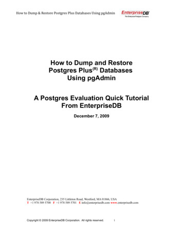
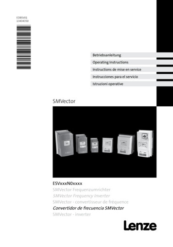
2Controller-based Automation: Central motion control2Controller-based Automation: Central motion controlThe Lenze "Controller-based Automation" system serves to create complex automation solutionswith central motion control. Here, the Controller is the control centre of the system.System structure of the Controller-based Automation[2-1]10Example: EtherCAT bus system with Controller 3231 C, I/O system 1000 and Servo-Inverter i700Lenze · Backup & Restore · Software Manual · DMS 2.0 EN · 11/2016 · TD17
2Controller-based Automation: Central motion controlLenze provides especially coordinated system components: Engineering softwareThe Lenze Engineering tools on your Engineering PC (Windows operating system) serve toparameterise, configure, and diagnose the system. The Engineering PC communicates with theController via Ethernet.The Lenze engineering tools are provided for download at:www.lenze.com Download Software Downloads ControllersThe Lenze Controller is available as Panel Controller with integrated touch display and asCabinet Controller in control cabinet design.Cabinet Controllers provide a direct coupling of the I/O system 1000 via the integratedbackplane bus. Bus systemsEtherCAT is the standard "on-board" bus system of the Controller-based Automation. EtherCATenables the control of all nodes on one common fieldbus.Optionally, CANopen, PROFIBUS and PROFINET can be used as extended topologies.For Controllers 3200 C and p500, the Ethernet interfaces also allow for the use of EtherNet/IP.Controllers c300 and p300 are provided with an "on board" CANopen interface (in addition toEtherCAT). Inverter (e.g. Servo-Inverter i700)"Application software" of the Lenze ControllersThe "application software" of the Lenze Controllers enables the control and/or visualisation ofmotion sequences.FAST technology modules provide for an easy development of a modular machine control in the»PLC Designer«.The following "Application software" versions are provided: "FAST Runtime"The sequence control takes place (by logically combined control signals) in the Controller.The motion control takes place in the inverter. "FAST Motion"The sequence control and the motion control take place in the controller.The inverter merely serves as actuating drive.Motion applications place special requirements on the cycle time and real-time capability of thebus system between the Controller and the subordinate fieldbus nodes. This is for instance thecase if the nodes are to be traversed with each other in a synchronised fashion, or if positionsetpoints are to be transmitted. "Visualisation"The optional visualisation of the automation system can be used separately or in addition to"FAST Runtime" or "FAST Motion".For this purpose, an external monitor panel/display can be connected to the Cabinet Controller3231 C/3241 C/3251 C.Lenze · Backup & Restore · Software Manual · DMS 2.0 EN · 11/2016 · TD1711
2Controller-based Automation: Central motion controlFieldbus communicationThe Lenze controllers have different interfaces for fieldbus communication:RangeCabinet ControllerPanel Controllerc3003200 C seriesp300p500Ethernet1212EtherNet/IP-Interfaces (on board)-EtherCAT1 1)11 1)1CANopen1-1 2)-Optional interfaces (communication cards)CANopenMC-CAN2- - 2)PROFIBUS masterMC-PBM- - PROFIBUS slaveMC-PBS- - PROFINET deviceMC-PND EthernetMC-ETH- - Serial interfacesMC-ISI- - 1) Only the master functionality is supported.2) Up to release 3.9: "EL 100 CAN" driver / from release 3.10: "Lenze CAN driver"Ethernet interfaceThe Ethernet interface serves to connect the Engineering PC or to create line topologies (nointegrated switch for Controller c300/p300).With Controllers 3200 C and p500, EtherNet/IP communication is also established via the Ethernetinterfaces.12Lenze · Backup & Restore · Software Manual · DMS 2.0 EN · 11/2016 · TD17
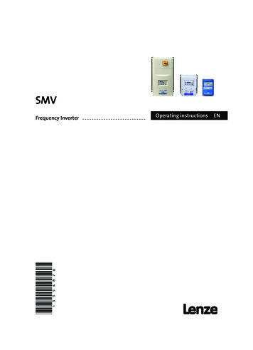
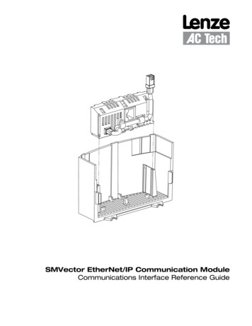
3Basic concept3.1Storage media used3Basic conceptThe following sections contain information on the functional principle of »Backup & Restore«.3.1Storage media usedThe Lenze Controller manages the software within an internal flash memory and on the SD memorycard.[3-1]Storage media used»Backup & Restore« allows for saving and restoring the data of the internal flash memory and theSD card on a USB flash drive.Internal flash memoryThe Lenze Controllers are provided with an internal flash memory. This memory contains the operating system and the Lenze software. The Controller boots from this memory. Since this memory is fixedly installed in the device, the data stored must be saved by means of»Backup & Restore«.SD cardThe SD card serves to save project data in the Lenze Controller.»Backup & Restore« saves the data of the SD card.Lenze · Backup & Restore · Software Manual · DMS 2.0 EN · 11/2016 · TD1713
3Basic concept3.1Storage media usedUSB deviceThe USB device is the central storage medium for performing backup, restore, and update processes. Note!Only use USB devices approved by Lenze. Only USB devices approved by Lenze ensureperfect functionality.Currently approved models and memory sizes can be gathered from the current Lenzesales documents. Tip!Current documentation and software updates with regard to Lenze products can be foundin the download area at:www.lenze.com14Lenze · Backup & Restore · Software Manual · DMS 2.0 EN · 11/2016 · TD17
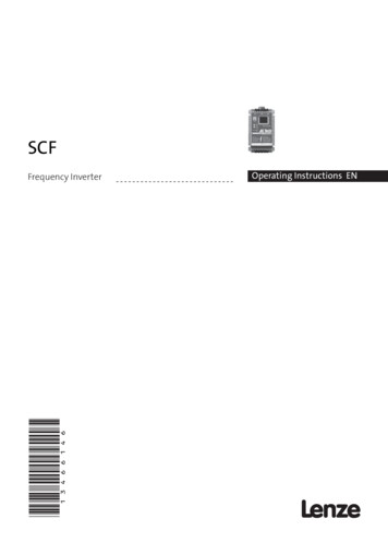
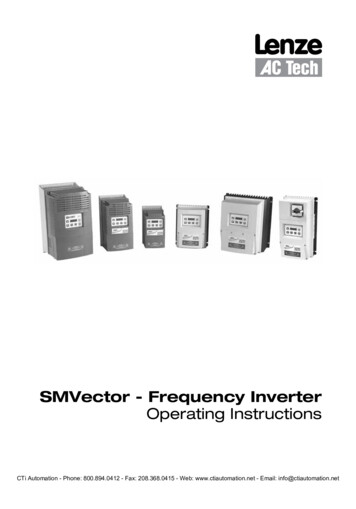
3Basic concept3.2Functions of the »Backup & Restore«3.2Functions of the »Backup & Restore«»Backup & Restore« enables the following actions: "Backup" (saving the data and operating system of a Lenze Controller) "Restore" (restoring the data and operating system of a Lenze Controller); "Data Restore" (restoring only data for Controller c300/p300) "Update" (updating the operating system of a Lenze Controller) "Auto Restore/Update" (optimises the performance of series commissioning)3.2.1BackupA backup saves the whole data base of a Lenze Controller The backup saves the following permanently stored data bases of the Controller: Operating system of Software Project data A backup provides the basis for being able to carry out a restore process in the event of an error.We recommend the regular creation of backups to avoid data losses.Functional principle of a backup[3-2]Functional principle of a backup When a backup is created on the Controller, components (from the internal flash memory andthe SD card) are copied to the USB flash drive. The USB device is the storage medium for the backup processes. A backup always comprises thecontents of the internal flash memory and the SD card. A backup is created manually. Creating a backup ( 23)Lenze · Backup & Restore · Software Manual · DMS 2.0 EN · 11/2016 · TD1715
3Basic concept3.2Functions of the »Backup & Restore«3.2.2Restore and auto-restoreRestoring a (previously created) backup is referred to as a restore.Restore and auto-restore are identical in terms of their data contents. They merely differ with regardto their use (one-time restoration or multiple restorations of the data).Functional principle of restore and auto-restore[3-3]Functional principle of restore and auto-restoreA restore writes the (previously saved) backup data from the USB device back to the internal flashmemory and the SD card. In the case of a restore, first a safety backup is created, in order to be able to restore the originalstate in the event of an error. In the case of an auto-restore, no safety backup is performed. In the case of an auto-restore, a restore without a safety backup is performed.Differences between a restore/auto-restoreRestore One-time restoration of a backup that has beenconfigured beforehand. Select this process to restore the data bases of abackup on an individual Controller. When a restore is carried out, a safety backup iscreated beforehand.16Auto-restore Multiple restorations of a backup on an optionalnumber of Controllers without further configuration. When the USB device is connected to a furtherController, the auto-restore is executed automatically(series commissioning). When an auto-restore is carried out, a restore isexecuted directly. The system does not create a safetybackup beforehand.Lenze · Backup & Restore · Software Manual · DMS 2.0 EN · 11/2016 · TD17
3Basic concept3.2Functions of the »Backup & Restore«3.2.3Data Restore (only Controller c300/p300)From release 3.14 onwards, the Data Restore feature is available for the Controllers c300 and p300.In case of a data restore, only the contents of the SD card of a (previously created) backup aretransmitted to the Controller. Within a hardware version, both a restore and a data restore can beused. If backups of release 3.8 to 3.13 are to be updated to a newer hardware version, this must bedone via a data restore.Functional principle of data restore[3-4]Functional principle of restore and auto-restoreA data restore writes the (previously saved) backup data from the USB stick back to the SD card.In case of a data restore, first a safety backup is created in order to be able to restore the originalstate in the event of an error (one-time restoration of a backup).Lenze · Backup & Restore · Software Manual · DMS 2.0 EN · 11/2016 · TD1717
3Basic concept3.2Functions of the »Backup & Restore«3.2.4Update and auto-updateDuring an update, the Lenze operating system is updated (only available for control technology).Update and auto-update are identical in terms of their data contents. Use an auto-update to carryout an update on several Controllers successively: series commissioning.Where can I receive an update and auto-update?Current documentation and software updates with regard to Lenze products can be found in thedownload area at:www.lenze.comFunctional principle of update and auto-update[3-5]Functional principle of update and auto-update »Backup & Restore« updates the software of the Controller. An update transfers the data fromthe USB flash drive to the internal flash memory (Flash). In the case of an update first a safety backup is created, in order to be able to restore the originalstate in the event of an error. When an auto-update is performed, no safety backup is created. An optional number ofControllers can be provided successively with this update.Differences between an update and an auto-updateUpdateAuto update One-time update of the Controller software Select this process in order to update the software onan individual Controller. When an update is performed, a backup is createdbeforehand for the purpose of safety.18 Multiple updates of the Controller software, on anoptional number of Controllers in succession. After connecting the USB device to a furtherController, the auto-update is started automatically:series commissioning. When an auto-update is carried out, an update isexecuted directly. The system does not create abackup beforehand.Lenze · Backup & Restore · Software Manual · DMS 2.0 EN · 11/2016 · TD17
3Basic concept3.3Standard procedure3.3Standard procedureTo carry out »Backup & Restore«, corresponding software applications are pre-installed on theController.The »Backup & Restore« functionality can be executed by means of the following softwareapplications:Software application»Backup & Restore« on the Engineering PCOperatingsystem ofEngineering PCOperating system ofControllersWindows XP/7Windows CE/EmbeddedCompact 7Windows EmbeddedStandard --- Example: »Backup & Restore« with Windows 7»Backup & Restore« on the ControllerExample: »Backup & Restore« with Windows CELenze · Backup & Restore · Software Manual · DMS 2.0 EN · 11/2016 · TD1719
3Basic concept3.3Standard procedureSoftware applicationOperatingsystem ofEngineering PC»WebConfig«(as an alternative for remote access via Engineering PC toa Cabinet Controller without monitor panel)Operating system ofControllersWindows XP/7Windows CE/EmbeddedCompact 7Windows EmbeddedStandard -- (via remote access toWindows CE)Example: »Backup & Restore« with »WebConfig«Windows Explorer(as an alternative, if no (executable) Controller isavailable) Example: »Backup & Restore« with Windows Explorer (Windows XP)»Backup & Restore« The software writes a control file to the USB device. The control file is evaluatedby the system at the next restart. Then the action selected is executed.Cabinet Controllers with a DVI interface provide for the connection of an external monitor panel.The panel that can be connected optionally makes it possible to monitor the progress of the actions.The current processing state is shown via the status LEDs. Status LEDs of the Controllers ( 37)Depending on the action selected, the Controller is restarted automatically after the process hasbeen carried out successfully, or a signal is output and it is waited until the USB device is removedand the Controller is restarted manually.20Lenze · Backup & Restore · Software Manual · DMS 2.0 EN · 11/2016 · TD17
3Basic concept3.4Signalling of the processing state3.4Signalling of the processing stateWhen an error occurs, it is indicated via the Status LEDs of the Controllers ( 37) and by a textmessage on the screen.Signal transmitterDescriptionStatus LEDs on the ControllerThe Controllers are equipped with status LEDs representing the currentoperating status. When a backup, restore, or update is carried out, the LEDs Error andStatus 1 indicate the processing progress or a possible error status. On an optionally connected panel (screen) texts showing status and errormessages can be read.»Backup & Restore«Software applicationThe »Backup & Restore« application provides status information in the formof dialog windows. On an optionally connected panel (screen) texts showing status and errormessages can be read. When an update is carried out (only available for control technology),status messages are written. The status messages can be viewed via the»WebConfig« logbook function.»WebConfig«The »WebConfig« indicates the respective status by displaying a text in thecorresponding code:Lenze · Backup & Restore · Software Manual · DMS 2.0 EN · 11/2016 · TD1721
4Carrying out backup/restore/update4Carrying out backup/restore/updateA backup, restore or update can be carried out in the following ways:A. On the Engineering PC via . »Backup & Restore« application, »WebConfig«, Windows Explorer.B. Directly on the Controller via »Backup & Restore« application (Windows CE). Tip!Use the »WebConfig« for Cabinet Controllers without external monitor panel.Feasibility of backup/restore/update for Lenze ControllersActionCabinet ControllerPanel Controller/HMI3221 C3231 C3241 C3251 Cc300p500p300 Creating a backup on the Controller ( 25)- - Creating a backup using the »WebConfig« ( 26) Creating a backup with the Windows Explorer (on thedirectory/file level) ( 27) Carrying out a restore on the Engineering PC(recommended variant) ( 29) Carrying out a restore on the Controller ( 30)- - Carrying out a restore with the »WebConfig« ( 31) Carrying out a restore with the Windows Explorer (onthe directory/file level) ( 32) Carrying out an auto-restore ( 33) Carrying out a data restore on the Engineering PC ( 34)-- - Carrying out a data restore on the Controller ( 35)---- BackupCreating a backup on the Engineering PC (recommendedvariant) ( 24)Restore/auto-restoreData restoreUpdate/auto updateCarrying out an update/auto-update (only available forcontrol technology) ( 36) Backup/restore/update possible. Backup/restore/update under Windows CE is only possible with connected monitor panel.-22Backup/restore/update not possible.Lenze · Backup & Restore · Software Manual · DMS 2.0 EN · 11/2016 · TD17
4Carrying out backup/restore/update4.1Creating a backup4.1Creating a backup Note! A backup saves all data of the Controller (data of the internal flash memory and theSD card). In order to successfully create a backup, the USB device must have sufficient memorycapacity.Guide values for the size of a backup file: Windows CE 6.0: 150 MB (3200 C/p500) Windows Embedded Compact 7: 400 MB (c300/p300) Windows Embedded Standard: 2 GB The free memory capacity of the USB device at least has to be half of the SD cardcapacity 2 GB (guide value for Windows Embedded Standard). After having carried out the backup, remove the USB device from the Controller.Parts of the backup nameThe name of the »Backup & Restore« directory is composed as follows: prefix controller serialname date time number operatingsystem backupExample:IPCBackup p300 30000006145423 CE 3 14 0 Winder 20160909 111033Lenze · Backup & Restore · Software Manual · DMS 2.0 EN · 11/2016 · TD1723
4Carrying out backup/restore/update4.1Creating a backup4.1.1Creating a backup on the Engineering PC (recommended variant) How to carry out a backup on the Engineering PC:1. Connect a USB device to the Engineering PC.2. Start »Backup & Restore« on the Engineering PC.3. Change to the Backup tab.4. Select the5. Assign aUSB stick.backup name in the input field (length: 2 - 16 characters). Parts of the backup name ( 23)6. Click theStart button.A control file is written to the USB device into the "/Backup" directory.7. Remove the USB device from the Engineering PC.8. Connect the USB device to the Controller of which you want to create a backup.9. Restart the Controller (with connected USB device) by mains switching.If Windows CE systems are used, the Controller is restarted automatically.10. After starting the Controller, remove the USB device from the Controller.24Lenze · Backup & Restore · Software Manual · DMS 2.0 EN · 11/2016 · TD17
4Carrying out backup/restore/update4.1Creating a backup4.1.2Creating a backup on the Controller Note!Cabinet Controllers with DVI interface (3231 C, 3241 C, 3251 C) require an externalmonitor panel. How to carry out a backup on the Controller:1. Connect a USB device to the USB interface of the Controller.2. Start »Backup & Restore« on the Controller.3. Change to the Backup tab.4. Assign abackup name in the input field (length: 2 - 16 characters). Parts of the backup name ( 23)5. Click theStart button.A control file is written to the USB device into the "/Backup" directory.6. Restart the Controller (with connected USB device) by mains switching.If Windows CE systems are us
1 About this documentation 4 Lenze · Backup & Restore · Software Manual · DMS 2.0 EN · 11/2016 · TD17 More technical documentation for Lenze components Further information on Lenze products which can be used in conjunction with Controller-based