Transcription
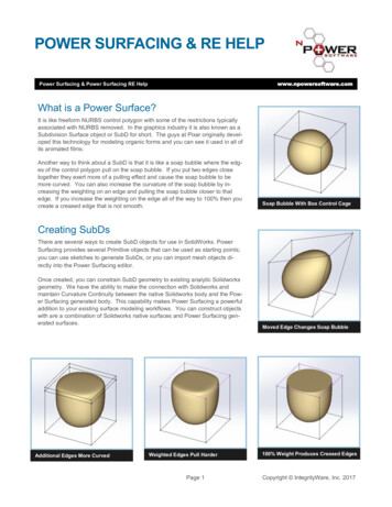
POWER SURFACING & RE HELPwww.npowersoftware.comPower Surfacing & Power Surfacing RE HelpWhat is a Power Surface?It is like freeform NURBS control polygon with some of the restrictions typicallyassociated with NURBS removed. In the graphics industry it is also known as aSubdivision Surface object or SubD for short. The guys at Pixar originally developed this technology for modeling organic forms and you can see it used in all ofits animated films.Another way to think about a SubD is that it is like a soap bubble where the edges of the control polygon pull on the soap bubble. If you put two edges closetogether they exert more of a pulling effect and cause the soap bubble to bemore curved. You can also increase the curvature of the soap bubble by increasing the weighting on an edge and pulling the soap bubble closer to thatedge. If you increase the weighting on the edge all of the way to 100% then youcreate a creased edge that is not smooth.Soap Bubble With Box Control CageCreating SubDsThere are several ways to create SubD objects for use in SolidWorks. PowerSurfacing provides several Primitive objects that can be used as starting points;you can use sketches to generate SubDs, or you can import mesh objects directly into the Power Surfacing editor.Once created, you can constrain SubD geometry to existing analytic Solidworksgeometry. We have the ability to make the connection with Solidworks andmaintain Curvature Continuity between the native Solidworks body and the Power Surfacing generated body. This capability makes Power Surfacing a powerfuladdition to your existing surface modeling workflows. You can construct objectswith are a combination of Solidworks native surfaces and Power Surfacing generated surfaces.Additional Edges More CurvedWeighted Edges Pull HarderPage 1Moved Edge Changes Soap Bubble100% Weight Produces Creased EdgesCopyright IntegrityWare, Inc. 2017
Table Of ContentsPower Surfacing HelpWhat is a Power Surface? .1Creating SubDsFrom the Power Surfacing Menu.6Primitive Creation .6Create From Box, Torus, Cylinder, Planar Surface, Cone .7Mid Plane, Rotation Offset .8Creation Plane .9Create By Drawing on Plane .9Create From Sketch .10Viewing .11Selection .12Gizmos/Triad .13Property ManagerFeature Creation Settings .15, 16Selection Utility Panel . 17 - 22Viewing Panel .23Hot Keys and Shortcuts . 24DialogsSelection Options (filters) . 25 - 27Selected Vertex Editor .27Sectioning Options .28Advanced Triad Options .29, 30Alignment Tools .31Selection Set Manager .32Command History Player.33SubD Checker.34Tools and Flyouts .35, 36Extrude .37Hinge .38Insert Loops .39Offset Loops .40Hard Edge .41Smooth Edge .42Page 2Copyright IntegrityWare, Inc. 2017
Table Of Contents (continued)Chamfer . 43Erase . 44Delete . 44Bridge. 45Merge Vertices . 46Sew . 47Unsew . 48Quad Fill . 49Face Fill. 50Insert Edges . 51Relax . 52Curve . 53Quadize . 54Level Of Detail. 55, 56Mirror . 57, 58Boundary Tools . 59Reference Tools . 60 -62Import Reference . 62To Face . 63To Edge . 64, 65To Vertex . 66Override Constraint . 67Retain Offset . 68Spatial Constraint . 69Alignment Tools . 70Subdivide All. 71Subdivide Selected . 72Bend . 73Twist. 74Page 3Copyright IntegrityWare, Inc. 2017
Table Of Contents (continued)Thicken .75Normal Push.76Flip All Faces and Flip Selected Faces .76Slice .77Select by Angle .77Extend .78Zebra .79Curvature.79Export Options.80Options .81, 82Import .82Power Surfacing RE HelpWhat is Retopologizing? . 83What can be Retopologized? . 83Workflow Scenarios. 84Retopologizing vs. Constraints . 85General Workflow . 85Obtaining a Reference Mesh .86Retopo Basics .86Adjusting the Reference Mesh Display .87Vertex Attributes .88Using Shrink Wrap .88Checking Accuracy.89Modifying the Interpolated Mesh .89Converting the Retopo Mesh to CAD .90Preparing the Reference Mesh .91Importing the Reference Mesh .91Removing Isolated Geometry .92Removing Unwanted Geometry .93Selections Sets. 94 - 96Creating Proxy Surfaces .97Page 4Copyright IntegrityWare, Inc. 2017
Table Of Contents (continued)The Retopologize Tools Rollout . 98, 99Edit Reference Mesh . 100Select by Element Workflow . 101Mesh Orientation Tools . 102Edit Selected Workflow. 103 - 105Retopologize Object . 106Add Selected To Mesh . 106Create Poly From Reference . 107Bounding Box . 107Quad Wrap . 108Add Constraint . 109Remove Constraint. 109Snap Vertices . 110Draw Edges . 110Paint Faces . 111Face Grid . 112Wrap Around . 112Smart Fill. 113Glue Edge Groups . 113Paint Relax. 114Shrink Wrap . 115Clear Shrink Wrap . 116Distance . 116 - 118Page 5Copyright IntegrityWare, Inc. 2017
From the Power Surfacing MenuYou can create both the Part file and the SubD model directly from the Power Surfacingmenu when you select one of the Power Surfacing primitive objects. It is also possibleto create most of the primitives while already in editing mode to add a primitive to theexisting SubD.Default Torus ShapeCylinder ShapeDefault Cone ShapePage 6Copyright IntegrityWare, Inc. 2017
Create Box, Torus, Cylinder, Planar Surface, ConePower Surfacing lets you choose between Box, Torus, Cylinder, Plane and Cone primitive objects for use as the starting Control Mesh. Each allows you to set its various parameters. You must click the Accept check mark to start editing the new SubD. You cancancel the creation by clicking the red X.The Planar Surface is an open edged SubD object. If you are used to creating with surfaces rather than volumes you may wish to use this option to start your SubD. If youplan on extending the edges upward, you may want to use the Flip Normals option before creation.Flip SubD Normals—Normal left image; flipped right imagePage 7Copyright IntegrityWare, Inc. 2017
Mid PlaneAll Primitives have the option to be extruded from the Create Plane upward or, if checked, from Mid Plane.Extruded up from the plane (left image); and extruded mid-plane (right image)Rotation OffsetPrimitive objects can also be rotated to an offset during the create process. Checking Offset Rotation bringsup a text box that allows you to type in the rotation in degrees.The left plane uses no rotation offset; the right plane is set to 45 degreesPage 8Copyright IntegrityWare, Inc. 2017
Creation Plane (all primitives)In the Creation Plane section, you can set the creation plane and change the default orientation for the primitive by selecting it from the Feature Tree in the viewport. The selected plane will appear in both the selection list box and in the viewport.Create By Drawing On PlaneYou can start a model by drawing directly on a datum plane. As you draw, it will fill inquads automatically. This command, like other primitives, can also be used in an existingobject to add faces to the model on a given plane. Note that the resulting faces are onthe datum plane, but not constrained to the datum plane. Therefore points can be movedoff the plane in subsequent editing operations.Page 9Copyright IntegrityWare, Inc. 2017
Create From SketchYou may use sketches to create the SubD solid by selecting the Create From Sketchoption from the creation dropdown. If the sketch was selected prior to selecting CreateFrom Sketch, it will automatically be put into the Sketch Selection box. If it was not selected, selecting any part of the sketch is sufficient. If the sketch is not visible, you canselect it from the Feature Tree in the viewport.With a sketch selected, you will need to select either Create Solid SubD From Sketch,or Create Planar SubD From Sketch. With a Solid, you have the option to extrude theSubD up from the create plane or mid plane, just as with the primitives. Preliminaryextrusion height is calculated using the average edge length, but is easy to adjust oncein Power Surface edit mode.The sketch will do it’s best to approximate the curves with the subdivided mesh.Note that the association with the sketch is not maintained and you are free to edit theresulting SubD model in any way you see fit.Left Top: original sketch; Middle Top: Default solid with 10% Quad Size; Right Top: uncheck Crease Corner VerticesLeft Bottom: 4% Quad Size Scale; Right Bottom: 12% Quad Size Scale.Page 10Copyright IntegrityWare, Inc. 2017
ViewingWhile setting up the creation method for your SubD, you can also change the display mode. The top three iconschange display from Display Control Polygon, Display the SubD, and SubD Mesh with the Control Edges and Vertices. The bottom three icons allow you to change the visibility of the Faces, Edges, and Vertices. Sometimes youmay want to see the shape without the edges.The images are from left to right: Control Mesh, SubD Mesh, SubD Mesh Faces plus Control Cage, Control Cagebox with additional subdivisions.Page 11Copyright IntegrityWare, Inc. 2017
SelectionRegion SelectPower Surface follows the same conventions as SolidWorks for region select. Dragging from right to left selects in crossingmode, where sub-objects crossed by the marquee will be selected. In windowed mode, dragging from left to right, only thesub-objects fully within the marquee will be selected.When using the selection marquee, back-facing objects will be selected along with those on the front.GeneralFaces, edges and vertices are previewed in hover mode with orange highlight. When selected, or picked, the sub-object orsub-objects will turn cyan colored.To add to the selection, you can hold down the ctrl key. To remove sub-objects from the selection, you can hold the shift keydown.Status BarThe number and type of currently selected vertices, edges or faces are shown on the status bar, lower left. Depending on theselection, it may also show location, length, weight, or other pertinent information.Smart Selection (Double Clicking)In Edge selection or Any selection mode, the position of the cursor over the edge will determine if an edge loop or edge ringwill be selected. Double clicking the outer third of the edge will select a loop, while double clicking the center third will selecta ring. With faces, the edge nearest the cursor will determine the direction of the face loop. Zoom in closer for more accuracy.Soft SelectionSelections can also be "soft." The influence of transforms can be set to expand beyond the selection, diminishing with distance.Page 12Copyright IntegrityWare, Inc. 2017
Gizmos/TriadPower Surfacing has its own unique context aware gizmo. Besides the usual transforms, move, rotate and scale, you willbe able to access many of the command's advanced parameters right in the viewport.The Transform Triad or GizmoThe Transform gizmo provides access to Move, Rotate and Scale with bothsingle and dual axis functionality. Uniform scale is performed by using thecenter of the gizmo. Use the Wedge shaped portion of the gizmo forRotatedual axis moves. Use the diamond shaped portion to perform dualaroundaxis scales.AxisScale in AxisMove along AxisScale AllMove inPlaneScale inPlaneSpecialty GizmosThe Expand gizmo allows you to increase or decrease the sizeof a face or sub-object selection during extrudes or bevels.The Rotation gizmo allows you to rotate the selected subobjects while the command using it is active.The Increment Value gizmo allows you to increase segments inExtrude, Bridge and Insert Loops commands. With PartialCrease activated, it lets you change the crease amount on selected edges.The Value Adjustment gizmo allows you to adjust float valuespertaining to the current command while active. Commandssuch as Bridge allow the tension at either end to be adjusted. Commands such as Insert Loops allow you to Slide or Pinchthe previewed edge loops.Page 13Copyright IntegrityWare, Inc. 2017
Property ManagerAccept, Cancel, Undo, RedoAccept and Cancel are context sensitive commands. When you are in themiddle of an operation that needs to be ended, such as Extrude or InsertLoops, the Accept command will finish or end the operation.When no operation is in progress, the commands will act as follows:The OK ,or Accept button, represented by the green check mark,will convert the Power Surfacing model to a BREP or NURBS model thatcan then be modified with the usual SolidWorks features.The Cancel button, represented by the red check mark, will abandon any edits done to thePower Surfacing model since the last conversion.Undo , Ctrl ZUndoes the last action performed on the SubD. This includes selections, but stays separate fromSolidWorks commands. The SubD's construction stack remains independent of conversions allowingyou to be able to undo previous actions after returning to edit the SubD after a conversion.Redo, Ctrl XReverses the last undo command.Page 14Copyright IntegrityWare, Inc. 2017
Feature Creation SettingsPost ProcessingThe post processing option allows additional flexibility when constraining to existing Solidworkssurfaces as follows:Create 3D Sketch: this option creates a 3D sketch along the edges where the Power Surfacegeometry joins the Solidworks geometry. This sketch can be used in conjunction with the Trimand Knit commands to build up a solid from surfaces.Delete and Knit: this option is primarily used when attaching a Power Surface to a face orfaces of an existing Solidworks body. This operation will automatically delete faces in the original body that are used by the Power Feature. Then it will knit the remaining faces from thedelete with the faces produced by the Power Feature and often produce a resulting solid body.It is even possible to use a Power Feature to connect two separate bodies.Vertex AdjustmentThis option allows the user to override what happens to unconstrained vertices in the PowerFeature when an underlying parametric change occurs as follows:No Adjustment: unconstrained vertices are not moved (default)Retain Distance: unconstrained vertices maintain a constant distance from the reference geometry they are closest to. For example if you are constraining to a cylinder and the cylindersize grows from 75mm to 100mm, all unconstrained vertices will be moved out by 25mm whenthe parametric update occurs.Fall Off Distance: unconstrained vertices will be moved in proportion to their distance from thereference geometry. In the above example, vertices near the cylinder would move close to25mm and vertices the furthest from the cylinder would move only slightly.Left to Right: 1) Original SubD constrained to a cylinder which will change radius; 2) No Adjustment option; 3) Retain Distance option; 4) Fall Off Distance option.Page 15Copyright IntegrityWare, Inc. 2017
Feature Creation Settings (continued)QualityThis option allows the user to control the quality which the conversion to Solidworks geometryis processed at. Note that the higher settings will yield larger file sizes and slower processing,but will give more precise results. It is also possible to control this setting directly using ManualOverride. If you have a very heavy quad mesh, for example something from Z-brush, this option will allow you to set the conversion to Zero Subdivisions and Zero Finer Subdivisions.Quality- Coarse, Medium, Fine, Very Fine, or Manual OverrideType- Normal, 1 to 1 Planar, 1 to 1 NURBSNormal converts the SubD to a minimal number of NURBS surfaces.1 to 1 Planar converts the control mesh to a NURBS body with only planar surfaces. Use thisoption for a quick way to save the part file without waiting for a full convert.1 to 1 NURBS converts the SubD creating one NURBS surface for each face in the controlmesh. Use this option when you need to register features from particular SubD edges. SomeFeatures, such as Fillet may need the edges reselected after edits to the SubD.Manual Override Notes:1)Typically very heavy and smooth quad meshes from programs like Z-Brush will convertwith zero in both options. You can convert models with 1 million to 5 million quads thisway.2)The total number of subdivision should be no more than 6. If you want 4 Subdivision Levels, you should put no more than 2 Finer Subdivision Levels.3)The subdivision levels for Course, Medium, Fine, and
There are several ways to create SubD objects for use in SolidWorks. Power Surfacing provides several Primitive objects that can be used as starting points; you can use sketches to generate SubDs, or you can import mesh objects di-rectly into the Power Surfacing editor. Once created, you can constrain SubD geometry to existing analytic Solidworks