Transcription
SMVector EtherNet/IP Communication ModuleCommunications Interface Reference Guide
About These InstructionsThis documentation applies to the optional EtherNet/IP communications module for the SMVector inverter andshould be used in conjunction with the SMVector Operating Instructions (Document SV01) that shipped with thedrive. These documents should be read in their entirety as they contain important technical data and describe theinstallation and operation of the drive. 2009 Lenze AC Tech CorporationAll rights reserved. No part of this manual may be reproduced or transmitted in any form without written permissionfrom Lenze AC Tech Corporation. The information and technical data in this manual are subject to change withoutnotice. Lenze AC Tech Corporation makes no warranty of any kind with respect to this material, including, but notlimited to, the implied warranties of its merchantability and fitness for a given purpose. Lenze AC Tech Corporationassumes no responsibility for any errors that may appear in this manual and makes no commitment to update orto keep current the information in this manual.CompoNet , DeviceNet , CIP , CIP Safety , CIP Sync , CIP Motion , DeviceNet Safety and EtherNet/IPSafety and all related indicia are trademarks of the ODVA (Open DeviceNet Vendors Association). EtherNet/IP is a trademark used under license by ODVA.RSLogix , RSLogix 5000, CompactLogix, CompactLogix 5000, ControlLogix , MicroLogix , SoftLogix,Allen Bradley and all related indicia are either registered trademarks or trademarks of Rockwell Automation Corporation.
Contents1Safety Information.11.123Warnings, Cautions and Notes. 11.1.1General. 11.1.2Application. 11.1.3Installation. 11.1.4Electrical Connection. 21.1.5Operation. 2Introduction.32.1EtherNet/IP Overview. 32.2Ethernet TCP/IP Configuration. 42.2.1MultiCast Configuration. 42.2.2IGMP Implementation. 42.2.3TCP/IP Sockets. 52.2.4CIP Connections. 52.3Module Specification. 52.4Module Identification Label. 5Installation.63.1Mechanical Installation. 63.2Electrical Installation. 73.2.1Ethernet RJ-45 Socket. 73.2.2Grounding. 73.2.3Cabling. 83.2.4Maximum Network Length. 83.2.5Minimum Node to Node Cable Length. 83.2.6Network Topology. 93.2.7Example Networks. 10iCMVETH01B
Contents4Commissioning.114.14.2Connect to the Drive. 114.1.1Configuring the PC IP Address (Windows XP). 114.1.2Configuring the SMVector Drive. 15Configuring the SMV EtherNet/IP Module. 174.2.1Connecting. 174.2.2Setting the Network Protocol. 174.2.3IP Address. 174.2.4Network Mask. 174.2.5Gateway Address. 174.2.6Multicast Address. 174.2.7TTL Value. 184.2.8Configuration Control. 184.2.9Duplex Control. 184.2.10 Interface Speed Control. 184.2.11 Non-Module Parameter Settings. 184.35Configuring the Network Master. 194.3.1Master Support Files. 194.3.2Configuring a Scanner or Bridge. 194.3.3Adding a Bridge or Scanner to the I/O Configuration. 19Cyclic Data Access.235.1Implicit (I/O) Messaging. 235.2Implicit Messaging Timeout. 275.3Saving the Configuration. 275.4I/O Assemblies. 285.4.1Important Note on Input Assemblies. 285.4.2Important Note on Output Assemblies. 285.5Using Assemblies for Control and Status/Data Monitoring. 285.6Output Assemblies. 29CMVETH01B5.6.1Output Assembly 20 - Basic Speed Control. 295.6.2Output Assembly 21 - Extended Speed Control. 295.6.3Output Assembly 100 - Speed (Hz) & Digital and Analog Output. 305.6.4Output Assembly 102 - PID Setpoint & Digital and Analog Output. 315.6.5Output Assembly 104 - Torque Setpoint & Digital and Analog Output. 325.6.6Output Assembly 107 - Custom Selectable. 32ii
Contents5.76795.7.1Input Assembly 70 - Basic Speed Control. 375.7.2Input Assembly 71 - Extended Speed Control. 375.7.3Input Assembly 101 - Speed (Hz) & Digital and Analog Input. 385.7.4Input Assembly 103 - Speed (Hz) & Actual PID Setpoint and Feedback. 385.7.5Input Assembly 105 - Speed (Hz) & Actual Torque and Analog Input. 395.7.6Input Assembly 106 - Custom Selectable. 39Acyclic Data Access.476.1What is Acyclic Data?. 476.2Explicit Messaging. 476.3Explicit Messaging Timeout. 54Advanced Features.557.18Input Assemblies. 37Option Module Advanced Parameters. 557.1.1Module Revision. 557.1.2Module Status. 557.1.4Module Time-out Action. 557.1.5Initialize Ethernet/IP Settings. 557.1.6Module Firmware. 55Diagnostics.568.1Faults. 568.2Troubleshooting. 56Reference.579.1Parameter Reference. 579.2Object Specifications. 629.2.1Identity Object - Class 0x01 (1 dec). 629.2.2Message Router Object - Class 0x02 (2 dec). 629.2.3Assembly Object - Class 0x04 (4 dec). 639.2.4Connection Manager Object - Class 0x06 (6 dec). 649.2.5Parameter Object - Class 0x0F (15 dec). 659.2.6Parameter Group Object - Class 0x10 (16 dec). 659.2.7Motor Data Object - Class 0x28 (40 dec). 669.2.8Control Supervisor Object - Class 0x29 (41 dec). 679.2.9AC/DC Drive Object - Class 0x2A (42 dec). 689.2.10 TCP/IP Interface Object - Class 0xF5 (245 dec). 699.2.11 Ethernet Link Object - Class 0xF6 (246 dec). 70iiiCMVETH01B
Safety Information1Safety Information1.1Warnings, Cautions and Notes1.1.1GeneralSome parts of Lenze controllers (frequency inverters, servo inverters, DC controllers) can be live, movingand rotating. Some surfaces can be hot.Non-authorized removal of the required cover, inappropriate use, and incorrect installation or operationcreates the risk of severe injury to personnel or damage to equipment.All operations concerning transport, installation, and commissioning as well as maintenance must becarried out by qualified, skilled personnel (IEC 364 and CENELEC HD 384 or DIN VDE 0100 and IEC report664 or DIN VDE0110 and national regulations for the prevention of accidents must be observed).According to this basic safety information, qualified skilled personnel are persons who are familiar withthe installation, assembly, commissioning, and operation of the product and who have the qualificationsnecessary for their occupation.1.1.2ApplicationDrive controllers are components designed for installation in electrical systems or machinery. They arenot to be used as appliances. They are intended exclusively for professional and commercial purposesaccording to EN 61000-3-2. The documentation includes information on compliance with EN 61000-3-2.When installing the drive controllers in machines, commissioning (i.e. the starting of operation as directed)is prohibited until it is proven that the machine complies with the regulations of the EC Directive 2006/42/EC (Machinery Directive); EN 60204 must be observed.Commissioning (i.e. starting drive as directed) is only allowed when there is compliance to the EMCDirective (2004/108/EC).The drive controllers meet the requirements of the Low Voltage Directive 2006/95/EC. The harmonisedstandards of the series EN 50178/DIN VDE 0160 apply to the controllers.The availability of controllers is restricted according to EN 61800-3. These products can causeradio interference in residential areas. In the case of radio interference, special measures may benecessary for drive controllers.1.1.3InstallationEnsure proper handling and avoid excessive mechanical stress. Do not bend any components and do notchange any insulation distances during transport or handling. Do not touch any electronic componentsand contacts. Controllers contain electrostatically sensitive components, which can easily be damaged byinappropriate handling. Do not damage or destroy any electrical components since this might endangeryour health! When installing the drive ensure optimal airflow by observing all clearance distances in thedrive's user manual. Do not expose the drive to excessive: vibration, temperature, humidity, sunlight, dust,pollutants, corrosive chemicals or other hazardous environments.1CMVETH01B
Safety Information1.1.4Electrical ConnectionWhen working on live drive controllers, applicable national regulations for the prevention of accidents (e.g.VBG 4) must be observed.The electrical installation must be carried out in accordance with the appropriate regulations (e.g.cable cross-sections, fuses, PE connection). Additional information can be obtained from the regulatorydocumentation.The regulatory documentation contains information about installation in compliance with EMC (shielding,grounding, filters and cables). These notes must also be observed for CE-marked controllers.The manufacturer of the system or machine is responsible for compliance with the required limit valuesdemanded by EMC legislation.1.1.5OperationSystems including controllers must be equipped with additional monitoring and protection devices accordingto the corresponding standards (e.g. technical equipment, regulations for prevention of accidents, etc.).You are allowed to adapt the controller to your application as described in the documentation.DANGER! After the controller has been disconnected from the supply voltage, do not touch the livecomponents and power connection until the capacitors have discharged. Please observe thecorresponding notes on the controller. Do not continuously cycle input power to the controller more than once every three minutes. Close all protective covers and doors during operation.WARNING!Network control permits automatic starting and stopping of the inverter drive. The system designmust incorporate adequate protection to prevent personnel from accessing moving equipmentwhile power is applied to the drive system.Table 1: Pictographs used in these instructionsPictographCMVETH01BSignal wordMeaningConsequences if ignoredDANGER!Warning of Hazardous ElectricalVoltage.Reference to an imminentdanger that may result in deathor serious personal injury if thecorresponding measures are nottaken.WARNING!Impending or possible dangerfor personsDeath or injurySTOP!Possible damage to equipmentDamage to drive system or itssurroundingsNOTEUseful tip: If observed, it willmake using the drive easier2
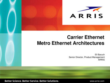
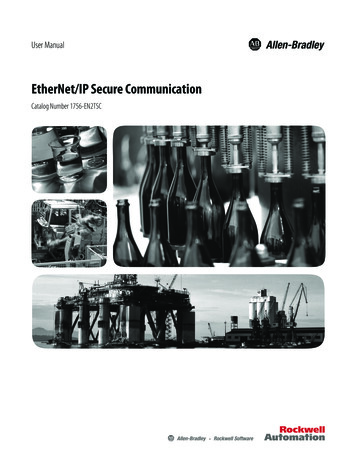
Introduction2IntroductionEtherNet/IP just like its close siblings DeviceNet and ControlNet, uses CIP (Common Industrial Protocola.k.a. Control and Information Protocol) to exchange data between devices on an Ethernet network. ACTech implementation of CIP follows the standard supported by the ODVA (governing organization) andsupports the two main types of EtherNet/IP communication: Explicit Messaging and I/O Messaging.The purpose of this document is to describe the EtherNet/IP implementation specifics for the SMV driveas well as provide the necessary information and examples for users and network programmers. Thisdocument assumes the reader is familiar with the general concept of CIP and has a basic knowledge ofEthernet TCP/IP communication principles.2.1EtherNet/IP OverviewEtherNet/IP implements network protocol using the seven layer Open Systems Interconnection (OSI) modelas illustrated in Figure 1. Ethernet has an active infrastructure and as such EtherNet/IP can support analmost unlimited number of point-to-point nodes. The EtherNet/IP system requires just one connection forconfiguration and control. An EtherNet/IP system uses peer-to-peer communication and can be setup tooperate in a master/slave or distributed control configuration.Layer7ApplicationCIP: Application Layer - Object Library6PresentationCIP: Data Management - Explicit Messages, I/O Messages5Session4Transport3Network2Data icalDeviceNetPhysical LayerControlNetPhysical LayerEthernetPhysical LayerCIP: Connection Management - Message ulationTCPUDPIPFigure 1: OSI Model3CMVETH01B
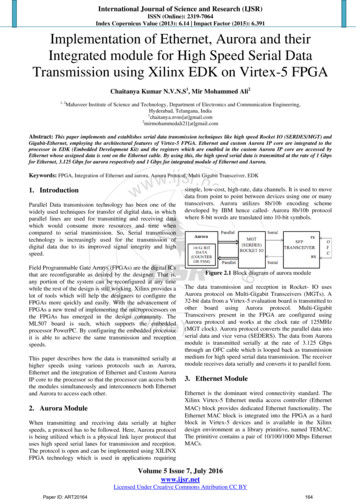
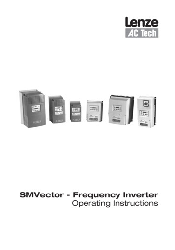
Introduction2.2Ethernet TCP/IP ConfigurationTypically, an EtherNet/IP network is made up of segments containing point-to-point connections in a starconfiguration as illustrated in Figure 2. At the center of this star topology is a bank of Ethernet 2 & 3switches that can support a great number of point-to-point ntityObjectAssemblyObjectMessage RouterObjectTCP/IP on ManagerObjectUCMMEthernet InterfaceObjectTCP/IP EthernetNetworkFigure 2: EtherNet/IP Star Configuration2.2.1MultiCast ConfigurationBy default the SMVector drive automatically generates the multicast address used for I/O messaging.The default multicast TTL (time to leave) value is 1 which means that the multicast I/O packets will bepropagated over the local subnet only.The user is allowed to explicitly set the drive’s multicast address and TTL values but this feature shouldbe used carefully. The TTL and Mcast Config attributes in the TCP/IP object are also implemented. Notethat the Num Mcast value in the Mcast Config attribute must always be 1. The user configurable SMVectorsystem variables for multicast are:2.2.2Variable IDMeaning426TTL422-425Multicast address (default 239.64.2.224)IGMP ImplementationThe IGMP v2 version of the IGMP (Internet Group Management Protocol) is used.015 167 8TypeMax Response Time23 24ChecksumGroup AddressMessage Type0x11 General Query0x12 v1 Report0x16 v2 Report0x17 v2 Leave0x22 v3 ReportMax Response TimeMaximum time the Querierwaits for report in responseto a membership queryChecksumThe 1’s complementof the entire IGMP messageGroup AddressIn a general query it is the multicast group addressIn other cases it is a specific multicast addressFigure 3: IGMP v2 Message FormatCMVETH01B431
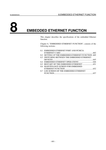
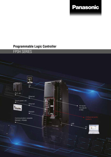
Introduction2.2.3TCP/IP SocketsThe SMVector drive supports up to 2 TCP/IP socket connections.2.2.4CIP ConnectionsThe SMVector drive supports up to 6 CIP connections.2.32.4Module Specification Auto detection of data rates Supported baudrates: 10 BaseT, 100 BaseT Scalable amount of input and output process data words (4 output, 4 input). Parameter access data channel To simplify setup and operation, implemented classes and behavior conform to the AC DRIVE profile asspecified in the ODVA Common Industrial Protocol (CIP) Specification.Module Identification LabelFigure 4 illustrates the labels on the SMV EtherNet/IP communications module. The SMVector EtherNet/IPmodule is identifiable by: Two labels affixed to either side of the module. The color coded identifier label in the center of the module.Right-hand Label:Ratings & CertificationsCOMM I/O ONLYS/N: 123456789LISTEDESVZAE0-000XX1A10Fieldbus Identifier:E EtherNet/IPLeft-hand Label:Module DataE0SMV ETHTYPE: ESVZAE0ID-NO: 12345678ESVZAC0-000XX1A10ABCDEA: Fieldbus ProtocolB: Model NumberC: Lenze Order NumberD: Firmware RevisionE: Hardware RevisionFigure 4: EtherNet/IP Module Labels5CMVETH01B
Installation3Installation3.1Mechanical Installation1. Ensure that the AC supply has been disconnected before opening the terminal cover.2. Insert the EtherNet/IP option module in the terminal cover and securely “click” into position as illustratedin Figure 5.3. Wire the network cables as detailed in paragraph 3.2, Electrical Installation to the connector providedand plug the connector into the option module.4. Align terminal cover for re-fitting, connect the module umbilical cord to the drive then close the coverand secure, as shown in Figure 6.NEMA 1NEMA 1NEMA 4NEMA 4Figure 5: Installing the EtherNet/IP Communications ModuleFigure 6: Re-Installing the Terminal CoverCMVETH01B6
Installation3.2Electrical Installation3.2.1Ethernet RJ-45 SocketThe ethernet interface on the SMV is an RJ-45 Ethernet socket used to communicate with a host viaEthernet TCP/IP. Table 2 identifies the terminals and describes the function of each.Table 2: P2 Pin Assignments (Communications)NameFunction1 TXTransmit Port ( ) Data Terminal2- TXTransmit Port (-) Data Terminal3 RXReceive Port ( ) Data Terminal4N.C.5N.C.6- RX7N.C.8N.C.RJ45 ConnectorP2ETHERNETPin18Receive Port (-) Data TerminalThe status LEDs integrated in the RJ-45 socket indicate link and activity. The green LED indicates whethera link is established with another network device. The yellow LED indicates link activity and flashes whendata is received by the EtherNet/IP module.3.2.2GroundingThe SMV EtherNet/IP module must be gounded. Attach the ground wire/lug from the module to one of thethe chassis ground screws on the drive as illustrated in Figure 7.Figure 7: Wiring the EtherNet/IP Module Ground Harness7CMVETH01B
Installation3.2.3CablingTo ensure long-term reliability it is recommended that any cables used to connect a system together aretested using a suitable Ethernet cable tester, this is of particular importance when cables are made up onsite. It is recommended that a minimum specification of CAT5e is installed on new installations, as thisgives a good cost performance ratio. If you are using existing cabling this may limit the maximum datarate depending on the cable ratings. In noisy environments the use of STP or fiber optic cable will offeradditional noise immunity.3.2.4Maximum Network LengthThe main restriction imposed on Ethernet cabling is the length of a single section of cable as detailedin Table 3. If distances greater than this are required it may be possible to extend the network withadditional switches or by using a fiber optic converter. Cabling issues are the single biggest cause ofnetwork downtime. Ensure cabling is correctly routed, wiring is correct, connectors are properly fitted andany switches or routers used are rated for industrial use. Office grade Ethernet equipment does not offerthe same degree of noise immunity as equipment intended for industrial use.Table 3: Maximum Network LengthType of CableData Rate (bits/sec)Maximum Trunk Length (m)Copper - UTP/STP CAT 510M100Copper - UTP/STP CAT 5100M100Fiber Optic - Multi-mode10M2000Fiber Optic - Multi-mode100M3000Fiber Optic - Single-mode10Mno standardFiber Optic - Single-mode100Mup to 100000NOTEThe distances specified are absolute recommended maximums for reliable transmission of data.The distances for the fiber optic sections will be dependent on the equipment used on the network.The use of wireless networking products is not recommended for control systems, as performancemay be affected by many external influences.3.2.5Minimum Node to Node Cable LengthThere is no minimum length of cable recommended in the Ethernet standards for UTP or STP. Forconsistency across fieldbus modules, a minimum network device-to-device distance equal to 1 meter ofcable is recommended. This minimum length helps to ensure a good bend radius on cables and avoidsunnecessary strain on connectors.CMVETH01B8
Installation3.2.6Network TopologyGiven its universal connectivity, an ethernet network may contain varied connection devices including hubs,switches and routers. Mixing commercial and industrial ethernet networks is possible but care should betaken to ensure clean data transmission. A large, high performance industrial Ethernet network is bestserved by managed switches that permit data control and monitoring capability.3.2.6.1HubsA hub provides a basic connection between network devices. Each device is connected to one port onthe hub. Any data sent by a device is then sent to all ports (floods) on the hub. The use of hubs is notrecommended for use within control systems due to the increased possibility of collisions. Collisions cancause delays in data transmission and are best avoided, in severe cases a single node can prevent othernodes on the same hub (or collision domain) from accessing the network. If using hubs or repeaters youmust ensure that the path variability value and propagation equivalent values are checked. This is beyondthe scope of this manual.3.2.6.2SwitchesSwitches offer a better solution to hubs because after initially learning the addresses of connected devicesthe switch will only send data to the port that has the addressed device connected to it. This preventsexcessive traffic. Some managed switches allow the switching of data to be controlled and monitored whichmay be of particular importance on large or high performance systems. The word “switch” is sometimesused interchangeably with the terms scanner, matrix and bridge.3.2.6.3RoutersA router is used to communicate between two physical networks (or subnets) and provides some degree ofsecurity by allowing only defined connections between the two networks. A typical use would be connectingthe office and manufacturing networks or connecting a network to an I.S.P (Internet Service Provider). Arouter is sometimes known as a gateway as it provides a “gateway” between two networks.3.2.6.4FirewallsA firewall allows separate networks to be connected together similar to a router, however the firewall offersmore security features and control. Typical features include address translation, port filtering, protocolfiltering, URL filtering, port mapping, service attack prevention, monitoring and virus scanning. A firewall isthe preferred method of allowing traffic from a manufacturing network to the business network.3.2.6.5VPN (Virtual Private Network)A VPN is a method of using a non-secure or public network that allows devices to be connected togetheras if they were connected on a private network. A typical example would be the connection of two remoteoffices such as London and New York. Each office would require a high speed Internet connection and aFirewall (or VPN device). In order to configure the VPN, encryption keys are exchanged so that both officescan communicate. The data is then sent across the Internet (or shared network) in an encrypted form,giving the illusion of a single connected network (speed limitations may apply).9CMVETH01B
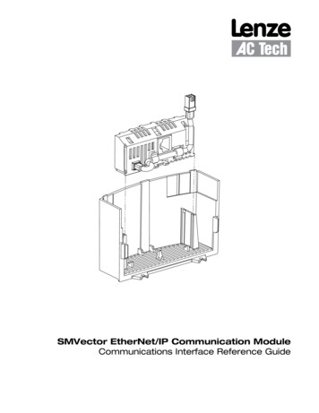
Installation3.2.7Example Networks3.2.7.1Single PC to Single SMVector DriveCrossover cableSMV DriveFigure 8: PC to SMV Drive3.2.7.2Single PC to Multiple SMVector Drives and Single SwitchSwitchNon crossover cable(Drives to Switch)Non crossover cable(PC to Switch)PC/LaptopSMV DrivesFigure 9: PC to Multiple SMV Drives3.2.7.3Single PC to Multiple SMVector Drives and Multiple Switches(Switch to Switch)Non crossover or crossover cable depends on switchSwitch 1Switch 2Non crossover cable(Drives to Switch)Non crossover cable(Drives to Switch)Non
from Lenze AC Tech Corporation. The information and technical data in this manual are subject to change without notice. Lenze AC Tech Corporation makes no warranty of any kind with respect to this material, including, but not limited to, the implied warranties of its merchantability and fitness for a given purpose. Lenze AC Tech Corporation