Transcription
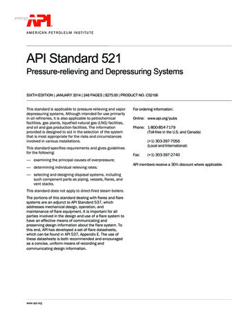
SPATIALANALYZER USER MANUALAutomated Precision (API)API Radian (Pro) & Radian (Plus)/OmniTrack2Figure 14-56. Radian & OT2Hardware SetupSet up the unit following the manufacturer’s directions. The API Radian and OmniTrack2 trackers are networked TCP/IP connected devicesand should be connected directly to a computer with an Ethernetcrossover cable or through a network switch.Connect the temperature probe and ensure that it is well clear of anyexternal heat sources (such as the heat fan on the back of the powersupply). Ensure that the instrument is powered on and that a reflectoris in the home position at startup.Software SetupEach version of SA is built with the most current version of the APIsoftware development kit (SDK). This driver set provides the tools tointerface with the instrument. Check the Readme file to see whichSDK version is being used. No additional software installation is necessary.Set the IP address on your computer to be compatible with the address set on the tracker. The default API IP address is: 192.168.0.168with the subnet mask 255.255.255.0.Starting the Interface1.446Select Instrument Add and choose API Radian or API OmniTrack2 from the Add Instrument to SA dialog (Figure 14-57).
CHAPTER 14 MEASURING WITH LASER TRACKERSFigure 14-57. Adding a Radiantracker.2.Run Interface Module without connecting (Instrument Run Interface Mode) and choose API Device Interface (do not use theLaser Trackers interface for either the Radian or the Omnitrack2).3.Within the Connect to SpatialAnalyzer dialog, select the instrument station (computer name, job name,Collection::Instrument Name: Serial Number) you wish toconnect your instrument to from the network list.4.In the API DI Connection dialog, enter t he tracker’s IP address(if different than the default) and use the Ping button to testthe connection if needed. Once satisfied, click OK. The nexttime you connect this instrument to the instrument, you canjust select Run Interface and Connect. This will utilize the lastsaved settings and automatically connect the instrument.Intelliprobe 360 and VProbePlease refer to the current API Intelliprobe 360 or V-probe user’s manual for setup and calibration instructions. A version is available onour webpage: Downloads/Laser%20Trackers/API/Radian/.447
SPATIALANALYZER USER MANUALFigure 14-58. Iprobe & VprobeNote: Conducting the Virtual Level measurement willtransform subsequent trackerdata. If you have taken measurements from this instrument station previously, a new instrumentstation must be added.1.Ensure the probe has been fully unpacked, configured tocommunicate with the controller, and calibrated within API’ssoftware. A *.prm file will be available with the I-probe andshould be placed in the C:\Analyzer Data\Persistence directory.2.Place a 1.5” inch reflector in the nest.3.Run a virtual level measurement (Check/Cal Virtual Level). Thiswill align the instrument with gravity, allowing the I-360 pendulum measurements to be correctly interpreted.4.Set up the probe tip and perform calibrations as necessary(Check/Cal Probe Offset )5.The Probe target should be detected and assigned automatically.6.Specific measurement profiles have been added for use witha probe and must be used to take data from the device (Figure 14-60). Start the measurement profile so that it is runningin the background and then use the probe to trigger measurements.Figure 14-59. Check/Cal Menu448
CHAPTER 14 MEASURING WITH LASER TRACKERSFigure 14-60. I-360 Measurement profiles.TTL MeasurementExternally triggered measurements are supported. This can be usefulfor synchronizing measurements with the operation of an additionaldevice or between multiple instruments. To do so:1.Double check that the ttl trigger source is plugged into thetrigger port on the controller2.Within the instrument interface go to Settings Tracker General Settings and hit API DI, in the tracker specific settingstoggle with the TTL Trigger On check box (Figure 14-61).The TTL trigger will take the place of your Sampling Frequency setting in any Temporal Scan acquisition until this option is un-checked.3.Select a scan measurement profile with a Temporal Scan Acquisition mode, such as Watch Update and start the measurement profile.4.Trigger measurements with the TTL signal.A point is acquired at each 5-0V transition of the input TTL signal,which should be connected directly to the instrument controller.Buffer control is also available for TTL triggered data. The buffer sizecan be set in the DI settings dialog and the buffer size is persisted(defaults to 200 pts.), but “TTL Trigger On” is turned off every time theinterface is closed. The buffer for TTL data will send its remaining contents to SA if you finish the measurement with “Done”, it will clear ifyou “Abort”.* Requires tracker firmware version 5.170 (or later).Figure 14-61. API TTL TriggerControls in the Tracker Settings.449
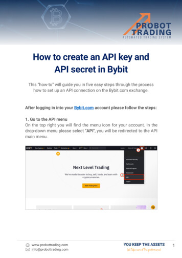
SPATIALANALYZER USER MANUALAPI T3The API T3 is a unique instrument in that it can be run with either of2 separate interfaces. To run the T3 with the API Device Interface follow the procedure outlined for the Radian. To take advantage of thelegacy interface follow the directions outlined below for connectionto the API T2 . The parameter file is stored on the controller for theAPI T3 tracker. Like the API T2 , you will see a default location for aparameter file. In the case of the T3, this is only the location where aback-up copy of the parameter file will be written from the controller. To change this location, just press the Browse button in the trackerconnection dialog.API T2 The parameter file, [tkr serial#].prm contains the kinematic correction info, home location, etc. for the tracker. For example, if yourtracker serial number is 3827, the file name will be 3827.prm. Thisfile must be located successfully by the tracker initialization for thetracker to run. By default the parameter file should be located in C:\Analyzer Data\Persistence. To change this location, just pressthe Browse button in the tracker connection dialog, as pictured in Figure 14-62.Figure 14-62. The legacy APIConnection window.The parameter file is edited when an API calibration is run. Ensure thatthe file attributes are NOT set to read only.You must have a working serial port for the connection to the tracker.Use the lowest available serial port number for the tracker connection.450
Analyzer Data\Persistence. To change this location, just press the Browse button in the tracker connection dialog, as pictured in Fig-ure 14-62. Figure 14-62. The legacy API Connection window. The parameter fi le is edited when an API calibration is run. Ensure that the fi le attributes are NOT set to read only.