Transcription
2141 ICON Way, Vacaville, CA 95688 ‐ Tel: 707.564.4000 – www.iconaircraft.comSERVICE BULLETINSB-041018 REV BDATE ISSUED:DATE EFFECTIVE:SUPERSEDES NOTICE:SUBJECT:6/14/20186/14/2018SB-041018-ARudder pedal brake master cylinder lower attachment bolt replacementand rod end inspectionAIRCRAFT AFFECTED:MODEL: ICON A5S/N: 00001-00020, 00022-00036Inspect all brake master cylinder rod ends for corrosion and replace ifnecessary, replace brake master cylinder lower attachment bolts andcarriage bolts with drilled head bolt for safety wiring.REQUIRED ACTION:TIME OF COMPLIANCE:REVISION NOTES:At or before the next service intervention, or regularly scheduledmaintenance event, but not to exceed the next one hundred (100)hours’ time-in-service from the effective date above.Rev B: Updated distance between both rod ends (center of rod end tocenter of rod end) S/N Effectivity:S/N: 00001-00020: 7.82 /- .05 inchesS/N: 00022-00036: 6.94 /- .05 inchesPURPOSE:ICON is committed to designing, manufacturing, delivering, and supporting a high quality Light SportAircraft, providing a level of safety well beyond expectations. A recently received service reportindicated that one of the brake master cylinder lower attachment bolts backed out and several otherbrake master cylinder lower bolts were found loose. This condition was only found on aircraft exposedto saltwater where the brake master cylinder rod ends were found corroded and seized. The purposeof this Service Bulletin is to provide instructions on replacing the brake master cylinder lower attachmentbolts with drilled head bolts that can be safety wired along with replacement of any corroded brakemaster cylinder rod ends.WARRANTY:ICON Certified Service Providers: Please submit an invoice for warranty reimbursement for labor andparts on completion of this service bulletin. Please reference service bulletin number SB-041018.1. 2-man hours of labor for disassembly, install of hardware, and reassembly.ICA009718-CPAGE 1 of 6
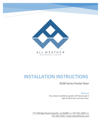
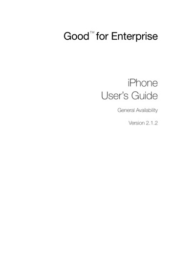
2141 ICON Way, Vacaville, CA 95688 ‐ Tel: 707.564.4000 – www.iconaircraft.comSERVICE BULLETINSB-041018 REV BPARTS LIST:Part NumberZM-001AN3CH3ANAS6703HU8MOLYKOTE G4700Loctite 243MS20995C32DescriptionRod end, BeringerBolt, MACH, CRES, 10-32X.063Bolt, MACH, CRES, 10-32X.500LubricantThread LockerSafety wire 0.032 in.QuantityA/N44A/NA/NA/NInstructions:Special tools, fixtures, or test equipment:1. Westward Needle nose grease fitting adapter Model number 13X058 or equivalent (shown inFigure 1)PREPARATION:1. It is permissible to disassemble the aircraft as required to permit accessibility, inspection,adjustment, maintenance, and repair in accordance with the latest release of the AircraftMaintenance Manual, ICA000833.2. Remove both forward and aft cockpit floors to gain access to the rudder pedal mechanisms.3. Remove both the LH and RH instrument panel tops.4. On Founders Edition aircraft (ASN00022 - beyond) it may make the job easier to remove theforward floor closeout panel by removing the attachment screw between the brake mastercylinders. Then temporarily slide the panel forward to reveal the brake master cylinder bolts.However, the operation can be completed without doing this.INSTALLATION:1. Inspect all brake master cylinder rod ends for corrosion. If corrosion is present replace the rodend with new by following the below procedure. An example of unacceptable corrosion is shownin Figure 2.2. If NO corrosion is present lubricate all brake master cylinder rod ends using a needle nose greasefitting adapter and Molykote G4700. Post lubrication, conduct lower attachment boltreplacement procedure below.Brake Master Cylinder Rod end replacement1. Remove both upper and lower brake master cylinder attachment bolts and retain hardware forre-installation2. Remove corroded rod ends and discard3. Replace corroded rod ends with new ZM-001 Rod ends. Lubricate the rod ends with MolykoteICA009718-CPAGE 2 of 6
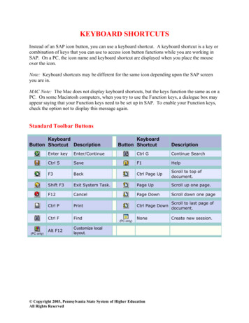
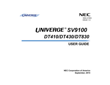
2141 ICON Way, Vacaville, CA 95688 ‐ Tel: 707.564.4000 – www.iconaircraft.comSERVICE BULLETINSB-041018 REV B4.5.6.7.8.G4700 using the needle nose grease fitting adapter special tool.Apply Loctite 243 to the new rod end threads prior to installation.Set the distance between both rod ends (center of rod end to center of rod end) to 6.94 /- 0.05inches for S/N: 00022-00036 or 7.82 /- 0.05 inches for S/N: 00001-00020.Lock jam nuts and torque to 40-50 in-lb.Reinstall brake pedal to brake master cylinder attachment bolt, washers, and bushings torqueto 20 in-lb.After complete, proceed to the brake master cylinder attachment bolt replacement procedurebelow:Brake master cylinder lower attachment bolt replacement.1. Remove the brake master cylinder lower bolts and discard, retain the washer and bushing.2. Install new brake master cylinder lower attachment bolt with NAS6703HU8 bolt, torque to 26in-lb as shown in figure 3 below.3. Remove lower forward rudder pedal mechanism carriage bolt as shown in figure 3.4. Install new lower forward rudder pedal mechanism carriage bolts with AN3CH3A, torqueto 26 in-lb.5. Safety wire the two bolts on each side together using 0.032” in safety wire as shown in Figure 4.6. Repeat steps 1-5 of this procedure for both sets of rudder pedals.7. Reassemble the aircraft.ICA009718-CPAGE 3 of 6
2141 ICON Way, Vacaville, CA 95688 ‐ Tel: 707.564.4000 – www.iconaircraft.comSERVICE BULLETINSB-041018 REV BFigure 1: Needle nose grease fitting adapter.Figure 2: Unacceptable Corrosion on rod end.ICA009718-CPAGE 4 of 6
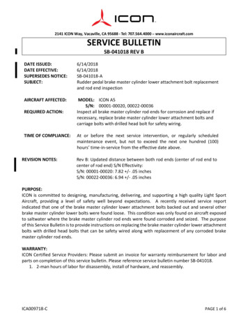
2141 ICON Way, Vacaville, CA 95688 ‐ Tel: 707.564.4000 – www.iconaircraft.comSERVICE BULLETINSB-041018 REV BNAS6703HU8AN3CH3ANAS6703HU8AN3CH3AForward floor closeout slid forwardFigure 3: Brake master cylinder and rudder pedal carriage bolts to be replaced. Founder’sEdition copilot rudder pedal design shown.ICA009718-CPAGE 5 of 6
2141 ICON Way, Vacaville, CA 95688 ‐ Tel: 707.564.4000 – www.iconaircraft.comSERVICE BULLETINSB-041018 REV BEnsure wire isn’t chafing onbottom of rod endFigure 4: Safety wire detail.VERIFICATION:1. Move the rudder pedals throughout the range of motion and ensure there is no binding inthe master cylinders.2. Actuate the brakes and ensure the pedals return freely.MAKE THE FOLLOWING LOGBOOK ENTRY:“Service Bulletin (insert subject bulletin number) has been complied with and installation is reported toICON Aircraft Customer Support and Service”.If you need assistance relocating your A5 to your home base or temporary storage arrangements, pleasecontact ICON Aircraft and ask for Customer Service and Support.If you are no longer in possession of this aircraft, please forward this information to the present owner/operator andnotify ICON Aircraft, Owners Center at:ICON Aircraft2141 ICON WayVacaville, CA 95688(855) FLY-ICON or (707) 564-4000support@iconaircraft.comPlease include the aircraft registration number, serial number, your name, and if known the contact information of thenew owner/operator.ICA009718-CPAGE 6 of 6
2141 ICON Way, Vacaville, CA 95688 ‐ Tel: 707.564.4000 – www.iconaircraft.comSERVICE BULLETINSERVICE BULLETIN APPROVALSB-041018 REV BBret DavenportNAMEFlight Sciences EConfidentiality Note: The information contained in this document is confidential. Any dissemination,distribution, or copy of this document, in whole or in part, is strictly prohibited without prior writtenauthorization by ICON Aircraft Inc.
2141 ICON Way, Vacaville, CA 95688 ‐ Tel: 707.564.4000 - www.iconaircraft.com SERVICE BULLETIN SB‐041018 REV B . ICA009718-C . PAGE 1 of 6. DATE ISSUED: 6/14/2018 DATE EFFECTIVE: 6/14/2018 SUPERSEDES NOTICE: SB-041018-A SUBJECT: Rudder pedal brake master cylinder lower attachment bolt replacement and rod end inspection