Transcription
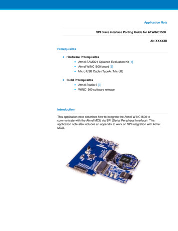
SPI -/I2C -Compatible, Temperature Sensor,4-Channel ADC and Quad Voltage Output DACEVAL-ADT7516FEATURESEasy evaluation of the ADT7516Can be used to emulate ADT7517 and ADT7519Evaluation software includedUSB interface to PCPowered from USB interfaceAPPLICATIONSThe two other parts in the family, the ADT7517 and ADT7519,differ only in that they have 10-bit and 8-bit DACs, respectively.The ADT7516 evaluation board can be used to emulate theADT7517 by setting the two LSBs of the DACs to zero and forthe ADT7519 by setting the four LSBs of the DACs to zero.The evaluation board allows all the input and output functionsof the ADT7516 to be exercised without the need for externalcomponents. The software allows control and monitoring of theADT7516’s internal registers.Portable battery-powered instrumentsPCsSmart battery chargersTelecommunications systemsElectronic test equipmentDomestic appliancesProcess controls The ADT7516 evaluation board data sheet on CD The ADT7516 evaluation boardINTRODUCTION Evaluation software on CD USB A to Mini-B cableThe ADT7516 evaluation board allows the ADT7516 digitaltemperature sensor, 4-channel ADC and quad DAC to bequickly and easily evaluated using a PC. Using the evaluationboard and its accompanying software, the ADT7516 evaluationboard can be interfaced to any PC running Windows XP,Windows 2000 or higher, via one of the computer’s USB ports.EVALUATION SYSTEM PACKAGE CONTENTSThe evaluation system package contains the following items:Rev. AEvaluation boards are only intended for device evaluation and not for production purposes.Evaluation boards as supplied “as is” and without warranties of any kind, express, implied, orstatutory including, but not limited to, any implied warranty of merchantability or fitness for aparticular purpose. No license is granted by implication or otherwise under any patents or otherintellectual property by application or use of evaluation boards. Information furnished by AnalogDevices is believed to be accurate and reliable. However, no responsibility is assumed by AnalogDevices for its use, nor for any infringements of patents or other rights of third parties that may resultfrom its use. Analog Devices reserves the right to change devices or specifications at any timewithout notice. Trademarks and registered trademarks are the property of their respective owners.Evaluation boards are not authorized to be used in life support devices or systems.One Technology Way, P.O. Box 9106, Norwood, MA 02062-9106, U.S.A.Tel: 781.329.4700www.analog.comFax: 781.461.3113 2007 Analog Devices, Inc. All rights reserved.
EVAL-ADT7516TABLE OF CONTENTSFeatures . 1AIN Analog Input Connector, P2 .3Applications. 1Test Points .3Introduction . 1Evaluation Board Software.4Evaluation System Package Contents. 1Installing the Software .4Revision History . 2Using the Software .5Evaluation Board Hardware . 3Evaluation Board Schematics and Artwork .9Using the Hardware. 3Ordering Information. 14Mini-B USB Connector, J1. 3Bill of Materials. 14DAC Output Connector, J2. 3Ordering Guide . 15VREF Input Connector, P1 . 3ESD Caution. 15REVISION HISTORY2/07—Revision A: Initial VersionRev. A Page 2 of 16
EVAL-ADT7516EVALUATION BOARD HARDWAREThe ADT7516/ADT7517/ADT7519 combine a 10-bittemperature-to-digital converter and a quad 12-/10-/8-bitDAC, respectively, in a 16-lead QSOP. This includes a bandgap temperature sensor and a 10-bit ADC to monitor anddigitize the temperature reading to a resolution of 0.25 C. TheADT7516/ ADT7517/ADT7519 operate from a single 2.7 V to5.5 V supply. The input voltage range on the ADC channels is0 V to 2.28 V, and the input bandwidth is dc. The reference forthe ADC channels is derived internally. The output voltage ofthe DAC ranges from 0 V to VDD, with an output voltage settlingtime of typically 7 ms.The ADT7516/ADT7517/ADT7519 provide two serial interface options, a 4-wire serial interface that is compatible withSPI, QSPI , MICROWIRE , and DSP interface standards and a2-wire SMBus/I2C interface. These products feature a standbymode that is controlled via the serial interface.The ADT7516 evaluation board contains the following maincomponents, which can be identified from the printed circuitboard (PCB) silkscreen and the schematic diagram (seeFigure 15 to Figure 19): ADT7516 IC, U9USB microcontroller, U1Interface buffers and analog switchesPower LED, D1Interrupt LED, D2Temperature Sensor, Q1Photo diode sensor, U14Bargraph driver and LED bargraph, U12/U8Connector for USB interface, J1DAC output connector, J2VREF input connector, P1AIN analog input connector, P2LDAC push-button, S1USING THE HARDWAREThe hardware is extremely simple to use. Before connecting theevaluation board to a USB port on the PC, using the USB A toMini-B cable provided, make sure the software is installed. Noexternal power supply is required.MINI-B USB CONNECTOR, J1The connections to J1 are shown in Table 1.Table 1. J1 ConnectionsJ1 Pin12345Mini-B Function5V Data DataKey (Not Used—Connected to Ground)GroundThe communication between the Mini-B plug and the rest ofthe evaluation board is handled by the USB microcontroller, U1.DAC OUTPUT CONNECTOR, J2The output of any one of the four DACs (selected by thesoftware) is available on this connector.VREF INPUT CONNECTOR, P1The architecture of one DAC channel consists of a resistorstring DAC followed by an output buffer amplifier. The reference voltage for the selected DAC is determined by the on-chipreference of 2.28 V or an external reference voltage, which maybe connected to P1.AIN ANALOG INPUT CONNECTOR, P2The ADT7516/ADT7517/ADT7519 offers four single-endedanalog input channels, which range from 0 V to 2.28 V, or0 V to VDD. This analog input may be connected using P1.TEST POINTSVarious system logic signals and the individual DAC outputsare available at the test points on the board.Rev. A Page 3 of 16
EVAL-ADT7516EVALUATION BOARD SOFTWAREThe software allows the ADT7516’s functions to be controlledfrom a PC via an easy-to-use interface operating under WindowsXP, Windows 2000, or higher. The contents of the device’sinternal registers can be easily read or altered through a userfriendly interface, while the Visual Display dialog box gives agraphical display of temperature and voltage and allows theovertemperature limit to be altered using a slider control.You are given the option of a Typical, Compact, or Custominstallation of the software. Select the desired option, then clickNext .If Custom is selected, a window appears allowing individualcomponents to be installed. Uncheck any components you do notwish to install, and click Next .If a Typical or Compact installation is selected, omit thisstep, and the Select Program Folder dialog box will appearimmediately. This allows you to select the program folder toadd program icons. Select the desired folder and click Next .INSTALLING THE SOFTWARETo install the software, insert the CD. Click Start Run, andenter X:ADT7516Eval.exe, where X is the letter of your CDdrive, and then click OK.InstallShield now installs the program files to the selectedfolders.Alternatively, run Windows Explorer or My Computer, selectthe CD drive, and double-click the ADT7516 v2.0.2.exe icon.Click Finish to complete the installation.The installer extracts the files needed to install the softwareand starts the InstallShield Wizard.If an existing version of the software is found during installation,you may modify the existing installation by adding or removingcomponents, repair the installation by replacing existing fileswith ones from the CD (useful if a file has been corrupted), oruninstall the entire software package.Select the desired option and click Next . If Modify is selected,you may add or remove components. If Repair is selected, all ofthe installed files are replaced with new files from the CD.04827-008If Remove is selected, a prompt appears to confirm the completeremoval of the software. Click OK to confirm removal of thesoftware. During removal of the software, you may need toconfirm removal of some files.Figure 1. InstallShield Wizard Startup ScreenClick Next to continue the installation. Various installationoptions are available, depending on whether a version of thesoftware is already installed. A license agreement appears ifthis is a completely new installation. Click Yes to accept theagreement and continue with the installation.These files may be used by other Analog Devices, Inc.’s software.If no other Analog Devices software is installed on the system,it is safe to delete the files. To remove all shared files withoutfurther prompting, check Don't display this message againbefore clicking Yes.Click Finish to complete the maintenance procedure.If you want to install the software in the default folder shown, clickNext . Otherwise, click Browse and choose a different folder.Select the folder in which to install the program and click OK.Rev. A Page 4 of 16
EVAL-ADT7516USING THE SOFTWAREWhen using the software, first ensure that the evaluation boardis connected to the USB port and the Power LED D1 is on.To start the software, click Start All Programs AnalogDevices ADT7516 Evaluation Software ADT7516Evaluation Software.INTERRUPTS AND LIMITS ICONThe software searches for the evaluation board and initializes it.GRAPH DISPLAY ICONDAC OUTPUT CONTROL ICONCONFIGURATION ICONDATA LOG ICON04827-011REGISTER TREE ICONFigure 4. Menu and Icon BarAt the top of the program window is a series of drop-downmenus and menu icons that can be used to access the variousfunctions of the software (see Figure 4 and the following list)or use the Settings menu to select these functions.Register Tree Icon: Displays a tree of the device registers.04827-009Configuration Icon: Allows the device to be configured.Figure 2. ADT7516 FoundIf the evaluation board is not found, the message in Figure 3appears. If this happens, check that the evaluation board iscorrectly connected, that D1 is lit, and then try again.Graph Display Icon: Displays graphs of temperature andvoltage. The View menu can also be used to select thesefunctions.DAC Output Control Icon: Allows the DAC outputs to beadjusted. The Settings menu can also be used to select thesefunctions.Interrupts and Limits Icon: Sets up interrupts and limits.04827-010Data Log Icon: Allows data to be logged and saved. The Filemenu can also be used.Figure 3. ADT7516 Not FoundMultiple windows for the previous software functions can beopen and active simultaneously. The Window menu showswhich window is on top and allows any window to be broughtto the front.ConfigurationClick the Configuration icon or use the Device menu to accessthe Configuration dialog box, which allows the ADT7517 to beset up. It consists of a set of four tabs that allow various functionsof the device to be configured.Rev. A Page 5 of 16
EVAL-ADT751604827-012and DAC B controlled by the external temperature sensor.The temperature corresponding to 0 V output can be set byadjusting the analog offset for each channel, and the resolutionfor the thermal voltage function can be set to 8 bits or 10 bits.04827-015Figure 5. Device OptionsThe Devices Options tab (see Figure 5) selects orenables/disables various options: Figure 7. LDAC OptionsMonitoringPower DownAveragingInterruptActive Low INT PolaritySPI InterfaceThe LDAC Options tab (see Figure 7) selects how the DACs areupdated. They can be updated manually from the LDAC pinby pressing S1, when the MSBs are written to one of the DACs(three different options are available), or from the LDACregister. If the LDAC register is selected, the buttons on theright of the dialog box are active and clicking on one of themupdates the corresponding DAC.Note that if the ADT7516 SPI interface is enabled, to switchback to I2C interface, it is necessary to exit the software, disconnect the board, and start again.04827-014The Pin AIN1 to Pin AIN3 are multiplexed and their operationcan also be toggled here.04827-013Figure 8. Reference OptionsFigure 6. DAC OptionsThe DAC Options tab (see Figure 6) selects the output rangefor each DAC (0 to VRef or 0 to 2 VRef). It allows the thermalvoltage function of the device to be configured, where theADT7516 operates as a temperature-to-voltage converter,with DAC A controlled by the on-chip temperature sensor,The Reference tab (see Figure 8) selects the internal 2.28 Vreference for DACs A and B and DACs C and D, or an externalreference connected to P1. If an external reference voltage isused, its value should be specified in the box provided. Thisallows the DAC value to be scaled correctly.Rev. A Page 6 of 16
EVAL-ADT7516Register Access04827-017Click the Register Tree icon or use the View menu to select theRegister Map Access window.04827-016Figure 10. Graphing WindowFigure 9. Register Map Access WindowThe Register Map Access dialog box (see Figure 9) allows thecontents of individual registers to be viewed, and those registersthat are read/write can have their contents changed. The windowon the left shows the registers arranged by function as a tree.The branches can be expanded or contracted by double clickingthe desired labels or the or symbols.The Graphing dialog box (see Figure 10) allows the internal orexternal temperature, VDD, the DAC outputs, or Pin AIN1 toPin AIN4 to be displayed as a rolling graph. Measurementlimits can also be displayed. To view the graphic data in moreor less detail, move the arrow pointers on the X- and Y-axes tozoom in or zoom out.DAC ControlClick the DAC Output Control icon or use the Device menu toaccess the DAC Control window (see Figure 11).The name of the register, its address, and its contents in hexadecimal, decimal, and binary are displayed. The register contentscan be read by clicking Read, or set to continuous reading bychecking the Continuous Read box. Those registers that areread/write can have their contents changed by clicking onindividual bits of the binary display to toggle them, or byentering a decimal or hexadecimal value in the Read and Writesection and clicking Write.Graphing04827-018Click the Graph Display icon or use the View menu to accessthe Graphing window (see Figure 10).Figure 11. DAC Control Dialog BoxThe DAC Control dialog box allows the individual DACs to becontrolled manually without having to manipulate the DACregisters directly. A DAC can be selected and controlled usingthe check boxes and the slider.Rev. A Page 7 of 16
EVAL-ADT7516The Logging/Save/Recall dialog box (see Figure 13) allows youto set which inputs are logged and the log interval. Once this isset up, the window in Figure 14 appears.Setting Interrupts and Limits04827-02104827-019Click the Interrupts and Limits icon or use the Device menuto access the Interrupt Settings dialog box (see Figure 12).Figure 12. Interrupt Settings Dialog BoxThe nine interrupt sources are shown on the left-hand side ofthe window. When an interrupt is asserted, correspondinggreen status indicator turns red. Interrupts can be masked bychecking the box next to the name of the interrupt source. Highand low limits for the measured parameters can be set using theslider controls.Data LoggingYou can use the Open window (see Figure 14) to open anexisting log file or create a new log file by typing in a new filename. After selecting an existing file or typing a new file name,click Open to begin data logging, and then click Start Logging.To stop data logging, click Stop Logging. Note that the Graphingfunction must be running during data logging or the data doesnot change.04827-020Click the Data Log icon or use the File menu to access theLogging/Save/Recall dialog box.Figure 14. Opening or Creating a Log FileFigure 13. Data/Save/Recall Dialog BoxRev. A Page 8 of 16
EVAL-ADT7516EVALUATION BOARD SCHEMATICS AND ARTWORK04827-001Figure 15. ADT7516 Evaluation Board Schematic Part 1Rev. A Page 9 of 16
EVAL-ADT751604827-002Figure 16. ADT7516 Evaluation Board Schematic Part 2Rev. A Page 10 of 16
EVAL-ADT751604827-003Figure 17. ADT7516 Evaluation Board Schematic Part 3Rev. A Page 11 of 16
EVAL-ADT751604827-004Figure 18. ADT7516 Evaluation Board Schematic Part 4Rev. A Page 12 of 16
EVAL-ADT751604827-005a04827-006Figure 19. ADT7516 Evaluation Board Silkscreen04827-007Figure 20. ADT7516 Evaluation Board PCB Layout (Component Side)Figure 21. ADT7516 Evaluation Board PCB Layout (Solder Side)Rev. A Page 13 of 16
EVAL-ADT7516ORDERING INFORMATIONBILL OF MATERIALSTable 2. Parts List for EVAL-ADT7516EB Evaluation BoardNameAIN1 to AIN3C1, C2C3C4C5 to C10, C12 to C16, C18, C19, C21 to C30C11C17C20D1D2J1J2P1P2Q1Q2R1R2, R4, R5, R11, R12, R15, R17, R21R3, R6R7, R20R13R14S1T1 to T7, T9 to T11T8, T12 to T15U1U2U3U4U5U6, U7U8U9U10, U11, U13U12U14VOUTA to VOUTDY1Part TypeTESTPOINTCAPCAP CAP CAPCAP CAPCAP 8013-CSPADP3303-3.324LC64ADG774TMP36ADG604LED BAR SValueTolerance22 pF47 μF2.2 μF0.1 μF10 μF1 μF10 μF0R10 kΩ100 kΩ1 kΩ1.2 kΩ3.9 kΩ1%1%1%1%1%1%24 MHzRev. A Page 14 of 16Part DescriptionRed testpoint50 V NPO SMD ceramic capacitor10 V SMD tantalum capacitor10 V SMD tantalum capacitor16 V X7R multilayer ceramic capacitor10 V SMD tantalum capacitor10 V DC Y5V ceramic capacitor10 V SMD tantalum capacitorLight emitting diode greenLight emitting diode redUSB Mini-B connector (usb-otg)2 pin terminal block (5 mm pitch)50 Ω SMB jack50 Ω SMB jackPNP bipolar transistorLow power bipolar transistorSMD resistorSMD resistorSMD resistorSMD resistorSMD resistorSMD resistorSMD push button switch (sealed 6 mm x 6 mm)Black testpointRed testpointUSB MicrocontrollerPrecision low dropout voltage regulator64 kΩ I2C serial EEPROMLow voltage quad SPDT switchLow voltage temperature sensorCMOS 4-channel multiplexerLED bar arrayFour channel ADC and quad voltage output DACDual SPST switchesIC driver dot bar display 20PLCCSensor, L/volts TSL250R TAOSRed testpointPlastic SMD crystal
EVAL-ADT7516ORDERING GUIDEModelEVAL-ADT7516EBESD CAUTIONDescriptionEvaluation BoardRev. A Page 15 of 16
EVAL-ADT7516NOTES 2007 Analog Devices, Inc. All rights reserved. Trademarks andregistered trademarks are the property of their respective owners.EB04827-0-2/07(A)Rev. A Page 16 of 16
If the evaluation board is not found, the message in Figure 3 appears. If this happens, check that the evaluation board is correctly connected, that D1 is lit, and then try again. 04827-010 Figure 3. ADT7516 Not Found 04827-011 INTERRUPTS AND LIMITS ICON DAC OUTPUT CONTROL ICON REGISTER TREE ICON GRAPH DISPLAY ICON CONFIGURATION ICON DATA LOG .