Transcription
INSTALLATION INSTRUCTIONS8100 Series Pocket DoorAbstractOur product installation guides will help you get itright the first time and every time.777 Aldridge Road Vacaville, Ca 95688 t: 707.452.1600 F:707.452.1616 www.allweatheraa.com
INSTALLATION INSTRUCTIONSINSTALLATION QUALITY CONTROLPERFORMING SPECIFIC QUALITY CONTROL PROCEDURES IS A CRITICAL PART OF COMPLETING ANY ALL WEATHERINSTALLATION. WE RECOMMEND THE INSTALLER FILL OUT THE QUALITY CONTROL SHEET AND FILE AS A RECORD OFCORRECT AND COMPLETE iving and Inspecting of Product Product was checked upon delivery at job site for correctness and was received as orderedProduct was checked and free of damageAny damage or incorrectness was reported immediately to All Weather or the dealer where the product waspurchasedProduct was stored in a dry safe place where it could avoid damageHardware box contents were checkedPre-Installation General Contractor or homeowner has been consulted prior to installation of productOpening is configured correctly and any squaring or level issues have been identifiedAppropriate size header has been verified for use in openingIf applicable, sill pan with Rear Leg (Back Dam) has been fabricated from appropriate material and locates correctly inthe depth of the rough openingOverhangs and other necessary design elements are present where appropriateLocal codes and practices are being adhered to regarding installation of productProblems pertaining to existing windows, doors and/or rough openings have been reported to responsible party andhave been resolved and documentedAll safety issues related to unsafe site conditions and hazardous materials have been properly addressed and resolved777 ALDRIDGE ROAD VACAVILLE, CA 95688 T: 707.452.1600 F: 707.452.1616 WWW.ALLWEATHERAA.COM1
INSTALLATION INSTRUCTIONSInstallation All installation materials used have been checked for compatibilityWeather resistant barrier and flashing were coordinated with contractor or authority on siteIf Swing Series, correct orientation of system has been identified. Inswing or Outswing.If Slider Series (including Stacking and Pocketing Series), location of operable and non-operable panels has beencheckedIf Bi-Fold Series, panel sequence has been checked from right to left, as seen from exteriorFrame has been sealed and joined at all points indicated in instructionsOpening checked for correct dimensionsFrame is installed at correct depth within the openingFrame has been installed square, level and plumbPlastic shims were utilized under sill when requiredJambs were shimmed to prevent rollingHead track installed with the appropriate crown over width of frameInstallation holes prepared correctlySealant was applied to sill installation holes prior to inserting screws & top of screw heads once appliedCorrect fastener placement has been followed as directed by manufacturerProper operation and adjustment has been achievedProduct was installed as directed by the ManufacturerFinal Check of Installation Frame has been checked for level, square and plumbAll horizontal and vertical adjustments have been made so that proper reveals are present and product is operating asdesignedWeep holes have been checked and free of obstruction and debrisAll trash has been discardedAll hardware has been installed correctly and checked for proper operationProduct has been closed and locked and recommended to not be used as thoroughfare by other trades.Product is protected from damageFinal inspection of weather proofing and operation has been performedJob has been turned over to contractor or other responsible party with approvalOtherIMPORTANTAll Weather recommends that installers return to site and perform a final check of installation. Namely that the headerhas not sagged under structure settlement and/or weight and necessary adjustments have been made prior toinstallation of exterior siding/stucco and interior finishes.Where applicable, each of the items checked above have been properly reviewed, verified and completed as part of my fieldquality control check prior to turning over the job to the responsible party/approving authority.Installer’s Signature:Date:777 ALDRIDGE ROAD VACAVILLE, CA 95688 T: 707.452.1600 F: 707.452.1616 WWW.ALLWEATHERAA.COM2
INSTALLATION INSTRUCTIONSTHANK YOU FOR PURCHASING FROM ALL WEATHER.ALL WEATHER INSTALLATION AND WARRANTY INFORMATIONTHE FOLLOWING INSTRUCTIONS ARE TO BE USED FOR ALL WEATHER ASSEMBLY AND INSTALLATION.LIMITED WARRANTY VARIES BASED ON JOB TYPE. A COPY THE LIMITED WARRANTY CAN BE FOUND ATallweatheraa.com/warranty. A COMPREHENSIVE CARE AND MAINTENANCE GUIDE CAN BE FOUND 2017/06/Care-Maintenance-Guide.pdf.FAILURE TO FOLLOW FACTORY ASSEMBLY, INSTALLATION AND MAINTENANCE INSTRUCTIONS WILL VOID THEMANUFACTURER’S LIMITED WARRANTY. ALL VISIBLE DEFECTS MUST BE REPORTED BEFORE INSTALLATION AND FINISHING.THESE INSTRUCTIONS ARE THE PROPERTY OF ALL WEATHER ARCHITECTURAL ALUMINUM AND MAY NOT BE DUPLICATED,ALTERED OR DISTRIBUTED FOR ANY PURPOSE WHATSOEVER WITHOUT THE EXPRESS WRITTEN PERMISSION OF ALL WEATHER.777 ALDRIDGE ROAD VACAVILLE, CA 95688 T: 707.452.1600 F: 707.452.1616 WWW.ALLWEATHERAA.COM3
INSTALLATION INSTRUCTIONSTHE MOST IMPORTANT CRITERIA FOR A SUCCESSFUL JOB ARE A SQUAREOPENING, A RIGID HEAD AND A CLEAN TRACK.IT IS RECOMMENDED THAT ALL WEATHER DOORS ARE INSTALLED WITH AT LEAST TWO PEOPLE; ONE PERSON HANDLING THEDOOR PANELS AND THE OTHER ATTACHING AND ADJUSTING HARDWARE.THE INSTALLATION OF YOUR DOOR SYSTEM REQUIRES THAT THE SILL, HEAD AND JAMBS ARE PERFECTLY STRAIGHT ANDSQUARE. IT IS RECOMMENDED THAT THE HEAD BE INSTALLED WITH A SLIGHT BOW UPWARD (AMOUNT SPECIFIED ININSTALLATION INSTRUCTIONS). THE SILL SHOULD BE INSTALLED FLAT AND STRAIGHT, ENSURING THAT THERE IS NO UPWARDBOWING. THE FRAME SHOULD BE CHECKED FOR SQUARE AND TWIST.ASSEMBLY SCREWS ARE PROVIDED BY ALL WEATHER. BE SURE TO CLEAN ANY METAL SHAVINGS FROM THE HEAD TRACK TOAVOID DAMAGE TO THE ROLLERS.ENSURING YOUR FRAME IS SQUARE, PLUMB, AND ATTACHED PROPERLY TO AN ADEQUATE HEADER WILL ALLEVIATE PROBLEMSIN THE FUTURE.INSTALLATION OF FLASHING TO ENSURE A PROPER WATER SEAL IS THE RESPONSIBILITY OF THE INSTALLER. LOCAL CODES ANDBUILDING PRACTICES SHOULD BE APPLIED.ALL WEATHER DOORS REQUIRE SILL PANS WITH REAR LEG (BACK DAM) AND RECOMMENDSCONSULTATION WITH A WATER PROOFING CONSULTANT FOR AN ADEQUATE DRAINAGE SYSTEM.* IMPORTANT NOTICE * READ PRIOR TO INSTALLATION.AN ALL WEATHER SYSTEM IS A SPECIALTY PRODUCT THAT YOU CANNOT ASSUME TO BE A STANDARD INSTALLATION OF ATYPICAL DOOR OR WINDOW.ALL WEATHER PRODUCTS SHOULD BE INSTALLED WITH OVERHEAD PROTECTION TO PREVENT THE EFFECTS OF SHEETINGWATER FROM ABOVE.WE RECOMMEND THAT A PROFESSIONAL WATERPROOFING CONSULTANT BE USED TO PROPERLY INTEGRATE OUR PRODUCTSINTO THE WEATHER BARRIER OF THE WALL STRUCTURE.777 ALDRIDGE ROAD VACAVILLE, CA 95688 T: 707.452.1600 F: 707.452.1616 WWW.ALLWEATHERAA.COM4
INSTALLATION INSTRUCTIONSProvided Assembly Fasteners &PartsPart12PictureDescription#10-12 x 3" Square Drive PanHead Grade 18-8 Type A PointStainless Steel Sheet MetalScrew#8-15 x 1-1/2" Square Drive PanHead Grade 18-8 Type A PointStainless Steel Sheet MetalScrewPurposeTo secure the keeper onto the doorjamb and building frame through 4slotted holes.To fasten the door frame componentstogether. 8 per track will be needed.3.18" x 12" Black Rigid PVC TrackClipTo Connect multiple Head and SillAssemblies together via the Frameconnecting grooves.43mm x 30mm Spring Roll PinTo Connect multiple Head and SillAssemblies together via the Screwholes.5Black PLA Roller TrackConnectorTo Connect multiple Head and SillAssemblies together via the Frameroller track grooves.62" x 1.6" Head TrackTo guide the sliding panel, top memberof door frame.72" x 1.1" Jamb TrackFrame member. To collect panels andprovide a seal for panels when in theclosed position. The keeper will bemounted on the inside of the jamb.82" x .75" Sill TrackFrame sill member. To provived aweight bearing member and track forthe panel rollers to travel on.777 ALDRIDGE ROAD VACAVILLE, CA 95688 T: 707.452.1600 F: 707.452.1616 WWW.ALLWEATHERAA.COM5
INSTALLATION INSTRUCTIONS93.1" x 1.3" Pocket Wall ProfileThis part mounts to the pocket openingon both sides. It provides a location forthe pocket interlock to be mounted. Italso features a stucco return.102.2" x .4" Pocket InterlockPrevents pocket panel from bypassingthe pocket. Provides a seal for the doorwhen closed.11.5" x .3" Weather Strip HolderThis part connects to the pocketinterlock to provide a seal when thepocket panel is in the closed position.12KeeperTo provide the panel hooks on an activepanel channels to lock into, to keep thepanel secured into the frame.131.8" x 1.6" Trim CapTo cover and protect the track pocketson the jambs that will not be used bythe panels.14.4" x .6" ThresholdTo cover and protect the track pocketson the sills that will not be used by thepanels.15Pocket Closure Plate(Aluminum, size varies basedon door)This part mounts to the pocket panel onthe jamb that travels inside of thepocket. It hides the internal frame andkeeps items from going into the pocketin the closed position.16Pocket Closure Support Bracket(Aluminum, size varies basedon door)To support and provide rigidity to to thepocket closure plate. One will beneeded at the top, middle, and bottomof each pocket closure plate.777 ALDRIDGE ROAD VACAVILLE, CA 95688 T: 707.452.1600 F: 707.452.1616 WWW.ALLWEATHERAA.COM6
INSTALLATION INSTRUCTIONS17*Head Track End Cap (*forstaggered track doors only)Designed for aesthetic purposes tocover the exposed head track faces inthe location the staggered tracksterminate.18*Sill Track End Cap (*forstaggered track doors only)Designed for aesthetic purposes tocover the exposed sill track faces in thelocation the staggered tracks terminate.19*10 x 1” Phillips Drive Flat HeadSelf Drilling Screw (*forstaggered track doors only)To fasten the track end caps to theexposed track faces.777 ALDRIDGE ROAD VACAVILLE, CA 95688 T: 707.452.1600 F: 707.452.1616 WWW.ALLWEATHERAA.COM7
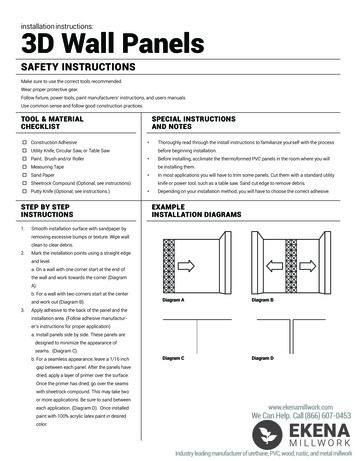
INSTALLATION INSTRUCTIONSNote: Openingshould be flashed with the appropriate flashing material to meet industrystandards. Please refer to Federal Specification UU-B-790a and AAMA 2400-02.Disclaimer: Eachinstallation job has its unique set of challenges and circumstances. Because ofthat, the provided set of installation instructions for All Weather Architectural Aluminumproducts is meant only to serve as a set of standardized guidelines and NOT necessarily a strictmanual to follow regardless of situation.As a professional, it is incumbent upon you and your team to identify instances that do not alignwith the Installation instruction requirements. All installations must comply with AAMAspecifications.Accordingly, All Weather does not assume responsibility, and disclaims liability for damage, loss,or expense arising from improper use or application of these installation instructions.Frame Installation1. The pocket should be open on at least one side until after the door installation is complete.2. Verify that the rough opening is the correct size to assure the door will fit in the opening.3. Check to ensure that the floor where the door will be installed is level. If the floor is not leveland varies more than 1/16” per foot or a total of 1/4” over the entire width of the opening,correct the floor prior to installation.4. Remove the frame components from its packaging and lay it out in front of the opening.5. For doors with multiple tracks, attach adjacent heads, sills, and jambs using track clips (Part #3).Figure 1 shows the junction of three sills via track clips. Track clips can be pressed or hammeredinto place.Sill Part #8Figure 1Track Clips Part #3777 ALDRIDGE ROAD VACAVILLE, CA 95688 T: 707.452.1600 F: 707.452.1616 WWW.ALLWEATHERAA.COM8
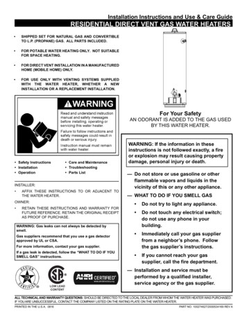
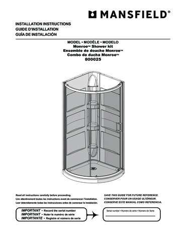
INSTALLATION INSTRUCTIONS6. Splicing is required for doors wider than extrusion stock length. If splicing is required, consultFigures 2a-3b. To splice the sill (Figure 2a), insert roll pins (Part #4) halfway into screw channels.Coat track connectors (Part #5) in sealant (Sealant should conform to AAMA 802.3-16 and 803.316) and slide halfway into metal track. Cover cross-sectional face with sealant as shown in Figure2b and join the components by sliding one track into the other. For multiple track doors (such asFigures 2a and 2b), ensure that track clip (Part #3) crosses over the splice. Lastly, fasten a pieceof appropriately sized sheet metal over the junction using sealant. Sheet metal width variesbased on number of tracks (consult figures 2b, 3b), and length should be double the width.Sill Part #8Track Connector Part #5 (x2)*Sealant required onconnector*Figure 2bRoll Pin Part #4 (x4)Figure 2aSheet MetalTrack Clip Part #3Note: given part quantities are basedon the two-track assembly pictured inFigure 2. Assemblies may includemore/less components.7. To splice the head (Figure 3a), insert roll pins (Part #4) into the head screw channels. Coat theentire cross section in sealant as shown in figure 3b, join components, and ensure track clip(Part #3) crosses over the splice (if multiple track door). Lastly, attach a piece of sheet metalover the junction using sealant.Sheet MetalRoll Pin Part #4 (x4)Figure 3bTrack Clip Part #3Figure 3aHead Part #6777 ALDRIDGE ROAD VACAVILLE, CA 95688 T: 707.452.1600 F: 707.452.1616 WWW.ALLWEATHERAA.COM9
INSTALLATION INSTRUCTIONS8. Prepare frame by applying compatible sealant around the perimeter of both ends of the framehead (Part #6) and sill (Part #8). Use the screws (Part #2) provided in the hardware box (Usesealant to lubricate screws) and assemble the frame as shown in figures 4a, 4b, and 4c.Screws Part #2Figure 4cHead Part #6Screws Part #2Jamb Part #7Figure 4aSill Part #8Figure 4bScrews Part #2777 ALDRIDGE ROAD VACAVILLE, CA 95688 T: 707.452.1600 F: 707.452.1616 WWW.ALLWEATHERAA.COM10
INSTALLATION INSTRUCTIONS9. Prepare rough opening by checking diagonal dimension of opening to verify square and applywater resistant barrier as shown in figure 5a. Use steps A through C for applying waterresistance barrier. Use step D for installation of sill pan.A. 12” Sill Wrap (3” wrapped into opening); Overlaps where sill Self-Adhering Sheet Membrane(SASM) will be by 1” (Self-adhered flashing is optional)B. 12” Jamb SASM (3” wrapped into opening), overlaps Sill SASM by 1” and runs 2” beyondheader openingC. 6” Header Wrap (3” wrapped into opening), overlaps jamb SASM by 1”D. (Sill pan is recommended on all door installs) Apply a 3/8” bead of sealant around theperimeter of the bottom side of the sill pan as shown in figure 5b (Sealant should conformto AAMA 802.3-16 and 803.3-16). Apply glue on the sill in the opening to secure the sill pan.Figure 5aFigure 5bNote: Leave 2” gaps oneither ends on the exteriorside of the sill pan to allowwater to weep out.10. Make sure that each corner joint of the frame has sufficient sealant. Apply additional sealant tothe corner joints as necessary to ensure a watertight seal as shown in figure 6.Head Part #6Jamb Part #7Figure 6777 ALDRIDGE ROAD VACAVILLE, CA 95688 T: 707.452.1600 F: 707.452.1616 WWW.ALLWEATHERAA.COM11
INSTALLATION INSTRUCTIONS11. Apply a continuous bead of sealant across the entire sill of the opening and pocket where thedoor frame will sit, including a bead of sealant between the sill pan and frame on the interiorside as shown in figure 7a, then insert door frame into the opening and pocket as shown infigure 7b. (Sealant should conform to AAMA 802.3-16 and 803.3-16). After frame is installed,seal all 4 corners per detail 7b and 7c. Make sure the exterior and weeps are not covered withsealant to allow water in the tracks to weep out. Install screws where there are shims on the sill.Install ScrewSealantSill panShimsFigure 7bFigure 7aFigure 7c12. Secure door frame to the opening using appropriate fasteners. Install screws as shown in figure8a; spacing to be as shown in figure 8b where A 12” and B 3”. Cross measure and use shimsas necessary to adjust the door frame so that the door frame is plumb, level and square. Seal allthe fasteners with compatible sealant.Head Part #6Figure 8aFigure 8bJamb Part #7777 ALDRIDGE ROAD VACAVILLE, CA 95688 T: 707.452.1600 F: 707.452.1616 WWW.ALLWEATHERAA.COM12
INSTALLATION INSTRUCTIONS13. Apply backer rod and compatible sealant to the interior joint between the frame and the roughopening as shown in Figures 9a and 9b.Figure 9aFigure 9bPanel Installation14. In order to keep the rollers from interfering with the sill during installation, it is recommendedto temporarily fasten a piece of string around the bottom of the panel inside the roller cavity, asshown in Figure 10a. The string should have enough tension to hold the rollers upright.Figure 10a777 ALDRIDGE ROAD VACAVILLE, CA 95688 T: 707.452.1600 F: 707.452.1616 WWW.ALLWEATHERAA.COM13
INSTALLATION INSTRUCTIONS15. If you have a staggered track door, you will need to temporarily remove the head and sill trackend caps (Part #17, #18) to avoid clearance issues. For info on removing and installing staggeredtrack end caps, consult Appendix A. Install the interior panel into the second closest track andslide it into the pocket halfway. Once in position, move panel to the interior track. Then installremaining panels so that the interlocks overlap correctly, per figures 10b and 10c. Use a puttyknife if necessary to lift rollers over the roller track. Once in place, remove the string from underthe rollers.Figure 10bFigure 10c16. Once all panels are installed, affix pocket closure plate (Part #15) and pocket closure supportbrackets (Part #16) to the pocket panel as shown in figure 11b. The pocket closure plate runs thespan of the pocket panel, while the pocket closure support brackets should be positioned at thetop, middle, and bottom of the panel. Use #8 x 1" self-drilling screws every 12 inches down thejamb of the pocket closure plate and use 3 screws through each pocket closure support bracket.Holes on the pocket closure support bracket should be pre-drilled to 1/8” and positioned asshown in figure 11a.Pocket Closure SupportBracket Part #16Pocket Closure Plate Part #15Figure 11aInstall Screws777 ALDRIDGE ROAD VACAVILLE, CA 95688 T: 707.452.1600 F: 707.452.1616 WWW.ALLWEATHERAA.COMFigure 11b14
INSTALLATION INSTRUCTIONS17. Once the frame is installed, install the Pocket Wall Profiles (Part #9) leaving a 1/4" gap betweenthe frame and the pocket wall profile with the pocket interlock (Part #10) as shown in figure12b. Install screws through the screw races to secure the pocket wall profile. Screws should bespaced every 18". Once the pocket wall profiles have been installed, install the pocket panel andmake roller adjustments for smooth operation.1. After the rollers have been adjusted, push the panel into the pocket and install thepocket interlock (Part #10) by snapping in starting with inserting the side with the hook.2. Next, press the pocket interlock (Part #10) in place as shown in figure 12a.3. Lastly, press the weather strip holder (Part #11) into the pocket interlock.InstallScrewWeather StripHolder Part #11Install ScrewPocket WallProfile Part #9Pocket Interlock Part #10Install ScrewInstall ScrewFigure 12aFigure 12bIf the pocket panel needs to be removed, pull the weather strip holder off the pocket interlockand remove the pocket interlock with a flathead screwdriver as shown in figure 12c startingfrom the top or bottom.Weather Strip Holder Part #11Pocket Interlock Part #10Figure 12cPocket Wall Profile Part #9777 ALDRIDGE ROAD VACAVILLE, CA 95688 T: 707.452.1600 F: 707.452.1616 WWW.ALLWEATHERAA.COM15
INSTALLATION INSTRUCTIONS18. Temporarily adjust the panel upward by lifting the panel and turning the adjustment screwshown in figure 13a clockwise as shown in figure 13b until the rollers regain contact with thetrack. It is important to physically lift the panel while adusting upward so that the adjustmentscrew does not strip due to the weight of the panel. Adjust the rollers of the active panels byturning the adjustment screw shown in figure 13a to achieve proper alignment of the doorpanels (it is easier to adjust down than up). Turn screw clockwise to raise the panel andcounterclockwise to lower the panel as shown in figure 13b.Figure 13bFigure 13a19. After the final roller adjustments, install the keeper (Part #12) into the lock side jamb (Part #7)by aligning with the lockset hooks on the panel and marking the location of the keeper’s fourscrew holes onto the jamb. Next, pre-drill holes in the jamb at the marked locations using a 1/8”- 3/16” drill bit. Lastly, fasten the keeper to the jamb with screws (Part #1) as shown in figure14a (use sealant to lubricate screws). After the keeper has been installed, adjust the throw onthe hooks of the lockset to ensure a tight fit when the door is closed and locked by turning theadjustment screw located between the hooks shown in figure 14b.Mark Location, Pre-Drill, Fastento Jamb with Screws Part #1Keeper Part #12Lockset HooksFigure 14aMark Location, Pre-Drill, Fastento Jamb with Screws Part #1Figure 14b777 ALDRIDGE ROAD VACAVILLE, CA 95688 T: 707.452.1600 F: 707.452.1616 WWW.ALLWEATHERAA.COM16
INSTALLATION INSTRUCTIONSTrim Cap InstallationFor PX and XP Door20. Take the longest trim cap pieces (Part #13) and install into the exterior jamb track (Part #7) ofthe operable side shown in figure 15a and interior jamb track of the fixed side as shown in figure15b.Trim Cap Part #13Trim Cap Part #13Figure 15aFigure 15b21. Install the threshold (Part #14) into the exterior sill track (Part #8) and install the smallest trimcap (Part #13) into the head exterior track (Part #6) shown in figures 16a and 16b.Trim Cap Part #13Threshold Part #14Figure 16aFigure 16b777 ALDRIDGE ROAD VACAVILLE, CA 95688 T: 707.452.1600 F: 707.452.1616 WWW.ALLWEATHERAA.COM17
INSTALLATION INSTRUCTIONSFor PXXP Door22. Install thresholds (Part #14) into the exterior sill track (Part #8) shown in figure 17a then installthe trim cap that is the same length as the threshold into the exterior head track (Part #6)shown in figure 17b.Trim Cap Part #13Threshold Part #14Figure 17bFigure 17aFor PXX or XXP Door23. Install the longest trim cap pieces (Part #13) into the exterior and center jamb tracks (Part #7)on the operable side as shown in figure 18a then install the other two trim caps that are thesame length into the interior and center jamb tracks shown in figure 18b.Trim Cap Part #13Trim Cap Part #13Trim Cap Part #13Trim Cap Part #13Figure 18aFigure 18b777 ALDRIDGE ROAD VACAVILLE, CA 95688 T: 707.452.1600 F: 707.452.1616 WWW.ALLWEATHERAA.COM18
INSTALLATION INSTRUCTIONS24. Install thresholds (Part #14) into the exterior and center sill tracks (Part #8) shown in figure 19aand the trim cap (Part # 13) of the same length into the exterior and center head tracks (Part #6)shown in figure 19b.Threshold Part #14Figure 19aTrim Cap Part #13Figure 19b777 ALDRIDGE ROAD VACAVILLE, CA 95688 T: 707.452.1600 F: 707.452.1616 WWW.ALLWEATHERAA.COM19
INSTALLATION INSTRUCTIONSAppendix A: Track End Cap Removal and Installation (For Staggered Track Doors Only)For staggered track doors only, assemblies come with sill and head track end caps attached (Part #17,#18). These are designed for aesthetic purposes to cover the exposed head and sill track faces in thelocation the staggered tracks terminate. To remove the end caps for panel installation, simply unscrewthe screws (Part #19) from the head or sill screw channels and remove the caps. When reattaching afterpanel installation, the track faces should be coated in sealant, and the end cap screwed back onto theface via screw channels as shown in Figures 20a and 20b.Screws Part #19Sill Track End Cap Part #18Figure 20aHead Track End Cap Part #17777 ALDRIDGE ROAD VACAVILLE, CA 95688 T: 707.452.1600 F: 707.452.1616 WWW.ALLWEATHERAA.COMFigure 20b20
8100 Series Pocket Door 777 Aldridge Road Vacaville, Ca 95688 t: 707.452.1600 F: 707.452.1616 www.allweatheraa.com Abstract Our product installation guides will help you get it right the first time and every time. 777 ALDRIDGE ROAD VACAVILLE, CA 95688 T: 707.452.1600 F: 707.452.1616 WWW.ALLWEATHERAA.COM 1