Transcription
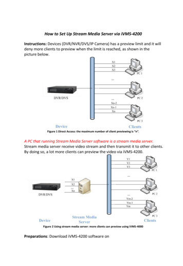
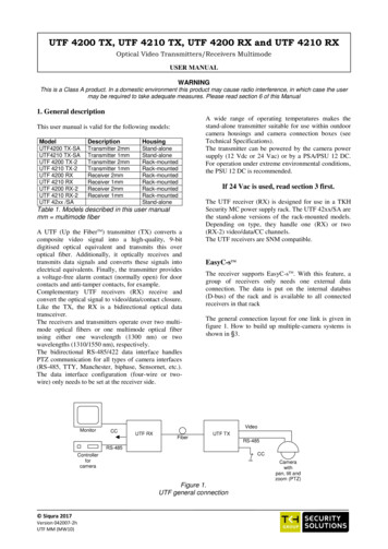
UTF 4200 TX, UTF 4210 TX, UTF 4200 RX and UTF 4210 RXOptical Video Transmitters/Receivers MultimodeUSER MANUALWARNINGThis is a Class A product. In a domestic environment this product may cause radio interference, in which case the usermay be required to take adequate measures. Please read section 6 of this Manual1. General descriptionThis user manual is valid for the following models:ModelDescriptionHousingUTF4200 TX-SAUTF4210 TX-SAUTF 4200 TX-2UTF 4210 TX-2UTF 4200 RXUTF 4210 RXUTF 4200 RX-2UTF 4210 RX-2UTF 42xx /SATransmitter 2mmTransmitter 1mmTransmitter 2mmTransmitter 1mmReceiver 2mmReceiver 1mmReceiver 2mmReceiver nd-aloneTable 1. Models described in this user manualmm multimode fiberA UTF (Up the FiberTM) transmitter (TX) converts acomposite video signal into a high-quality, 9-bitdigitised optical equivalent and transmits this overoptical fiber. Additionally, it optically receives andtransmits data signals and converts these signals intoelectrical equivalents. Finally, the transmitter providesa voltage-free alarm contact (normally open) for doorcontacts and anti-tamper contacts, for example.Complementary UTF receivers (RX) receive andconvert the optical signal to video/data/contact closure.Like the TX, the RX is a bidirectional optical datatransceiver.The receivers and transmitters operate over two multimode optical fibers or one multimode optical fiberusing either one wavelength (1300 nm) or twowavelengths (1310/1550 nm), respectively.The bidirectional RS-485/422 data interface handlesPTZ communication for all types of camera interfaces(RS-485, TTY, Manchester, biphase, Sensornet, etc.).The data interface configuration (four-wire or twowire) only needs to be set at the receiver side.MonitorCCA wide range of operating temperatures makes thestand-alone transmitter suitable for use within outdoorcamera housings and camera connection boxes (seeTechnical Specifications).The transmitter can be powered by the camera powersupply (12 Vdc or 24 Vac) or by a PSA/PSU 12 DC.For operation under extreme environmental conditions,the PSU 12 DC is recommended.If 24 Vac is used, read section 3 first.The UTF receiver (RX) is designed for use in a TKHSecurity MC power supply rack. The UTF 42xx/SA arethe stand-alone versions of the rack-mounted models.Depending on type, they handle one (RX) or two(RX-2) video/data/CC channels.The UTF receivers are SNM compatible.EasyC-sTMThe receiver supports EasyC-sTM. With this feature, agroup of receivers only needs one external dataconnection. The data is put on the internal databus(D-bus) of the rack and is available to all connectedreceivers in that rackThe general connection layout for one link is given infigure 1. How to build up multiple-camera systems isshown in §3.VideoUTF RXFiberUTF TXRS-485RS-485CCControllerforcameraCamerawithpan, tilt andzoom (PTZ)Figure 1.UTF general connection Siqura 2017Version 042007-2hUTF MM (MW10)
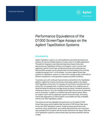
Transmitter2. Indicators and connectorsThe miniature stand-alone UTF transmitter has thefollowing indicators and connectors (figure 2):1:12:3:4:5:253The rack-mounted UTF transmitter has the followingindicators and connections (figure 3):41:Figure 2.Indications and connectors on the miniature UTFtransmitter (stand-alone)2:3:4:5:121255636:7:63The UTF receiver has the following indicators andconnections (figure 4):1: SYNC: This LED can show: Green: Operational link; Red: Local synchronisation error; Yellow: Remote synchronisation error.2: BNC 75 Ω connector: Composite video output3: TX: Connection for optical fiber (one/two fibermodels)RX: Connection for optical fiber (two-fibermodels)4: Dual toggle switches for 4-/2-wire RS485 data andD-Bus operation (EasyC-s)5: NV: This LED can show:- Red: No video on in- or output;- Off: Video signal present.6: 6-Pin data connector4-Pin connector for potential-free alarm contacts(channel CC1 and channel CC2).776353112Figure 3.Indications andconnections on theUTF transmitter5SYNC: this LED can show: Green: Operational link; Red: Local synchronisation error; Yellow: Remote synchronisation error.BNC 75 Ω connector: Composite video outputTX: Connection for optical fiber (one/two-fibermodels)RX: Connection for optical fiber (two-fibermodels)Not usedNV: This LED can show: Red: No video on in- or output; Off: Video signal present.6-Pin data connector4-Pin connector for potential-free alarm contacts(channel CC1/GND and channel CC2/GND).Receiver46TX: Optical fiber connection (one/two-fibermodels)RX: Optical fiber connection (two-fiber models)7-Pin data connector2-Pin power supply connectorBNC 75 Ω connector composite video inputSYNC: This indicator can show: Green: Operational link; Red: Local synchronisation error; Yellow: Remote synchronisation error.2Figure 4.Indications andconnections on theUTF receiver2
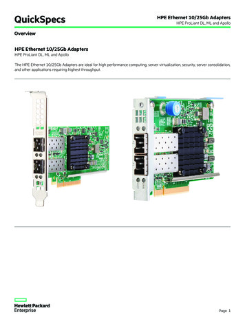
2-wire mode:3. Configuration and installation! Note on powering of a UTF TX-MSA with 24 Vacfrom the camera !Data input termination and/or line biasingon the UTF input are provided with the unit.UTF TX or RXRS-485 connectionThe miniature stand-alone transmitter can convert 24Vac power through an internal full rectifier bridge; the"-" of its internal DC voltage is connected to the metalhousing. If the camera uses the same Vac power supplyin parallel, but with a single-sided rectifier circuit, theUTF power supply diodes may suffer, since there willalways be a connection between the housings throughthe coax cable shielding. To prevent the occurrence ofsuch problems, proper measures must be taken toseparate the two loads of the 24 Vac supply; this mightbe preferable in any case, as a precaution.If in doubt, please contact your distributor.Controller or cameraRS-485 connectionVcc10kRX-120DATA IN/OUTRX 10kGNDTX-During 2-wire operation, TX lines will bedisconnected and output data is sentthrough the RX linesTX MountingBefore mounting the miniature transmitter, themounting bracket has to be installed in a suitable place.After securing the bracket, the transmitter can beclicked into it. Make sure the transmitter is positionedand fixed correctly.A stand-alone receiver can be installed nearlyeverywhere. When more than one receiver is needed,use TKH Security MC 10 and MC 11 cabinets.Figure 6.2-Wire connectionTermination and bias resistorsWhen connecting more than one UTF in a front-panelbus structure, only one data input on the UTF modulesneeds to be terminated and/or biased. The resistors canbe attached to the external connectors. Whether theyare needed depends on the termination and biasresistors in the camera, etc.RS-485/422 connectionBefore connecting the system, the RS-485 connectionneeds to be configured for 2-wire or 4-wire mode. Thiscan be done with the upper switch (2W - 4W, seefigure 4 pos. 4) on the front panel of the receiver. Thepositions are indicated on the front panel.The connections between the transmitter camera,and receiver controller in 4-wire and in 2-wire modeare indicated in figures 5 and 6, respectively.UTF RXUTF RXUTF RXUTF RX4-wire mode:Data input termination and/or line biasing resistorson the UTF input are provided with the unit.UTF TX or RXRS-485 connectionPTZCONTROLController or cameraRS-485 connectionVccFigure 7.Termination and bias example, front panel busconfiguration10kRX-120DATA OUTRX NO TERMINATION/BIAS RESISTORS HERE EasyC-sTM10kWith the lower switch (D-bus, see figure 4 pos. 4) inthe "ON" position, the external data going into the datainput (see figure 4 pos. 6) is put onto an internal databus in the cabinet, while a UTF receiver is then alsoenabled to get data from this internal data bus. Tominimise external wiring, the UTF models are fittedwith EasyC-sTM.GNDTX--DATA INTX Data input termination and/or line biasingshould be inside the controller or cameraFigure 5. 4-Wire connection3
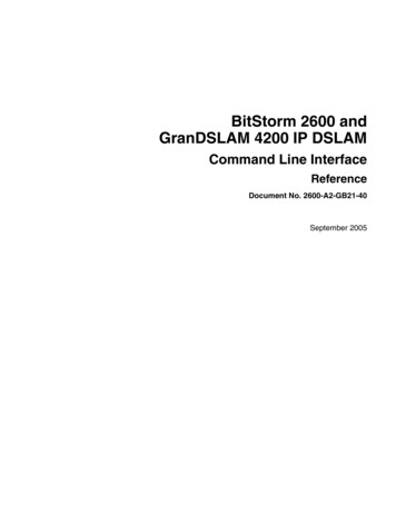
To be able to control a group of receivers with oneexternal data connection, the lower switch has to be inthe "ON" position for each receiver belonging to thatgroup and the external data has to be connected to onlyone receiver of that group.The single RS-485/422 data link in the lowest UTF RX(figure 8) needs no termination resistors.Internal data busDataMC 11 CABINETVideoUTF RXFiberUTF TXVideoVideoUTF RXVideoUTF RXFiberFiberUTF TXUTF TXData (e.g.PTZ)Figure 8.Data link in lowest UTF RXPowering up a systemWhen powering up a system, the "SYNC" indicator onthe transmitter should show green and the "SYNC"indicator on the receiver should also light up green.When no video signal is present, the "NV" indicatorsshow red.4. Care and maintenanceThe modules are designed to be maintenance free. Toguarantee reliable operation of the unit, take thefollowing precautions: prevent dust from collecting on or in theequipment; protect the equipment against moisture; maintain cooling space around the equipment.4
EMC5. Technical specificationsWarning: Operation of this equipment in a residentialenvironment could cause radio interference.This device has been tested and found to meet the CEregulations relating to EMC and complies with the limits for aClass A device, pursuant to Part 15 of the FCC rules.Operation is subject to the following two conditions: (1) Thisdevice may not cause harmful interference, and (2) This devicemust accept any interference received, including interference thatmay cause undesired operation. These limits are designed toprovide reasonable protection against interference to radiocommunications in any installation. The equipment generates,uses, and can radiate radio frequency energy; improper use orspecial circumstances may cause interference to other equipmentor a performance decrease due to interference radiated by otherequipment. In such cases, the user will have to take appropriatemeasures to reduce such interactions between this and otherequipment.For technical specifications, refer to the data sheet ofthe relevant model.6. Safety, EMC, ESDGeneralThe safety information contained in this section, and on otherpages of this manual, must be observed whenever this unit isoperated, serviced, or repaired. Failure to comply with anyprecaution, warning, or instruction noted in the manual is inviolation of the standards of design, manufacture, and intendeduse of the unit.Installation, adjustment, maintenance and repair of thisequipment are to be performed by trained personnel aware of thehazards involved. For correct and safe use of the equipment andin order to keep the equipment in a safe condition, it is essentialthat both operating and servicing personnel follow standard safetyprocedures in addition to the safety precautions and warningsspecified in this manual, and that this unit be installed in locationsaccessible to trained service personnel only.Siqura assumes no liability for the customer’s failure to complywith any of these safety requirements.Note that the warning above does not apply to TKH Securityproducts which comply with the limits for a Class B device. Forproduct-specific details, refer to the EU Declaration ofConformity.Any interruption of the shielding inside or outside the equipmentcould make the equipment more prone to fail EMC requirements.UL/IEC/EN 60950-1: General safety requirementsTo ensure EMC compliance of the equipment, use shielded cablesfor all signal cables including Ethernet, such as CAT5E SF/UTPor better, as defined in ISO IEC 11801. For power cables,unshielded three wire cable (2p PE) is acceptable Ensure thatall electrically connected components are carefully earthed andprotected against surges (high voltage transients caused byswitching or lightning).The equipment described in this manual has been designedand tested according to the UL/IEC/EN 60950-1 safetyrequirements.If there is any doubt regarding the safety of the equipment, do notput it into operation. This might be the case when the equipmentshows physical damage or is stressed beyond tolerable limits (e.g.during storage and transportation).Before opening the equipment, disconnect it from all powersources. The equipment must be powered by a SELV*) powersupply.When this unit is operated in extremely elevated temperatureconditions, it is possible for internal and external metal surfacesto become extremely hot.ESDElectrostatic discharge (ESD) can damage or destroyelectronic components. Proper precautions should be takenagainst ESD when opening the equipment.*)SELV: conforming to IEC 60950-1, 60 Vdc output, output voltagegalvanically isolated from mains. All power supplies or power supplycabinets available from Siqura comply with these SELV requirements.Optical safetyThis optical equipment contains Class 1M lasers or LEDs andhas been designed and tested to meet IEC 608251:1993 A1 A2 and IEC 60825-2:2004 safety class 1Mrequirements.Optical equipment presents potential hazards to testing andservicing personnel owing to high levels of optical radiation.When using magnifying optical instruments, avoid lookingdirectly into the output of an operating transmitter or into the endof a fiber connected to an operating transmitter, or there will be arisk of permanent eye damage. Precautions should be taken toprevent exposure to optical radiation when the unit is removedfrom its enclosure or when the fiber is disconnected from theunit. The optical radiation is invisible to the eye.Use of controls or adjustments or procedures other than thosespecified herein may result in hazardous radiation exposure.The installer is responsible for ensuring that the label depictedbelow (background: yellow; border and text: black) is present inthe restricted locations where this equipment is installed.7. Product disposalRecyclingThe unit contains valuable materials whichqualify for recycling. In the interest of protectingthe natural environment, properly recycling theunit at the end of its service life is imperative.8. EU Declaration of ConformityThe EU Declaration of Conformity for this product is available athttp://www.tkhsecurity.com/support-files.Hazard Level 1MThe locations of all optical connections are listed in theIndications and Connectors section of this manual.Optical outputs and wavelengths are listed in the TechnicalSpecifications section of this manual.5
supply (12 Vdc or 24 Vac) or by a PSA/PSU 12 DC. For operation under extreme environmental conditions, the PSU 12 DC is recommended. If 24 Vac is used, read section 3 first. The UTF receiver (RX) is designed for use in a TKH Security MC power supply rack. The UTF 42xx/SA are -alone versions of the rack mounted models. (RX-2) video/data/CC channels.