Transcription
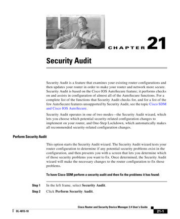
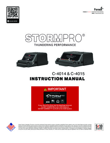
TMFE NIE X // 2018 // INSTRUCTION MANUALWE B // w w w.feniex .comIs this the latest version?SCAN HEREC-4014 & C-4015INSTRUCTION MANUALIMPORTANTIf your Storm Pro Siren has the label/logo pictured,it is NOT COMPATIBLE with 4200 DataLink.DO NOT CONNECT IT via RJ45 to the 4200 System.Feniex Product Copyrights This price List and the mentioned Feniex products include or describe copyrighted Feniex material. Laws in the United States and other countriespreserve for Feniex Industries and its licensors certain exclusive rights for copyrighted material, including the exclusive right to copy, reproduce in any form, distribute and makederivative works of the copyrighted material. Accordingly, any copyrighted material of Feniex and its licensors contained herein or in the Feniex products described in this PriceList may not be copied, reproduced, distributed, merged or modified, transmitted, transcribed, stored in retrieval system or translated into any language or computer language,in any form or by any means, without prior written permission of Feniex Industries, Inc. Feniex and the stylized Feniex logo are registered in the U.S. Patent & Trademark Office.
TABLE OF CONTENTSTMSafety Regulations & WarrantyService after ExpirationCopyrightFeniex Product Copyright3333Box Contents, Specifications, & DimensionsBox ContentsDimensionsSpecifications4444Wiring InformationWiring Information55Installation InstructionsPowerSpeaker ConnectionSiren Tone ActivationPower-Up FunctionalitySiren Tone SelectionSiren TonesAudio Tones66666666Configuration InstructionsPark-KillSiren Tone OverridesRadio Rebroadcast InputsRadio Rebroadcast ActivationDual Siren DelayHorn-Ring7777777Mounting InstructionsStorm 100w Amplifer MountingStorm 200w Amplifier Mounting8882FE NIE X // 2018 // INSTRUCTION MANUAL // v2.0WE B // w w w.feniexindustries.com
SAFETY REGULATIONS & WARRANTYSAFETY REGULATIONSThe following provides all the information necessary tosafely operate the previously listed products of FeniexIndustries, Inc. Please read this manual thoroughly beforeinstalling or operating your new product in order toprevent any damage or injury. Failure to follow the listedinstructions in this manual may result in damage to yourproducts or personal injury. Proper installation of this product requires goodknowledge of automotive systems, electronics &procedures. Please guarantee all vital components of the vehicleare not in danger of being damaged by drilling holesnecessary for installation. Check all sides of themounting surface before drilling any holes into thevehicle. Do not install this product in any way that interfereswith the deployment of the air bag. Doing so maydamage the effectiveness of the air bag & can lead toserious personal and vehicle injury. The installer willassume full responsibility of proper installation of thenew unit. Please clean the mounting surface before installationof the unit when using tape, brackets, magnet, Velcro orsuction cups. The product’s ground wire must be connected directlyto the negative (-) battery post for effective use of theunit. Please follow all wiring guidelines provided toguarantee long lifespan & productivity. Failing to followthese instructions may result in damage to the product.WARRANTYFeniex Industries, Inc. warrants to the original purchaserthat the product shall be free from defects in material &workmanship for 5 years from the date of purchase forall LED products. Feniex Industries warranties speakers,sirens, flashers, & controllers for 2 years.If warranty service is needed, please contact customersupport:Phone: 1.800.615.8350Web Site: www.Feniex.com/supportEmail: techsupport@feniex.comIf the product needs to be returned for repair orreplacement, contact our customer service team (usingany method listed above) to receive a Return MerchandiseAuthorization (RMA) number. Operational times are from 9a.m. to 6 p.m. central time, Monday through Friday.Please do not send in product without contacting support firstfor a Return Merchandise Authorization (RMA) number.3FE NIE X // 2018 // INSTRUCTION MANUAL // v2.0WE B // w w w.feniexindustries.comTMCONDITIONSFeniex Industries, Inc. will not be held responsible for anycosts associated with equipment removal and/orre-installation resulting from a warranty claim. It is the soleresponsibility of the party initiating a warranty claim to payshipping charges associated with returning a product toFeniex Industries for repair or replacement.SERVICE AFTER EXPIRATIONFeniex Industries will still provide service for all productsafter expiration of the warranty. For any issues, call thecustomer support line. In some instances it may benecessary for the product to be shipped, freight prepaidand insured for loss or damage to Feniex headquarters.Utilizing non-factory screws and mounting brackets may resultin the loss of warranty coverage.COPYRIGHTThis instruction manual and the Feniex productsdescribed in this instruction manual may include ordescribe copyrighted Feniex material. Laws in the UnitedStates and other countries preserve for Feniex Industriesand its licensors certain exclusive rights for copyrightedmaterial, including the exclusive right to copy, reproducein any form, distribute and make derivative works ofthe copyrighted material. Accordingly, any copyrightedmaterial of Feniex and its licensors contained herein or inthe Feniex products described in this instruction manualmay not be copied, reproduced, distributed, mergedor modified in any manner without the express writtenpermission of Feniex Industries, Inc.FENIEX PRODUCT COPYRIGHTSThe products described in this document are the propertyof Feniex Industries, Inc. It is furnished by express licenseagreement only and may be used only in accordance with theterms of such an agreement. Products and documentationare copyrighted materials. Making unauthorized copies isprohibited by law. No part of the product or documentationmay be reproduced, transmitted, transcribed, stored inretrieval system or translated into any language or computerlanguage, in any form or by any means, without priorpermission from Feniex Industries, Inc.
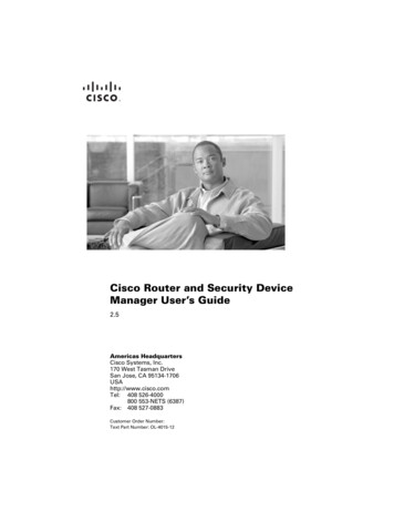
BOX CONTENTS, DIMENSIONS, SPECIFICATIONSBOX CONTENTSTMDIMENSIONSCOMPONENTS: STORM PRO 100 WATTQUANTITYStorm Pro 100w Amplifier1*Microphone S: STORM PRO 200 WATTQUANTITYStorm Pro 200w Amplifier1*Microphone STEM SPECIFICATIONSInput Voltage12 VDCStandby Current30mAMax AmperageIMPORTANTImpedanceSiren OutputSiren VoltageMic DimensionsIf your Storm Pro Siren has the label/logo pictured,it is NOT COMPATIBLE with 4200 DataLink.DO NOT CONNECT IT via RJ45 to the 4200 System.4FE NIE X // 2018 // INSTRUCTION MANUAL // v2.0WE B // w w w.feniexindustries.com10 Amps (onboard fuse: 20a)11 Ohms100 Watts or 200 Watts35v RMS100w Dimensions4.09" W x 6.96" D x 2.50" HHousingAluminum200w DimensionsExternal FuseWarranty6.65" W x 6.96" D x 2.50" H125% of Circuit Load2 Years
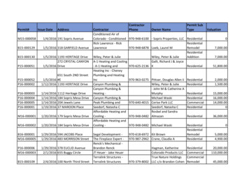
WIRINGTMAKEYABCDEFBFUNCTIONPositiveGroundHITone 112v ( )Tone 312v ( )Tone 212v ( )Tone 412v ( )RebroadcastKRadio InputMGF12v (-)ILE12v ( )Horn RingJDPOLARITYGHC12v ( )Park KillRadio Input100w Speaker100w Speaker12v ( )12v ( )N/AN/AN/AN/AJKLMCONNECTIONPositive TerminalGround TerminalLatching SwitchA BKEYABLatching SwitchIHJRadio Speaker OutputKSpeaker TerminalMLNOPQFE NIE X // 2018 // INSTRUCTION MANUAL // v2.0WE B // w w w.feniexindustries.comPositiveGroundTone 2/Speaker 1Tone 4/Speaker 1Tone 5/Speaker 1Tone 6/Speaker 1Tone 1/Speaker 2Tone 2/Speaker 2Tone 3/Speaker 2Tone 4/Speaker 2Tone 5/Speaker 2Tone 6/Speaker 2Dual DelayHorn RingPark KillRRebroadcastTRadio InputS5FUNCTIONIJKLMNPOLARITY12v ( )12v (-)12v ( )GIf your Storm Pro Siren has the label/logo pictured,it is NOT COMPATIBLE with 4200 DataLink.DO NOT CONNECT IT via RJ45 to the 4200 System.HTone 3/Speaker 1Vehicle Horn SignalIMPORTANTGEFSpeaker TerminalF12v ( )Latching SwitchRadio Speaker OutputETone 1/Speaker 1DVehicle Park SignalDCLatching SwitchLatching SwitchCRadio InputU100w Speaker 2W100w Speaker 1VX100w Speaker 2100w Speaker 112v ( )12v ( )12v ( )12v ( )12v ( )12v ( )12v ( )12v ( )12v ( )12v ( )12v ( )12v ( )12v ( )12v ( )N/AN/AN/AN/AN/AN/AOPQRSTUVWXCONNECTIONPositive TerminalGround TerminalLatching SwitchLatching SwitchLatching SwitchLatching SwitchLatching SwitchLatching SwitchLatching SwitchLatching SwitchLatching SwitchLatching SwitchLatching SwitchLatching SwitchLatching SwitchVehicle Horn SignalVehicle Park SignalLatching SwitchRadio Speaker OutputRadio Speaker OutputSpeaker 2 TerminalSpeaker 2 TerminalSpeaker 1 TerminalSpeaker 1 Terminal
INSTALLATION INSTRUCTIONSPOWERTo power the unit, extend the red wire to a 12v ( ) post.Extend the black wire to the ground post.SPEAKER CONNECTIONConnect the speaker(s) to the corresponding output(dependant on the siren model as shown below): Storm Pro 100w Outputs L & M Storm Pro 200w Outputs W & X (not polarity dependant) Outputs U & V (not polarity dependant)SIREN TONE ACTIVATIONTo activate siren tones, apply power to the correspondinginput (dependant on siren model as shown below: Storm Pro 100w Inputs C, D, E, & F Storm Pro 200w Inputs C, D, E, F, G, & H for speaker #1 Inputs I, J, K, L, M, & N for speaker #21) Wail13) Ecto Siren3) Fast Yelp15) Move Out of the Way2) Yelp4) Phaser5) Mechanical7) Hi/Lo8) P-Call [Slow]9) P-Call [Fast]10) Horn & Phaser11) Horn & Yelp12) Phaser & YelpTone Select ButtonIMPORTANTIf your Storm Pro Siren has the label/logo pictured,it is NOT COMPATIBLE with 4200 DataLink.DO NOT CONNECT IT via RJ45 to the 4200 System.FE NIE X // 2018 // INSTRUCTION MANUAL // v2.014) Bad Boys16) Pull Over17) Step Out of the Vehicle18) Step Out w/Hands Up19) Remain in your Vehicle20) Remain. Windows Down21) Test Tone22) Italian Police*23) Italian Ambulance**Storm Pro 100w OnlyAUDIO TONESEctosirenSiren ToneMove Out of the WayVoice CommandBad BoysSIREN TONE SELECTIONTo cycle through tones activate desired port andmomentarily press the tone selector switch to cycle tonext tone.WE B // w w w.feniexindustries.comSIREN TONES6) Manual WailSpeaker outputs are not polarity dependant.6TMPull OverStep Out of the VehicleStep Out Hands UpRemain in Your VehicleSongVoice CommandVoice CommandVoice CommandVoice CommandRemain in Vehicle. Windows Down Voice CommandFor a single speaker, an activated tone with a higher inputnumber overrides an activated tone with a lower input number.For example, if Tone 4 and Tone 3 are both activated forSpeaker 1, the siren will play Tone 4 for Speaker 1.
OPERATING INSTRUCTIONSTMPARK-KILLPark-Kill is used to deactivate any activated standard sirentone. Park-Kill does not deactivate audio recordings. ThePark-Kill wire can be connected to your vehicle's overheadlight, door trigger, or park-signal so that the siren isdisabled when the door is opened or the vehicle is shiftedto park.DUAL SIREN DELAYDual Delay can be used when both speakers play thesame standard siren tone. When Dual Delay is activated,the tones start playing out of sync to create the delayeffect. Dual Delay applies only for standard siren toneswith Dual Delay capability. Dual Delay does not affectaudio tones.SIREN TONE OVERRIDEWhen either Radio Rebroadcast or the Microphone isactivated, any activated tone, standard siren tone or audiorecording, gets deactivated.HORN-RINGHorn Ring can be used as a standard vehicle horn or usedto quickly switch between two standard siren tones. Touse Horn Ring as a vehicle horn, simply do not activateany of the tone inputs.To use Horn Ring for tone switching, activate an inputconfigured to a tone with Horn Ring capability.Momentarily activate the Horn Ring to switch between theconfigured tone and its alternate tone. Horn Ring does notaffect audio tones.RADIO REBROADCAST INPUTSTo allow for the ability to rebroadcast your emergencyband radio, simply splice in a wire to each of the twocoming from the radio's speaker output. Connect thosenew wires to the input terminals on the Storm Pro. Polarityis not dependant.RADIO REBROADCAST ACTIVATIONTo activate your radio's rebroadcast through the sirenamplifier/speaker, provide power to the the followingterminal: Storm Pro 100w Input I Storm Pro 200w Input RIMPORTANTIf your Storm Pro Siren has the label/logo pictured,it is NOT COMPATIBLE with 4200 DataLink.DO NOT CONNECT IT via RJ45 to the 4200 System.7FE NIE X // 2018 // INSTRUCTION MANUAL // v2.0WE B // w w w.feniexindustries.com
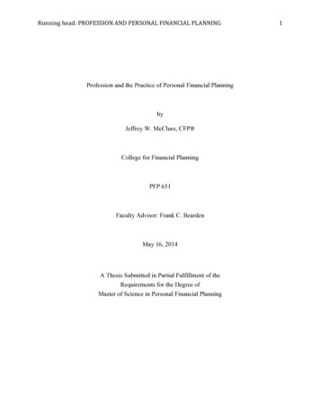
MOUNTING INSTRUCTIONSTMSTORM PRO 100 WATT & 200 WATT AMPLIFIER MOUNTING1) Place the unit against the intended mounting surface.2) Mark the areas where the mounting holes will be drilled. If the mounting surface is part of the vehicle, make sure novital components could be damaged by the drilling process.3) Pre-drill four 1/16" mounting holes on the mounting surface, making sure no vital components of the surface aredamaged.4) Make sure to deburr the holes thoroughly.1.9685”6.9675”6.9675”1.9685”5) Using customer provided screws, secure the Storm Pro to the mounting surfaceIMPORTANTIf your Storm Pro Siren has the label/logo pictured,it is NOT COMPATIBLE with 4200 DataLink.DO NOT CONNECT IT via RJ45 to the 4200 System.8FE NIE X // 2018 // INSTRUCTION MANUAL // v2.0WE B // w w w.feniexindustries.com
FENIEX // 201 // INSTRUCTION MANUAL // v2.0 6 WEB // www.feniexindustries.com TM. OPERATING INSTRUCTIONS IMPORTANT If your Storm Pro Siren has the label/logo pictured, it is NOT COMPATIBLE with 4200 DataLink. DO NOT CONNECT IT via RJ45 to the 4200 System. DUAL SIREN DELAY