Transcription
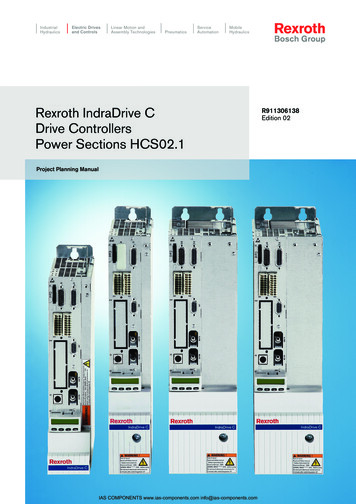
IndustrialHydraulicsElectric Drivesand ControlsLinear Motion andAssembly ulicsRexroth IndraControl VCP 20Rexroth IndraDrive CDrive ControllersPower Sections HCS02.1Project Planning ManualIAS COMPONENTS www.ias-components.com info@ias-components.comR911306138Edition 02
About this DocumentationTitleIndraDrive CRexroth IndraDrive CDrive ControllersPower Sections HCS02.1Type of DocumentationDocument TypecodeInternal File ReferenceRecord of RevisionsCopyrightProject Planning ManualDOK-INDRV*-HCS02.1****-PR02-ENDocument number INDRV*-HCS02.1****-PR01-EN04.2004First EditionDOK-INDRV*-HCS02.1****-PR02-EN02.2005 Bosch Rexroth AG technical dataadded (soundpressure level,mains supply) further load andcurrent profilesadded structure ofmanual hasbeen adapted tostructure ofProject PlanningManual"RexrothIndraDrive DriveSystem"2004 2005Copying this document, giving it to others and the use or communicationof the contents thereof without express authority, are forbidden. Offendersare liable for the payment of damages. All rights are reserved in the eventof the grant of a patent or the registration of a utility model or design(DIN 34-1).ValidityPublished byThe specified data only serve to describe the product. No statementsconcerning a certain condition or suitability for a certain application can bederived from our information. The given information does not release theuser from the obligation of own judgement and verification. It must beremembered that our products are subject to a natural process of wearand aging.Bosch Rexroth AGBgm.-Dr.-Nebel-Str. 2 D-97816 Lohr a. MainTelefon 49 (0)93 52 / 40-0 Tx 68 94 21 Fax 49 (0)93 52 / 40-48 85http://www.boschrexroth.de/Abt. EDY/EDY1 (RR/US)NoteThis document has been printed on chlorine-free bleached paper.DOK-INDRV*-HCS02.1****-PR02-EN-PIAS COMPONENTS www.ias-components.com info@ias-components.com
Contents IRexroth IndraDrive CContents1Introduction1.11-1Documentation. 1-1Purpose of Documentation . 1-1Documentations - Overview . 1-21.2Basic Structure of a Drive Controller . 1-3Power Section. 1-3Control Section . 1-41.3Drive Controllers - Block Diagram . 1-4HCS02.1E-W0012-NNNN . 1-4HCS02.1E-W0012-NNNV. 1-5HCS02.1E-W0028-NNNN . 1-5HCS02.1E-W0028-NNNV. 1-6HCS02.1E-W0054/70-NNNN . 1-6HCS02.1E-W0054/70-NNNV. 1-71.42General Information . 1-8Important Directions for Use2.12-1Appropriate Use. 2-1Introduction . 2-1Areas of Use and Application . 2-22.23Inappropriate Use . 2-2Safety Instructions for Electric Drives and Controls3-13.1Introduction . 3-13.2Explanations . 3-13.3Hazards by Improper Use. 3-23.4General Information . 3-33.5Protection Against Contact with Electrical Parts. 3-53.6Protection Against Electric Shock by Protective Low Voltage (PELV) . 3-63.7Protection Against Dangerous Movements . 3-73.8Protection Against Magnetic and Electromagnetic Fields During Operation andMounting . 3-93.9Protection Against Contact with Hot Parts. 3-103.10 Protection During Handling and Mounting. 3-103.11 Battery Safety . 3-113.12 Protection Against Pressurized Systems. 3-114Identification4.14-1Device Types . 4-1DOK-INDRV*-HCS02.1****-PR02-EN-PIAS COMPONENTS www.ias-components.com info@ias-components.com
II ContentsRexroth IndraDrive CType Code . 4-14.2Type Plates . 4-2Type Plate Arrangement. 4-2Type Plate Power Section (Example). 4-2Type Plate Control Section. 4-24.35Scope of Delivery. 4-3Mechanical Data5.15-1Dimensions . 5-1HCS02.1E-W0012 . 5-1HCS02.1E-W0028 . 5-2HCS02.1E-W0054 and HCS02.1E-W0070 . 5-35.2Weight. 5-45.3Temperatures Above the Top of the Device. 5-5Outlet Temperatures in Normal Operation . 5-66Electrical Data6-16.1Power Section– Mains Supply. 6-16.2Power Section – DC Bus . 6-26.3Power Section – DC Bus Power . 6-3Allowed DC Bus Continuous Power with Three-Phase Mains Connection. 6-5Allowed DC Bus Continuous Power with Single-Phase Mains Connection . 6-6Mains Connection Power and DC Bus Continuous Power . 6-76.4Power Section – Braking Resistor . 6-96.5Power Section – Inverter . 6-106.6Power Section - Examples of Allowed Load Profiles. 6-116.7Power Section – Cooling, Power Dissipation, Insulation Resistance, Sound Pressure. 6-136.8Control Voltage . 6-18Devices without Internal Control Voltage Supply (HCS02.1E-W00xx-NNNN). 6-18Devices with Internal Control Voltage Supply Generation from DC bus(HCS02.1E-W00xx-NNNV). 6-196.9Connections . 6-21Complete Connection Diagram . 6-21Connections at HCS02.1E-W0012. 6-22Connections at HCS02.1E-W0028, -W0054, -W0070 . 6-24X1, Module Bus . 6-27X3, Mains Connection . 6-28X5, Motor Connection. 6-30X6, Motor Temperature Monitoring and Motor Holding Brake . 6-32X9, Connection of Braking Resistor. 6-35X13, Control Voltage ( 24 V, 0 V) . 6-36DC Bus (L , L-). 6-39Connection Point of Equipment Grounding Conductor and Equipment GroundingConnections. 6-40Ground Connection of Housing . 6-40XS1, Shield Connection (Control Wires) . 6-41XS2, Shield Connection (Motor Cable) . 6-42DOK-INDRV*-HCS02.1****-PR02-EN-PIAS COMPONENTS www.ias-components.com info@ias-components.com
Contents IIIRexroth IndraDrive C78Touch Guard7-17.1Cutouts. 7-17.2Mounting . 7-2Disposal and Environmental Protection8.18-1Disposal . 8-1Products. 8-1Packaging Materials . 8-18.2Environmental Protection. 8-1No Release of Hazardous Substances . 8-1Materials Contained in the Products . 8-1Recycling . 8-29Service & Support9-19.1Helpdesk . 9-19.2Service-Hotline . 9-19.3Internet. 9-19.4Vor der Kontaktaufnahme. - Before contacting us. . 9-19.5Kundenbetreuungsstellen - Sales & Service Facilities . 9-210 Index10-1DOK-INDRV*-HCS02.1****-PR02-EN-PIAS COMPONENTS www.ias-components.com info@ias-components.com
IV ContentsRexroth IndraDrive CDOK-INDRV*-HCS02.1****-PR02-EN-PIAS COMPONENTS www.ias-components.com info@ias-components.com
Introduction 1-1Rexroth IndraDrive C1Introduction1.1DocumentationPurpose of DocumentationThis documentation basically contains the technical data of the RexrothIndraDrive C HCS02.1 drive controllers.Personal injury and property damage caused byincorrect project planning for applications,machines and installations!WARNING Take the content of the Project Planning Manual"Rexroth IndraDrive Drive System" (DOK-INDRV*SYSTEM*****-PRxx-EN-P; part no. R911309636)into account.For complete project planning of a Rexroth IndraDrive drive system youneed, in any case, the Project Planning Manual "Rexroth IndraDrive DriveSystem" (DOK-INDRV*-SYSTEM*****-PRxx-EN-P; part no. R911309636).This Project Planning Manual, among other things, contains: specifications for the components of the drive system configuration of the drive system components arrangement of the components in the control cabinet electromagnetic compatibility (EMC) types of mains connection requirements to the mains connection control circuits for the mains connection connections of the components in the drive system fusing and selecting the mains contactor accessories in the drive system calculations (determining appropriate drive controller; mainsconnection; leakage capacitance; operating data of mains filters;selecting the 24V supply; braking behavior when using a DC busresistor unit) Replacing devicesDOK-INDRV*-HCS02.1****-PR02-EN-PIAS COMPONENTS www.ias-components.com info@ias-components.com
1-2 IntroductionRexroth IndraDrive CDocumentations - OverviewFor project planning a drive system following documentations areavailable:1)TitleType of DocumentationDocument TypecodeRexroth IndraDriveDrive SystemProject Planning ManualDOK-INDRV*-SYSTEM*****-PRxx-EN-PRexroth IndraDriveDrive ControllersControl SectionsProject Planning ManualDOK-INDRV*-CSH********-PRxx-EN-PRexroth IndraDrive MDrive ControllersPower SectionsProject Planning ManualDOK-INDRV*-HMS HMD****-PRxx-EN-PRexroth IndraDrive CDrive ControllersPower Sections HCS02.1Project Planning ManualDOK-INDRV*-HCS02.1****-PRxx-EN-PRexroth IndraDrive CDrive ControllersPower Sections HCS03.1Project Planning ManualDOK-INDRV*-HCS03.1****-PRxx-EN-PRexroth IndraDriveSupply UnitsProject Planning tic Compatibility (EMC) inDrive and Control SystemsProject Planning ManualDOK-GENERAL-EMV********-PRxx-EN-PRexroth IndraDriveIntegrated Safety TechnologyFunctional and Application DOK-INDRV*-SI*-**VRS**-FKxx-EN-PDescriptionRexroth Connection CablesSelection DataDOK-CONNEC-CABLE*STAND-AUxx-EN-PSafety Instructions for Electrical DrivesSafety h IndraDriveAdditional ComponentsProject Planning ManualDOK-INDRV*-ADDCOMP****-PRxx-EN-PRexroth IndraDriveFirmware for Drive ControllersFunctional DescriptionDOK-INDRV*-MP*-02VRS**-FKxx-EN-PRexroth IndraDriveFirmware for Drive ControllersParameter DescriptionDOK-INDRV*-GEN-**VRS**-PAxx-EN-PRexroth IndraDriveFirmware for Drive ControllersTroubleshooting GuideDOK-INDRV*-GEN-**VRS**-WAxx-EN-PRexroth IndraDyn SSynchronous Motors MSKProject Planning ManualDOK-MOTOR*-MSK********-PRxx-EN-PRexroth IndraDyn AAsynchronous Motors MAD/MAFProject Planning ManualDOK-MOTOR*-MAD/MAF****-PRxx-EN-PRexroth IndraDyn TSynchronous Torque Motors MBTProject Planning ManualDOK-MOTOR*-MBT********-PRxx-EN-PRexroth IndraDyn HSynchronous Kit –Spindle Motors MBS-HProject Planning ManualDOK-MOTOR*-MBS-H******-PRxx-EN-PRexroth IndraDyn LSynchronous Linear Motors MLFProject Planning ManualDOK-MOTOR*-MLF********-PRxx-EN-PThird Party MotorsProject Planning Manualand CommissioningDOK-DRIVE*-3RDPART*MOT-AWxx-EN-P1)in the document type codes "xx" designates replacement characters forthe update edition of the documentation (Example: "PR01" is the firstedition of a project planning manual)Fig. 1-1: Documentations - OverviewDOK-INDRV*-HCS02.1****-PR02-EN-PIAS COMPONENTS www.ias-components.com info@ias-components.com
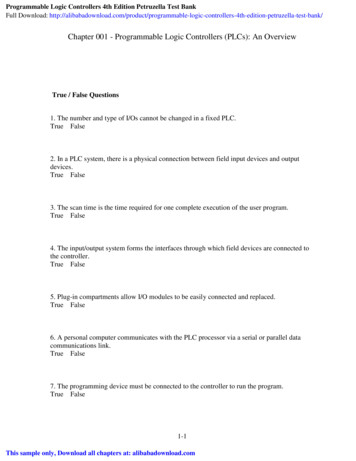
Introduction 1-3Rexroth IndraDrive C1.2Basic Structure of a Drive Controller21hcs lt rt.fh71:Power section2:Control sectionFig. 1-2: Basic structureThe drive controller consists of two essential parts: Power section Control sectionPower SectionThe following are connected to the power section: mains motor (with optional motor holding brake and motor temperaturemonitoring) 24 V power supply DC bus (not for HCS02.1-W0012) module bus (for cross communication in the case of DC busconnection with other devices; not for HCS02.1-W0012) braking resistor (optional; not for HCS02.1-W0012 and –W0028)DOK-INDRV*-HCS02.1****-PR02-EN-PIAS COMPONENTS www.ias-components.com info@ias-components.com
1-4 IntroductionRexroth IndraDrive CControl SectionThe control section is a separate section which is inserted into the powersection. The drive controller is supplied ex works complete with controlsectionThe control section must only be replaced by a trained person.The contacts X31/1 and X31/2 are connected to the control section as Bbcontacts.Note:1.3The control sections are describeddocumentation (see page 1-2).inaseparateDrive Controllers - Block 3line input withbridge circuitrectifierbraking resistorcircuitchargingcurrent limitDC buscapacitanceA3converterbridge circuitwith output tothe motorhcs block 12n.FH7Fig. 1-3:HCS02.1E-W0012-NNNN - Block diagramDOK-INDRV*-HCS02.1****-PR02-EN-PIAS COMPONENTS www.ias-components.com info@ias-components.com
Introduction 1-5Rexroth IndraDrive CHCS02.1E-W0012-NNNVRSoftstartRBL1A1A2L2CZWL3line input withbridge pplybraking resistorcircuitDC buscapacitancechargingcurrent limitA3converterbridge circuitwith output tothe motorhcs block 12v.FH7Fig. 1-4:HCS02.1E-W0012-NNNV - Block diagramHCS02.1E-W0028-NNNNL RSoftstartRBL1A1A2L2CZWL3A3Lline input withbridge circuitrectifierbraking resistorcircuitchargingcurrent limitDC buscapacitanceconverterbridge circuitwith output tothe motorDC busconnectionhcs block 28n.FH7Fig. 1-5:HCS02.1E-W0028-NNNN - Block diagramDOK-INDRV*-HCS02.1****-PR02-EN-PIAS COMPONENTS www.ias-components.com info@ias-components.com
1-6 IntroductionRexroth IndraDrive CHCS02.1E-W0028-NNNVL RSoftstartRBL1A1A2L2CZWL3A3Lline input withbridge pplybraking resistorcircuitDC buscapacitanceconverterbridge circuitwith output tothe motorchargingcurrent limitDC busconnectionhcs block 28v.FH7Fig. 1-6:HCS02.1E-W0028-NNNV - Block diagramHCS02.1E-W0054/70-NNNNL 2CZWL3A3Lline input withbridge circuitrectifierbraking resistorcircuitchargingcurrent limitDC buscapacitanceconverterbridge circuitwith output tothe motorDC busconnectionhcs block 54 70n.FH7Fig. 1-7:HCS02.1E-W0054/70-NNNN - Block diagramDOK-INDRV*-HCS02.1****-PR02-EN-PIAS COMPONENTS www.ias-components.com info@ias-components.com
Introduction 1-7Rexroth IndraDrive CHCS02.1E-W0054/70-NNNVL 2CZWL3A3Lline input withbridge pplybraking resistorcircuitchargingcurrent limitDC busconverterDC buscapacitance bridge circuit connectionwith output tothe motorhcs block 54 70v.FH7Fig. 1-8:HCS02.1E-W0054/70-NNNV - Block diagramDOK-INDRV*-HCS02.1****-PR02-EN-PIAS COMPONENTS www.ias-components.com info@ias-components.com
1-8 Introduction1.4Rexroth IndraDrive CGeneral InformationDamage can be caused to the drive controller or circuit boards ifelectrostatic charging present in people and/or tools is discharged acrossthem. Therefore, please note the following information:Electrostatic charges can cause damage toelectronic components and interfere with theiroperational safety!CAUTION Objectscoming into contact with components andcircuit boards must be discharged by means ofgrounding. Otherwise errors may occur whentriggering motors and moving elements.Such objects include: the copper bit when soldering the human body (ground connection caused by touching a conductive,grounded item) parts and tools (placing on a conductive support)Endangered components may only be stored or dispatched in conductivepackaging.Note:Rexroth connection diagrams are only to be used forproducing installation connection diagrams. The machinemanufacturer’s installation connection diagrams must be usedfor wiring the installation! Lay signal lines separately from the load resistance lines because ofthe occurrence of interference. Feed analog signals (e.g., command values, actual values) viasheathed lines. Do not connect mains, DC bus or power leads to low voltages or allowthem to come into contact. When carrying out a high voltage test or insulation withstand test onthe machine’s electrical equipment, disconnect all connections to theunits. This protects the electronic components (permitted inaccordance with EN 60204-1). During their routine check test, Rexrothdrive components are tested for high voltage and insulation inaccordance with EN 50178.Plugging and unclamping live connections candamage the controller. Do not plug in or unclamp live PIAS COMPONENTS www.ias-components.com info@ias-components.com
Important Directions for Use 2-1Rexroth IndraDrive C2Important Directions for Use2.1Appropriate UseIntroductionRexroth products represent state-of-the-art developments andmanufacturing. They are tested prior to delivery to ensure operating safetyand reliability.The products may only be used in the manner that is defined asappropriate. If they are used in an inappropriate manner, then situationscan develop that may lead to property damage or injury to personnel.Note:Rexroth, as manufacturer, is not liable for any damagesresulting from inappropriate use. In such cases, the guaranteeand the right to payment of damages resulting frominappropriate use are forfeited. The user alone carries allresponsibility of the risks.Before using Rexroth products, make sure that all the pre-requisites foran appropriate use of the products are satisfied: Personnel that in any way, shape or form uses our products must firstread and understand the relevant safety instructions and be familiarwith appropriate use. If the product takes the form of hardware, then they must remain intheir original state, in other words, no structural changes are permitted.It is not permitted to decompile software products or alter sourcecodes. Do not mount damaged or faulty products or use them in operation. Make sure that the products have been installed in the mannerdescribed in the relevant documentation.DOK-INDRV*-HCS02.1****-PR02-EN-PIAS COMPONENTS www.ias-components.com info@ias-components.com
2-2 Important Directions for UseRexroth IndraDrive CAreas of Use and ApplicationDrive controllers made by Rexroth are designed to control electricalmotors and monitor their operation.Control and monitoring of the motors may require additional sensors andactors.Note:The drive controllers may only be used with the accessoriesand parts specified in this document. If a component has notbeen specifically named, then it may not be either mounted orconnected. The same applies to cables and lines.Operation is only permitted in the specified configurations andcombinations of components using the software and firmwareas specified in the relevant function descriptions.Every drive controller has to be programmed before starting it up, makingit possible for the motor to execute the specific functions of an application.The drive controllers are designed for use in single or multiple-axis driveand control applications.To ensure an application-specific use, the drive controllers are availablewith differing drive power and different interfaces.Typical applications of drive controllers are: handling and mounting systems, packaging and foodstuff machines, printing and paper processing machines and machine tools.The drive controllers may only be operated under the assembly,installation and ambient conditions as described here (temperature,system of protection, humidity, EMC requirements, etc.) and in theposition specified.2.2Inappropriate UseUsing the drive controllers outside of the above-referenced areas ofapplication or under operating conditions other than described in thedocument and the technical data specified is defined as “inappropriateuse".Drive controllers may not be used if they are subject to operating conditions that do not meet the abovespecified ambient conditions. This includes, for example, operationunder water, in the case of extreme temperature fluctuations orextremely high maximum temperatures or if Rexroth has not specifically released them for that intended purpose.Please note the specifications outlined in the general PIAS COMPONENTS www.ias-components.com info@ias-components.com
Safety Instructions for Electric Drives and Controls 3-1Rexroth IndraDrive C3Safety Instructions for Electric Drives and Controls3.1IntroductionRead these instructions before the initial startup of the equipment in orderto eliminate the risk of bodily harm or material damage. Follow thesesafety instructions at all times.Do not attempt to install or start up this equipment without first reading alldocumentation provided with the product. Read and understand thesesafety instructions and all user documentation of the equipment prior toworking with the equipment at any time. If you do not have the userdocumentation for your equipment, contact your local Rexrothrepresentative to send this documentation immediately to the person orpersons responsible for the safe operation of this equipment.If the equipment is resold, rented or transferred or passed on to others,then these safety instructions must be delivered with the equipment.WARNING3.2Improper use of this equipment, failure to followthe safety instructions in this document ortampering with the product, including disablingof safety devices, may result in materialdamage, bodily harm, electric shock or evendeath!ExplanationsThe safety instructions describe the following degrees of hazardseriousness in compliance with ANSI Z535. The degree of hazardseriousness informs about the consequences resulting from noncompliance with the safety instructions.Warning symbol with signalwordDegree of hazard seriousness accordingto ANSIDeath or severe bodily harm will occur.DANGERDeath or severe bodily harm may occur.WARNINGBodily harm or material damage may occur.CAUTIONFig. 3-1:Hazard classification (according to ANSI Z535)DOK-INDRV*-HCS02.1****-PR02-EN-PIAS COMPONENTS www.ias-components.com info@ias-components.com
3-2 Safety Instructions for Electric Drives and Controls3.3Rexroth IndraDrive CHazards by Improper UseHigh voltage and high discharge current!Danger to life or severe bodily harm by electricshock!DANGERDangerous movements! Danger to life, severebodily harm or material damage byunintentional motor movements!DANGERHigh electrical voltage due to wrongconnections! Danger to life or bodily harm byelectric shock!WARNINGHealth hazard for persons with heartpacemakers, metal implants and hearing aids inproximity to electrical equipment!WARNINGSurface of machine housing could be extremelyhot! Danger of injury! Danger of burns!CAUTIONCAUTIONRisk of injury due to improper handling! Bodilyharm caused by crushing, shearing, cutting andmechanical shock or incorrect handling ofpressurized systems!Risk of injury due to incorrect handling ofbatteries!CAUTIONDOK-INDRV*-H
1-4 Introduction Rexroth IndraDrive C DOK-INDRV*-HCS02.1****-PR02-EN-P Control Section The control section is a separate section which is inserted into the power section. The drive controller is supplied ex works complete with control section The control section must only be replaced by a trained person.