Transcription
Service PartsGenerator Set ControllersModels:20--3250 kWControllers:Decision-MakerR 1Decision-MakerR 3, 3 , 340, and 550Paralleling Engine Gauge BoxTP-6009 9/12k
Table of ContentsSection 1 Introduction . . . . . . . . . . . . . . . . . . . . . . . . . . . . . . . . . . . . . . . . . . . . . . . . . . . . . . . . . . . . . . . . . . . . .1.11.2Identifying the Controller Group Parts . . . . . . . . . . . . . . . . . . . . . . . . . . . . . . . . . . . . .Identifying the Controller Assembly Service Part Numbers . . . . . . . . . . . . . . . . . . .Section 2 Controller Group Data . . . . . . . . . . . . . . . . . . . . . . . . . . . . . . . . . . . . . . . . . . . . . . . . . . . . . . . . . . . .Section 3 Controller Group Parts (20-- 300 kW) . . . . . . . . . . . . . . . . . . . . . . . . . . . . . . . . . . . . . . . . . . . . . . .Section 4 Controller Group Parts (350/400 kW) . . . . . . . . . . . . . . . . . . . . . . . . . . . . . . . . . . . . . . . . . . . . . . .Section 5 Controller Group Parts (450-- 2000 kW) . . . . . . . . . . . . . . . . . . . . . . . . . . . . . . . . . . . . . . . . . . . . .Section 6 Controller Group Parts (2500-- 3250 kW) . . . . . . . . . . . . . . . . . . . . . . . . . . . . . . . . . . . . . . . . . . . .Section 7 Transformers . . . . . . . . . . . . . . . . . . . . . . . . . . . . . . . . . . . . . . . . . . . . . . . . . . . . . . . . . . . . . . . . . . . .Section 8 Decision-MakerR 3 Controller Assembly . . . . . . . . . . . . . . . . . . . . . . . . . . . . . . . . . . . . . . . . . .Section 9 Ammeters . . . . . . . . . . . . . . . . . . . . . . . . . . . . . . . . . . . . . . . . . . . . . . . . . . . . . . . . . . . . . . . . . . . . . . .Section 10 Decision-MakerR 340 Controller Assembly . . . . . . . . . . . . . . . . . . . . . . . . . . . . . . . . . . . . . . . .Section 11 Decision-MakerR 550 Controller Assembly . . . . . . . . . . . . . . . . . . . . . . . . . . . . . . . . . . . . . . . .Section 12 Paralleling Engine Gauge Box Assembly . . . . . . . . . . . . . . . . . . . . . . . . . . . . . . . . . . . . . . . . .Section 13 Decision-MakerR 1 Controller Assembly . . . . . . . . . . . . . . . . . . . . . . . . . . . . . . . . . . . . . . . . . .Appendix A Abbreviations . . . . . . . . . . . . . . . . . . . . . . . . . . . . . . . . . . . . . . . . . . . . . . . . . . . . . . . . . . . . . . . . .Appendix B Common Hardware Application Guidelines . . . . . . . . . . . . . . . . . . . . . . . . . . . . . . . . . . . . . .Appendix C General Torque Specifications . . . . . . . . . . . . . . . . . . . . . . . . . . . . . . . . . . . . . . . . . . . . . . . . . .Appendix D Common Hardware Identification . . . . . . . . . . . . . . . . . . . . . . . . . . . . . . . . . . . . . . . . . . . . . . .Appendix E Common Hardware List . . . . . . . . . . . . . . . . . . . . . . . . . . . . . . . . . . . . . . . . . . . . . . . . . . . . . . . .55573234353638505257586062A-1A-3A-4A-5A-6
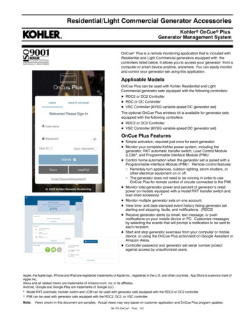
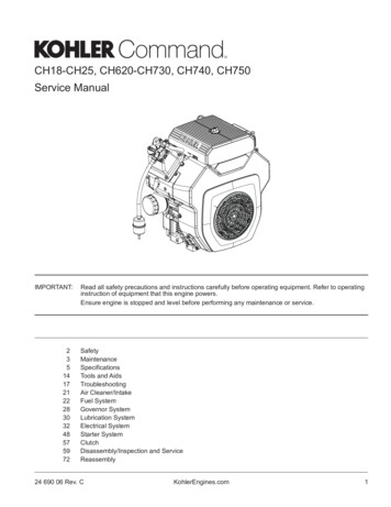
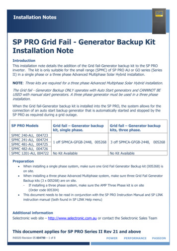
Section 1 IntroductionThis manual lists service replacement parts forgenerator set controller groups and controller kits.3. Locate in the first column of Chart 1 thegenerator set spec number or the installedcontroller kit number found in step 1.1.1 Identifying the ControllerGroup PartsThe controller group contains the controller assembly,controller mounting hardware, sensors, transformers,wiring harnesses, and other related parts. Follow thesteps below to identify controller group service partnumbers.4. Read across Chart 1 and locate in the lastcolumn the catalog section number that listscontroller group parts. See Figure 2.RKOHLER CO. KOHLER WI. USAMODEL 20RZSERIALACCESSORIES:27274827473927642322266111. Locate the generator set nameplate to identifythe generator set specification (spec)number.SAFEGUARD BREAKERRAD. COOLING 105DEG.DEC-- 3 CONTROLLERSTANDBY NAMEPLATE2orLocate the generator set nameplate listingaccessories to identify an optional installedcontroller kit number. On some models thisnameplate is mounted inside the generatorjunction box. See Figure 1 for an example of thenameplate.327004-B1. Factory-installed kit number2. Kit description2. Turn to Chart 1—Controller Group Data inSection 2. The first column lists generator setspec numbers and installed controller kitnumbers. See Figure 2 below for an 24276425Figure 1 Generator Accessory NameplateChart 1: Controller Group DataControllerAssemblyGenerator SetPartkWVolts (AC) NumberController Type15015015020202011. Spec or kit number2. Controller assembly part 16-Light7-Light16-Light23. Controller type4. Section Number3Controller BatteryBox Size Volts sized121212121212CatalogSection22222246009 2Figure 2 Data Chart ExampleTP-6009 9/125
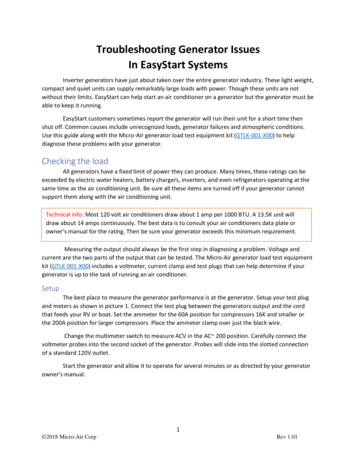
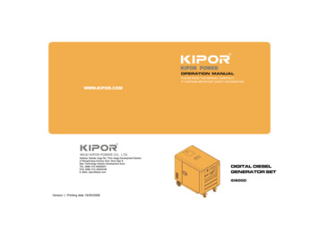
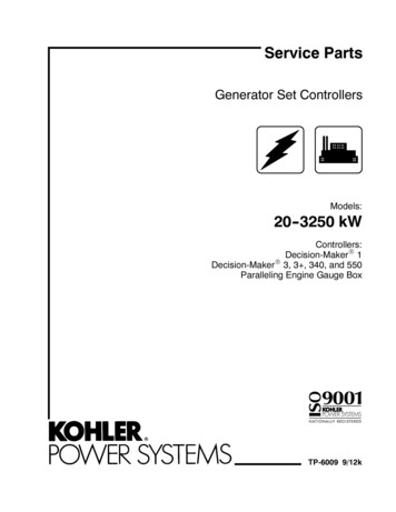
5. Turn to the section indicated in step 4.6. Use the drawing and itemized text to locate thepart and its part number.5. Turn to Chart 3—Controller Ammeter in section 9for ammeter part numbers. See Figure 4.Chart 3: AmmetersPart NumberItem 5,ControllerAmmeterAssembly7. Turn to Chart 2—Controller Transformers insection 7 for transformer part numbers. SeeFigure 3.Chart 2: Controller TransformersPart NumberPotentialCurrentKit/SpecNumber Transformer NA1. Spec or kit number2. Transformer part 917A-328918A-3289192828072828002828002828011. Controller assembly part number2. Ammeter part number26009 4Figure 4 Ammeter Chart Example26009 3Figure 3 Transformer Chart Example1.2 Identifying the ControllerAssembly Service PartNumbersThe controller assembly includes control circuitry,connection terminals, and other related parts. Followthe steps below to identify controller assembly servicepart numbers.1. Complete steps 1--3 of section 1.1, Identifying theController Group Parts to identify the controllergroup parts.2. Read across Chart 1 in Section 2 and locate thecontroller assembly part number andcontroller type. See Figure 2.3. Find the page number of the controller type in theTable of Contents and turn to that page to locatethe controller type.4. Use the drawing and itemized text to locate thepart and its part number.6TP-6009 9/12
Section 2 Controller Group DataThis chart lists specification (spec) number and controller kit data. The chart is sorted by Controller Kit/spec number.ControllerKit/SpecNumberGenerator SetkWChart 1: Controller Group DataControllerAssemblyPartNumberVolts (AC)Controller TypeControllerBox 099/127
Section 2 Controller Group Data, continuedControllerKit/SpecNumberGenerator SetkWChart 1: Controller Group Data, continuedControllerAssemblyPartNumberVolts (AC)Controller TypeControllerBox P-60099/12
Section 2 Controller Group Data, continuedControllerKit/SpecNumberGenerator SetkWChart 1: Controller Group Data, continuedControllerAssemblyPartNumberVolts (AC)Controller TypeControllerBox 60099/129
Section 2 Controller Group Data, continuedControllerKit/SpecNumberGenerator SetkWChart 1: Controller Group Data, continuedControllerAssemblyPartNumberVolts (AC)Controller TypeControllerBox tStandard12310TP-60099/12
Section 2 Controller Group Data, 3189915189920189921189922189926189927TP-6009 9/12Generator 80180180180180180180180180180180Chart 1: Controller Group Data, continuedControllerAssemblyPartNumberVolts (AC)Controller rBox 33333333333333333333333333333333311
Section 2 Controller Group Data, 519424619424719424819425519425619425712Generator 75275275275200200200200230230230Chart 1: Controller Group Data, continuedControllerAssemblyPartNumberVolts (AC)Controller ght16-Light16-Light16-Light16-LightControllerBox 333333333333333333333333333333333TP-6009 9/12
Section 2 Controller Group Data, 3273874273875273876273877273878273879TP-6009 9/12Generator 125125Chart 1: Controller Group Data, continuedControllerAssemblyPartNumberVolts (AC)Controller t7-Light16-LightControllerBox 33333333333334444444444333333333333333333313
Section 2 Controller Group Data, 3Generator 5Chart 1: Controller Group Data, continuedControllerAssemblyPartNumberVolts (AC)Controller -Light7-LightEngine ker 1 w/gauges and meterDecision-Maker 1Decision-Maker 1 w/gauges and meterDecision-Maker 1 w/gauges and meterDecision-Maker 1 w/gauges and meterControllerBox 3333333333333333333333333333TP-6009 9/12
Section 2 Controller Group Data, continuedControllerKit/SpecNumberGenerator SetkWChart 1: Controller Group Data, continuedControllerAssemblyPartNumberVolts (AC)Controller 1-110A-328978A-347050364451-66364451-71TP-6009 9/12Decision-Maker 1 w/gauges and meterDecision-Maker 1 w/gauges and meterDecision-Maker 1 w/gauges and meterDecision-Maker 1 w/gauges and meterDecision-Maker 1 w/gauges and meterDecision-Maker 1 w/gauges and meterDecision-Maker 1 w/gauges and meterDecision-Maker 1 w/gauges and meterDecision-Maker 1 w/gauges16-Li
Generator Set Controllers Models: 20--3250 kW Controllers: Decision-Maker 1 Decision-Maker 3, 3 , 340, and 550 Paralleling Engine Gauge Box TP-6009 9/12k