Transcription
Power SystemsSAS RAID controllers for AIX
Power SystemsSAS RAID controllers for AIX
NoteBefore using this information and the product it supports, read the information in “Notices,” onpage 137, “Safety notices” on page vii, the IBM Systems Safety Notices manual, G229-9054, and theIBM Environmental Notices and User Guide, Z125–5823.This edition applies to IBM Power Systems servers that contain the POWER6 processor and to all associatedmodels. Copyright International Business Machines Corporation 2007, 2009.US Government Users Restricted Rights – Use, duplication or disclosure restricted by GSA ADP Schedule Contractwith IBM Corp.
ContentsSafety notices. . . . . . . . . . . . . . . . . . . . . . . . . . . . . . . . viiChapter 1. SAS RAID controllers for AIX overview . . . . . . . . . . . . . . . . . 1Feature comparison of SAS RAID cards .PCI-X SAS RAID card comparison . .PCIe SAS RAID card comparison . .SAS architecture . . . . . . . . .Disk arrays . . . . . . . . . .Supported RAID levels . . . . .RAID 0 . . . . . . . . . .RAID 5 . . . . . . . . . .RAID 6 . . . . . . . . . .RAID 10 . . . . . . . . .Disk array capacities . . . . . .RAID level summary . . . . . .Stripe-unit size . . . . . . . .Valid states for hdisks and pdisks . .States for disk arrays (hdisks) . .States for physical disks (pdisks) .pdisk descriptions . . . . . .Auxiliary write cache . . . . . .Auxiliary write cache adapter . .Installing the auxiliary write cacheViewing link status information .Chapter 2. Controller softwareController software verification . 1. 1. 5. 8. 10. 12. 12. 13. 13. 14. 15. 15. 16. 16. 16. 17. 17. 17. 17. 19. 20. . . . . . . . . . . . . . . . . . . . . . . . . 23. 23Chapter 3. Common controller and disk array management tasks . . . . . . . . . . 25Using the Disk Array Manager . . . . . .Preparing disks for use in SAS disk arrays . .Creating a disk array . . . . . . . . .Migrating an existing disk array to a new RAIDViewing the disk array configuration . . . .Deleting a disk array . . . . . . . . .Adding disks to an existing disk array . . .Using hot spare disks . . . . . . . . .Creating hot spare disks . . . . . . .Deleting hot spare disks . . . . . . .Viewing IBM SAS disk array settings . . . .Viewing IBM SAS pdisk settings . . . . .Viewing pdisk vital product data . . . . .Viewing controller SAS addresses . . . . .Controller SAS address attributes . . . . .AIX command-line interface . . . . . . . . . .level. . . . . . . . . . . . .25262627293031323232323334343435Chapter 4. Multi-initiator and high availability . . . . . . . . . . . . . . . . . . . 37Possible HA configurations . .Controller functions . . . .Controller function attributes .Viewing HA controller attributesHA cabling considerations . .HA performance considerationsHA access optimization . . . Copyright IBM Corp. 2007, 2009.37394142424343iii
HA access characteristics within List SAS Disk Array Configuration . . . . .Configuration and serviceability considerations for HA RAID configurations . .Installing high availability . . . . . . . . . . . . . . . . . . .Installing an HA single-system RAID configuration . . . . . . . . . .Installing an HA two-system RAID configuration. . . . . . . . . . .Functions requiring special attention in an HA two-system RAID configurationInstalling an HA two-system JBOD configuration . . . . . . . . . . .46474848515555Chapter 5. SAS RAID controller maintenance . . . . . . . . . . . . . . . . . . . 59Updating the SAS RAID controller microcode . . . . . . . . . .Changing pdisks to hdisks . . . . . . . . . . . . . . . .Rechargeable battery maintenance . . . . . . . . . . . . . .Displaying rechargeable battery information . . . . . . . . .Error state . . . . . . . . . . . . . . . . . . . . .Forcing a rechargeable battery error . . . . . . . . . . . .Replacing a battery pack . . . . . . . . . . . . . . . . .Replacing a 572B nonconcurrent maintainable battery pack . . . .Replacing a 57B7 concurrent maintainable battery pack . . . . . .Replacing a 574E concurrent maintainable battery pack . . . . . .Replacing a 572F/575C card set concurrent maintainable battery pack .Separating the 572F/575C card set and moving the cache directory card .Replacing the cache directory card. . . . . . . . . . . . . .Replacing pdisks . . . . . . . . . . . . . . . . . . .Viewing SAS fabric path information . . . . . . . . . . . . .Example: Using SAS fabric path information . . . . . . . . . .59606060626263636567686973757677Chapter 6. Problem determination and recovery . . . . . . . . . . . . . . . . . . 83SAS resource locations. . . . . . . .Showing physical resource attributes . . .Disk array problem identification . . . .Service request numbers . . . . . . .Controller maintenance analysis proceduresExamining the hardware error log . . .MAP 3100 . . . . . . . . . . .MAP 3110 . . . . . . . . . . .MAP 3111 . . . . . . . . . . .MAP 3112 . . . . . . . . . . .MAP 3113 . . . . . . . . . . .MAP 3120 . . . . . . . . . . .MAP 3121 . . . . . . . . . . .MAP 3130 . . . . . . . . . . .MAP 3131 . . . . . . . . . .MAP 3132 . . . . . . . . . .MAP 3133 . . . . . . . . . .MAP 3134 . . . . . . . . . .MAP 3135 . . . . . . . . . .MAP 3140 . . . . . . . . . .MAP 3141 . . . . . . . . . .MAP 3142 . . . . . . . . . .MAP 3143 . . . . . . . . . .MAP 3144 . . . . . . . . . .MAP 3145 . . . . . . . . . .MAP 3146 . . . . . . . . . .MAP 3147 . . . . . . . . . .MAP 3148 . . . . . . . . . .MAP 3149 . . . . . . . . . .MAP 3150 . . . . . . . . . .MAP 3152 . . . . . . . . . .MAP 3153 . . . . . . . . . .MAP 3190 . . . . . . . . . .iv. 83. 84. 85. 86. 88. 88. 89. 89. 91. 92. 94. 96. 99. 99. . . . . . . . . . . . . . . . . . . . . . . . 101. . . . . . . . . . . . . . . . . . . . . . . . 105. . . . . . . . . . . . . . . . . . . . . . . . 107. . . . . . . . . . . . . . . . . . . . . . . . 107. . . . . . . . . . . . . . . . . . . . . . . . 111. . . . . . . . . . . . . . . . . . . . . . . . 111. . . . . . . . . . . . . . . . . . . . . . . . 112. . . . . . . . . . . . . . . . . . . . . . . . 113. . . . . . . . . . . . . . . . . . . . . . . . 114. . . . . . . . . . . . . . . . . . . . . . . . 115. . . . . . . . . . . . . . . . . . . . . . . . 119. . . . . . . . . . . . . . . . . . . . . . . . 120. . . . . . . . . . . . . . . . . . . . . . . . 123. . . . . . . . . . . . . . . . . . . . . . . . 124. . . . . . . . . . . . . . . . . . . . . . . . 125. . . . . . . . . . . . . . . . . . . . . . . . 125. . . . . . . . . . . . . . . . . . . . . . . . 128. . . . . . . . . . . . . . . . . . . . . . . . 131. . . . . . . . . . . . . . . . . . . . . . . . 134
Finding a service request number from an existing AIX error log . 135Appendix. Notices . . . . . . . . . . . . . . . . . . . . . . . . . . . . . . 137Trademarks . . . . .Electronic emission noticesClass A Notices. . .Terms and conditions. .138138138142Contentsv
vi
Safety noticesSafety notices may be printed throughout this guide:v DANGER notices call attention to a situation that is potentially lethal or extremely hazardous topeople.v CAUTION notices call attention to a situation that is potentially hazardous to people because of someexisting condition.v Attention notices call attention to the possibility of damage to a program, device, system, or data.World Trade safety informationSeveral countries require the safety information contained in product publications to be presented in theirnational languages. If this requirement applies to your country, a safety information booklet is includedin the publications package shipped with the product. The booklet contains the safety information inyour national language with references to the U.S. English source. Before using a U.S. English publicationto install, operate, or service this product, you must first become familiar with the related safetyinformation in the booklet. You should also refer to the booklet any time you do not clearly understandany safety information in the U.S. English publications.German safety informationDas Produkt ist nicht für den Einsatz an Bildschirmarbeitsplätzen im Sinne § 2 derBildschirmarbeitsverordnung geeignet.Laser safety informationIBM servers can use I/O cards or features that are fiber-optic based and that utilize lasers or LEDs.Laser complianceAll lasers are certified in the U.S. to conform to the requirements of DHHS 21 CFR Subchapter J for class1 laser products. Outside the U.S., they are certified to be in compliance with IEC 60825 as a class 1 laserproduct. Consult the label on each part for laser certification numbers and approval information.CAUTION:This product might contain one or more of the following devices: CD-ROM drive, DVD-ROM drive,DVD-RAM drive, or laser module, which are Class 1 laser products. Note the following information:v Do not remove the covers. Removing the covers of the laser product could result in exposure tohazardous laser radiation. There are no serviceable parts inside the device.v Use of the controls or adjustments or performance of procedures other than those specified hereinmight result in hazardous radiation exposure.(C026)CAUTION:Data processing environments can contain equipment transmitting on system links with laser modulesthat operate at greater than Class 1 power levels. For this reason, never look into the end of an opticalfiber cable or open receptacle. (C027)CAUTION:This product contains a Class 1M laser. Do not view directly with optical instruments. (C028) Copyright IBM Corp. 2007, 2009vii
CAUTION:Some laser products contain an embedded Class 3A or Class 3B laser diode. Note the followinginformation: laser radiation when open. Do not stare into the beam, do not view directly with opticalinstruments, and avoid direct exposure to the beam. (C030)Power and cabling information for NEBS (Network Equipment-Building System)GR-1089-COREThe following comments apply to the IBM servers that have been designated as conforming to NEBS(Network Equipment-Building System) GR-1089-CORE:The equipment is suitable for installation in the following:v Network telecommunications facilitiesv Locations where the NEC (National Electrical Code) appliesThe intrabuilding ports of this equipment are suitable for connection to intrabuilding or unexposedwiring or cabling only. The intrabuilding ports of this equipment must not be metallically connected to theinterfaces that connect to the OSP (outside plant) or its wiring. These interfaces are designed for use asintrabuilding interfaces only (Type 2 or Type 4 ports as described in GR-1089-CORE) and require isolationfrom the exposed OSP cabling. The addition of primary protectors is not sufficient protection to connectthese interfaces metallically to OSP wiring.Note: All Ethernet cables must be shielded and grounded at both ends.The ac-powered system does not require the use of an external surge protection device (SPD).The dc-powered system employs an isolated DC return (DC-I) design. The DC battery return terminalshall not be connected to the chassis or frame ground.viii
Chapter 1. SAS RAID controllers for AIX overviewFind usage and maintenance information regarding controllers for the serial-attached SCSI (SAS)Redundant Array of Independent Disks (RAID) for the AIX operating system. Use this information inconjunction with your specific system unit and operating system documentation. General information isintended for all users of this product. Service information is intended for a service representativespecifically trained on the system unit and subsystem being serviced.The SAS RAID controllers for AIX have the following features:v PCI-X 266 system interface or PCI Express (PCIe) system interface.v Physical link (phy) speed of 3 Gbps SAS supporting transfer rates of 300 MB per second.v Supports SAS devices and non-disk Serial Advanced Technology Attachment (SATA) devices.v Optimized for SAS disk configurations that use dual paths through dual expanders for redundancyand reliability.v Controller managed path redundancy and path switching for multiported SAS devices.v Embedded PowerPC RISC Processor, hardware XOR DMA Engine, and hardware Finite FieldMultiplier (FFM) DMA Engine (for Redundant Array of Independent Disks (RAID) 6).v Some adapters support nonvolatile write cache.v Support for RAID 0, 5, 6, and 10 disk arrays.v Supports attachment of other devices such as non-RAID disks, tape, and optical devices.v RAID disk arrays and non-RAID devices supported as a bootable device.v Advanced RAID features:– Hot spares for RAID 5, 6, and 10 disk arrays– Ability to increase the capacity of an existing RAID 5 or 6 disk array by adding disks– Background parity checking– Background data scrubbing– Disks formatted to 528 bytes per sector, providing cyclical redundancy checking (CRC) and logicallybad block checking– Optimized hardware for RAID 5 and 6 sequential write workloads– Optimized skip read/write disk support for transaction workloadsv Supports a maximum of 64 advanced function disks with a total device support maximum of 255 (thenumber of all physical SAS and SATA devices plus number of logical RAID disk arrays must be lessthan 255 per controller).Feature comparison of SAS RAID cardsCompare the main features of PCI-X and PCI Express (PCIe) SAS RAID cards.These tables provides a breakdown of the main features of the SAS RAID PCI-X and PCIe controllercards.PCI-X SAS RAID card comparisonThis table compares the main features of PCI-X SAS RAID cards. Copyright IBM Corp. 2007, 20091
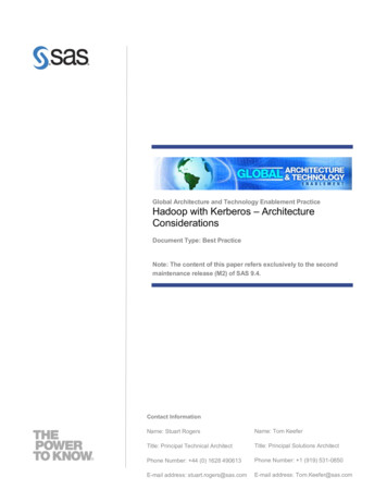
Table 1. PCI-X SAS RAID controller cardsCCIN (customcardidentificationnumber)572A572B572C572F / 575C57B8DescriptionPCI-X 266 ExtPCI-X 266 ExtPCI-X 266 Planar PCI-X 266 ExtDual-x4 3 Gb SAS Dual-x4 3 Gb SAS 3 Gb SAS Adapter Tri-x4 3 Gb SASAdapterRAID AdapterRAID AdapterForm factorLow profile 64-bit Long 64-bit PCI-X Planar integratedPCI-XLong 64-bit PCI-X, Planar RAIDdouble-wide card enablementsetAdapter failingfunction codeLED value2515251725022519 / 251DPhysical links8 (two mini SAS4x connectors)8 (two mini SAS4x connectors)8112 (bottom 3 mini 81SAS 4xconnectors) and 2(top mini SAS 4xconnector for HAonly)RAID levelssupportedRAID 0, 54, 64, 10RAID 0, 5, 6, 10RAID 0RAID 0, 5, 6, 10RAID 0, 5, 6, 10Up to 1.5 Gb(compressed)175 MBWrite cache size175 MBRead cache sizePCI-X 266 Planar3 Gb SAS RAIDAdapter2505Up to 1.6 Gb(compressed)Cache batterypack technologyLiIonLiIonNot applicable2Cache batterypack FFC2D032D065Not applicable2Cache batteryconcurrentmaintenanceNoNoNoYesNot applicable2Cache datapresent LEDNoNoNoNoNoRemovablecache cardNoYesNoNoNoAuxiliary writecache (AWC)supportNoNoNoYesYesHigh availability Yes3(HA) twosystem RAIDYesNoNoNoHA two systemJBODYes3NoNoNoNoHA singlesystem RAIDYes3YesNoNoNoRequires HARAIDconfigurationNoYesNoNoNo2
Table 1. PCI-X SAS RAID controller cards (continued)CCIN (customcardidentificationnumber)1572A572B572C572F / 575C57B8Some systems provide an external mini SAS 4x connector from the integrated backplane controller.2The controller contains battery-backed cache, but the battery power is supplied by the 57B8 controller throughthe backplane connections.3Multi-initiator and high availability is supported on the CCIN 572A adapter except for part numbers of either44V4266 or 44V4404 (feature code 5900).4The write performance of RAID 5 and RAID 6 might be poor on adapters that do not provide write cache.Consider using an adapter that provides write cache when using RAID 5 or RAID 6.5The cache battery pack for both adapters is contained in a single battery FRU, which is physically located on the575C auxiliary cache card.Figure 1. CCIN 572A PCI-X266 External Dual-x4 3 Gb SAS adapterChapter 1. SAS RAID controllers for AIX overview3
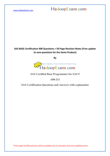
Figure 2. CCIN 572B PCI-X266 Ext Dual-x4 3 Gb SAS RAID adapterFigure 3. CCIN 57B8 planar RAID enablement card4
Figure 4. CCIN 572F PCI-X266 Ext Tri-x4 3 Gb SAS RAID adapter and CCIN 575C PCI-X266 auxiliary cache adapterPCIe SAS RAID card comparisonThis table compares the main features of PCI Express (PCIe) SAS RAID cards.Table 2. PCIe SAS RAID controller cardsCCIN nPCIe x1 AuxiliaryCache AdapterPCIe x8 ExtPCIe x8 ExtPCIe x8 ExtPCIe x8 ExtDual-x4 3 Gb SAS Dual-x4 3 Gb SAS Dual-x4 3 Gb SAS Dual-x4 3 Gb SASAdapter andAdapter andAdapterRAID AdapterCable CardCable CardForm factorPlanar AuxiliaryCacheCombination PCIe Combination PCIe PCIe x8x8 and Cablex8 and CableCardCardPCIe x8Adapter failingfunction codeLED value25042D0B2D0B2518Physical links24 (bottommini-SAS 4xconnectorrequired toconnect by anexternal AI cableto the topmini-SAS 4xCable Cardconnector)8 (two mini SAS8 (two mini SAS4x connectors, one 4x connectors)required toconnect by anexternal AI cableto the topmini-SAS 4xCable Cardconnector)8 (two mini SAS4x connectors)RAID 0, 51, 61, 10RAID 0, 51, 61, 10RAID 0, 5, 6, 10RAID levelssupported57BA57B32516RAID 0, 51, 61, 10574EChapter 1. SAS RAID controllers for AIX overview5
Table 2. PCIe SAS RAID controller cards (continued)CCIN (customcardidentificationnumber)57B7Write cache size175 MB57B957BA57B3574E380 MBRead cache sizeCache batteryLiIonpack technologyLiIonCache batterypack FFC2D052D0ECache batteryconcurrentmaintenanceYesNoNoNoYesCache datapresent LEDYesNoNoNoYesRemovablecache cardNoNoNoNoYesAuxiliary writecache (AWC)supportYesNoNoNoNoHigh availability No(HA) twosystem RAIDNoNoYesYesHA two systemJBODNoNoNoYesNoHA singlesystem RAIDNoNoNoYesYesRequires HARAIDconfigurationNoNoNoNoYes1The write performance of RAID 5 and RAID 6 might be poor on adapters that do not provide write cache.Consider using an adapter that provides write cache when using RAID 5 or RAID 6.Figure 5. CCIN 57B7 Planar auxiliary cache6
Figure 6. CCIN 57B9 PCIe x8 Ext Dual-x4 3 Gb SAS adapter and cable cardFigure 7. CCIN 57BA PCIe x8 Ext Dual-x4 3 Gb SAS adapter and cable cardChapter 1. SAS RAID controllers for AIX overview7
Figure 8. CCIN 57B3 PCIe x8 Ext Dual-x4 3 Gb SAS adapterFigure 9. CCIN 574E PCIe x8 Ext Dual-x4 3 Gb SAS RAID adapterSAS architectureSerial-attached SCSI (SAS) architecture defines a serial device interconnect and transport protocol thatdefines the rules for information exchange between devices.8
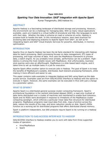
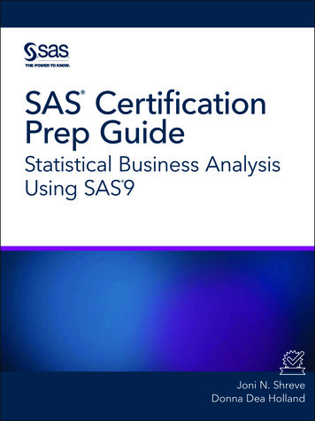
SAS is an evolution of the parallel SCSI device interface into a serial point-to-point interface. SASphysical links (phys) are a set of four wires used as two differential signal pairs. One differential signaltransmits in one direction, while the other differential signal transmits in the opposite direction. Data canbe transmitted in both directions simultaneously. Phys are contained in SAS ports which contain one ormore phys. A port is a wide port if there are more than one phy in the port. If there is only one phy inthe port, it is a narrow port. A port is identified by a unique SAS worldwide name (also called SASaddress).A SAS controller contains one or more SAS ports. A path is a logical point-to-point link between a SASinitiator port in the controller and a SAS target port in the I/O device (for example a disk). A connectionis a temporary association between a controller and an I/O device through a path. A connection enablescommunication to a device. The controller can communicate to the I/O device over this connection byusing either the SCSI command set or the ATA/ATAPI command set depending on the device type.A SAS expander enables connections between a controller port and multiple I/O device ports by routingconnections between the expander ports. Only a single connection through an expander can exist at anygiven time. Using expanders creates more nodes in the path from the controller to the I/O device. If anI/O device supports multiple ports, more than one path to the device can exist when there are expanderdevices included in the path.A SAS fabric refers to the summation of all paths between all SAS controller ports and all I/O deviceports in the SAS subsystem including cables, enclosures, and expanders.The following example SAS subsystem shows some of the concepts described in this SAS overview. Acontroller is shown with eight SAS phys. Four of those phys are connected into two different wide ports.One connector contains four phys grouped into two ports. The connectors have no significance in SASother than causing a physical wire connection. The four-phy connector can contain between one and fourports depending on the type of cabling that is used. The uppermost port in the figure shows acontroller-wide port number 6 that consists of phy numbers 6 and 7. Port 6 connects to an expander,which attaches to one of the dual ports of the I/O devices. The dashed red line indicates a path betweenthe controller and an I/O device. Another path runs from the controller’s port number 4 to the other portof the I/O device. These two paths provide two different possible connections for increased reliability byusing redundant controller ports, expanders, and I/O device ports. The SCSI Enclosure Services (SES) is acomponent of each expander.Figure 10. Example SAS SubsystemChapter 1. SAS RAID controllers for AIX overview9
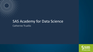
Disk arraysDisk arrays are groups of disks that work together with a specialized array controller to take advantageof potentially higher data transfer rates and, depending on the RAID level selected, data redundancy.Disk arrays use RAID technology to offer data redundancy and improved data transfer rates over thoseprovided by single large disks. If a disk failure occurs, the disk can usually be replaced withoutinterrupting normal system operation.Data redundancyThe disk array controller keeps track of how the data is distributed across the disks. RAID 5, 6, and 10disk arrays also provide data redundancy, so that no data is lost if a single disk in the array fails. If adisk failure occurs, the disk can usually be replaced without interrupting normal system operation.Using arraysEach disk array can be used by AIX in the same way as it would a single non-RAID disk. For example,after creating a disk array, you can create a file system on the disk array or use AIX commands to makethe disk array available to the system by adding the disk array to a volume group.hdiskLike other disk storage units in AIX, the disk arrays are assigned names using the hdisk form. The namesare deleted when you delete the disk array. An hdisk is a disk that is formatted to 512 bytes per sector.These disks must be formatted to 528 bytes per sector before they can be used in disk arrays.pdiskThe individual physical disks that comprise disk arrays (or serve as candidates to be used in disk arrays)are represented by pdisk names. A pdisk is a disk that is formatted to 528 bytes per sector.Array managementThe IBM SAS RAID controller is managed by the IBM SAS Disk Array Manager. The disk array managerserves as the interface to the controller and I/O device configuration. It is also responsible for themonitoring and recovery features of the controller.Boot deviceIf a disk array is to be used as the boot device, you might have to prepare the disks by booting from theIBM server hardware stand-alone diagnostics CD and creating the disk array before installing AIX. Youmight want to perform this procedure when the original boot drive is to be used as part of a disk array.Array configurationThe following figure illustrates a possible disk array configuration.10
Figure 11. Disk array configurationThe List SAS Disk Array Configuration option in the disk array manager can be used to display thepdisk and hdisk names, their associated location codes, and their current state of operation. Thefollowing sample output is displayed when the List SAS Disk Array Configuration option is invoked. ------------------------------ --------------------- NameResource StateDescriptionSize --------------------- sissas0FFFFFFFF PrimaryPCI-X266 Planar 3 Gb SAS Adapter hdisk800FF0100 OptimalRAID 6 Array69.6GB pdisk000040100 ActiveArray Member34.8GB pdisk200040B00 ActiveArray Member34.8GB pdisk800000500 ActiveArray Member34.8GB pdisk900000A00 ActiveArray Member34.8GB hdisk700FF0000 OptimalRAID 0 Array34.8GB pdisk400040000 ActiveArray Member34.8GB hdisk1300FF0300 OptimalRAID 0 Array34.8GB pdisk500040300 ActiveArray Member34.8GB hdisk1400FF0400 FailedRAID 0 Array34.8GB pdisk300040A00 FailedArray Member34.8GB hdisk000040500 AvailableSAS Disk Drive146.8GB hdisk100040600 AvailableSAS Disk Drive146.8GB hdisk300000600 AvailableSAS Disk Drive73.4GB ------------------------------ Chapter 1. SAS RAID controllers for AIX overview11
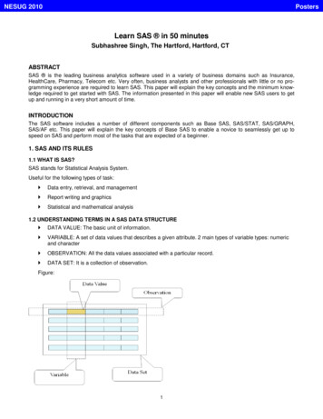
Related tasks“Preparing disks for use in SAS disk arrays” on page 26Use this information to prepare disks for use in an array.“Viewing the disk array configuration” on page 29Use this procedure to view SAS disk array configurations on your server.Supported RAID levelsThe RAID level of a disk array determines how data is stored on the disk array and the level ofprotection that is provided.If a part of the RAID system fails, different RAID levels help to recover lost data in different ways. Withthe exception of RAID level 0, if a single drive fails within an array, the array controller can reconstructthe data for the Failed disk by using the data stored on other hard drives within the array. This datareconstruction has little or no impact to current system programs and users. The controller supportsRAID levels 0, 5, 6, and 10. Not all controllers support all RAID levels. Each RAID level supported by thecontroller has its own attributes and uses a different method of writing data. The following informationprovides details for each supported RAID level.Related concepts“PCI-X SAS RAID card comparison” on page 1This table compares the main features of PCI-X SAS RAID cards.“PCIe SAS RAID card comparison” on page 5This table compares the main features of PCI Express (PCIe) SAS RAID cards.RAID 0Learn how data is written to a RAID 0 array.RAID 0 stripes data across the disks in the array, for optimal performance. For a RAID 0 array of threedisks, data would be written in the following pattern.Figure 12. RAID 0RAID 0 offers a high potential I/O rate, but it is a nonredundant configuration. As a result, there is nodata redundancy available for the purpose of reconstructing data in the event of a disk failure. There isno error recovery beyond what is normally provided on a single disk. Unlike other RAID levels, the array12
controller never marks a RAID 0 array as Degraded as the result of a disk failure. If a physical disk failsin a RAID 0 disk array, the disk array is marked as Failed. All data in the array must be backed upregularly to protect against data loss.RAID 5Learn how data is written to a RAID 5 array.RAID 5 stripes data across all disks in the array. RAID level 5 also writes array parity data. The paritydata is spread across all the disks. For a RAID 5 array of three disks, array data and parity informationare written in the following pattern:Figure 13. RAID 5If a disk fails in a RAID 5 array, you can continue to use the array normally. A RAID 5 array operatingwith a single Failed disk is said to be operating in Degraded mode. Whenever data is read from aDegraded disk array, the array controller recalculates the data on the Failed disk by using data and parityblocks on the operational disks. If a second disk fails, the array will be placed in the Failed state and willnot be accessible.Related concepts“Stripe-unit size” on page 16With RAID technology, data is striped across an array of physical disks. This data distribution schemecomplements the way that the operating system requests data.RAID 6Learn how data is written to a RAID 6 array.RAID 6 stripes data across all disks in the array. RAID level 6 also writes array ″P″ and ″Q″ parity data.The P and Q parity data, is spread across all the disks. For a RAID 6 array of four disks, array data andparity information are written in the following pattern:Chapter 1. SAS RAID controllers for AIX overview13
Figure 14. RAID 6If
Chapter 1. SAS RAID controllers for AIX overview Find usage and maintenance information regarding controllers for the serial-attached SCSI (SAS) Redundant Array of Independent Disks (RAID) for the AIX operating system. Use this information in conjunction with your specific system unit and operating system documentation. General information is