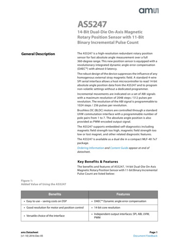
Transcription
SPI – Universal Serial Communication Interface SPI Mode
Serial Peripheral Interface (SPI) is not really a protocol, but more of a general idea. It’sthe bare-minimum way to transfer a lot of data between two chips as quickly aspossible,WHAT IS SPI?The core idea of SPI is that each device has ashift-register that it can use to send orreceive a byte of data.These two shift registers are connectedtogether in a ring, the output of one going to theinput of the other and vice-versa.One device, the master,controls the commonclock signal that makes sure that each registershifts one bit in just exactly as the other isshifting one bit out (and vice-versa). It’s hard toget simpler than -wrong-spi/
It’s this simplicity that makes SPI fast. While asynchronous serialcommunications can run in the hundred-of-thousands of bits persecond, SPI is usually good for ten megabits per second or more.You often see asynchronous serial between man and machine,because people are fairly slow. But between machine andmachine, it’s going to be SPI or I2C.Turning this pair of shiftregisters into a fullblown data bus involvesa couple more wires
To begin communication, the master configures the clock, using a frequency supported bythe slave device, typically up to a few MHz. The master then selects the slave device with alogic level 0 on the chip select line. If a waiting period is required, such as for an analog-todigital conversion, the master must wait for at least that period of time before issuing clockcycles.During each SPI clock cycle, a full duplex data transmission occurs. The master sends a biton the MOSI line and the slave reads it, while the slave sends a bit on the MISO line and themaster reads it. This sequence is maintained even when only one-directional data transfer isintended.
The master controls the clock (CLK or SCK) line, that’s shared among all of the devices onthe bus. Instead of a simple ring as drawn above, the master’s shift register is effectivelyin a ring with each of the slave devices, and the lines making up this ring are labelledMISO (“master-in, slave-out”) and MOSI (“master-out, slave-in”) depending on thedirection of data flow.Since all of the rings are shared, each slavehas an additional dedicated line that tells itwhen to attach and detach from the bus.Each slave has a slave-select (SS orsometimes called chip-select CS) line, andwhen it’s high, the slave disconnects itsMISO line, and ignores what comes in overMOSI.When the individual SS line is pulled low, theslave engages. Note that the master isresponsible for keeping one and only one SSlineactive low at any given time.
Typical SPI Communication:1. The master pulls the slave’s personal slave-select line low, at whichpoint the slave wakes up, starts listening, and connects to the MISOline. Depending on the phase both chips may also set up their first bitof output
2. The master sends the first clock pulse and the first bit of data moves frommaster to slave (along MOSI) and from slave to master (along MISO).
3. The master keeps cycling the clock, bits are traded, and after eight bits,both sides read in the received data and queue up the next byte fortransmission.Address CommandData
3. The master keeps cycling the clock, bits are traded, and after eightbits, both sides read in the received data and queue up the next byte fortransmission.4. After a number of bytes are traded this way, the master again drivesthe SS line high and the slave disengages.
SPEEDBecause SPI is clocked, and the slave-select line delimits a conversation, there’s notmuch that can go wrong in syncronize the two devices.Not much, except when the master talks too fast for the slave to follow. The goodnews? This is easy to debug.For debugging purposes, there’s nothing to lose by going slow. Nearly every chip thatcan handle SPI data at 10 MHz can handle it at 100 kHz as well.On the other hand, due to all sorts of real-world issues with voltages propagating fromone side of a wire to another and the chip’s ability to push current into the wire toovercome its parasitic capacitance, the maximum speed at which your system can runis variable.For really high SPI speeds (say, 10 MHz and above?) your system design may be thelimiting factor.
Find Arduino code:Convert Loop to Timer functionsReplace calls to library which is not interrupt able or locally codedUse RT ADC3 as work horse – 10 interrupts per second – replace Loop:Analyze library functions used
Original Arduino Code – library functions used
SetUpSPI functions used:begin()setDataMode()GPIO pin used for Chip SelectpinMode(CS, OUTPUT)digitalWrite(CS, HIGH/LOW)
Replace loop: with TimerA0 A3 CCR0 interrupts (10/second)Serial.print is replaced with sprintf() and UARTPrint() functions
digitalWrite changes CS output pin HIGH/LOWSPI.transfer(value) both input/output the SPI transfers
SAME THING:digitalWrite changes CS output pin HIGH/LOWSPI.transfer(value) both input/output the SPI transfers
SPI is always two directions.When you send, you also receive, and to receive, you have to send.In your code, when you send the command, you’ll receive a dummy answer while you’resending the command. While the bits of the commands are sent (and the slave hasn’treceived the command), the SPI hardware is already ‘receiving’ bits simultaneously.So once the command byte has been sent, a byte has been received too,which you’ll need to discard.THEN you send one or two dummy bytes and while they’re sent, you’re receiving the 8 or16 bit answer.My code does not use TXISR to interrupt, because this two-way transfer is for 6 bytesonly. Code in the next Module can show way to start one byte and enter low power modeto wait for that byte to be sent.So the MSP430 routines here just poll until the TX is complete and then sends/receivesthe next ‘transfer’ byte
sketch SPI ADXL345.ino
SetUp
SPI SetUp
Timer setup - 10/second
Timer ISR – This is where Loop Tasks go
UART Print the string
UART SetUp and UARTPutString
SPI Transfer – Polled method
Chip Select and writeRegister for ADXL345 SPI
Chip Select and readRegister for ADXL345 SPI
received the command), the SPI hardware is already 'receiving' bits simultaneously. So once the command byte has been sent, a byte has been received too, which you'll need to discard. THEN you send one or two dummy bytes and while they're sent, you're receiving the 8 or 16 bit answer.