Transcription
Serial Peripheral Interface (SPI) alearn.sparkfun.com tutorialAvailable online at: http://sfe.io/t16ContentsIntroductionWhat's Wrong with Serial Ports?A Synchronous SolutionReceiving DataChip Select (CS)Programming for SPIResources and Going FurtherIntroductionSerial Peripheral Interface (SPI) is an interface bus commonly used to send data betweenmicrocontrollers and small peripherals such as shift registers, sensors, and SD cards. It usesseparate clock and data lines, along with a select line to choose the device you wish to talk to.Suggested ReadingStuff that would be helpful to know before reading this tutorial:Serial CommunicationAsynchronous serial communication concepts: packets, signal levels, baud rates, UARTs and more!Favorited Favorite 98BinaryBinary is the numeral system of electronics and programming.so it must be important to learn. But,what is binary? How does it translate to other numeral systems like decimal?Favorited Favorite 48Shift RegistersAn introduction to shift registers and potential uses.Favorited Favorite 44Logic LevelsPage 1 of 11
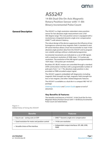
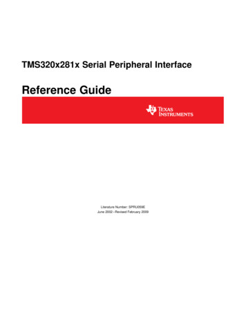
Learn the difference between 3.3V and 5V devices and logic levels.Favorited Favorite 79What's Wrong with Serial Ports?A common serial port, the kind with TX and RX lines, is called "asynchronous" (not synchronous)because there is no control over when data is sent or any guarantee that both sides are running atprecisely the same rate. Since computers normally rely on everything being synchronized to asingle “clock” (the main crystal attached to a computer that drives everything), this can be a problemwhen two systems with slightly different clocks try to communicate with each other.To work around this problem, asynchronous serial connections add extra start and stop bits to eachbyte help the receiver sync up to data as it arrives. Both sides must also agree on the transmissionspeed (such as 9600 bits per second) in advance. Slight differences in the transmission rate aren'ta problem because the receiver re-syncs at the start of each byte.(By the way, if you noticed that "11001010" does not equal 0x53 in the above diagram, kudos toyour attention to detail. Serial protocols will often send the least significant bits first, so the smallestbit is on the far left. The lower nybble is actually 0011 0x3, and the upper nybble is 0101 0x5.)Asynchronous serial works just fine, but has a lot of overhead in both the extra start and stop bitssent with every byte, and the complex hardware required to send and receive data. And as you'veprobably noticed in your own projects, if both sides aren't set to the same speed, the received datawill be garbage. This is because the receiver is sampling the bits at very specific times (the arrowsin the above diagram). If the receiver is looking at the wrong times, it will see the wrong bits.A Synchronous SolutionSPI works in a slightly different manner. It's a "synchronous" data bus, which means that it usesseparate lines for data and a "clock" that keeps both sides in perfect sync. The clock is anoscillating signal that tells the receiver exactly when to sample the bits on the data line. This couldbe the rising (low to high) or falling (high to low) edge of the clock signal; the datasheet will specifywhich one to use. When the receiver detects that edge, it will immediately look at the data line toread the next bit (see the arrows in the below diagram). Because the clock is sent along with thedata, specifying the speed isn't important, although devices will have a top speed at which they canoperate (We'll discuss choosing the proper clock edge and speed in a bit).Page 2 of 11
One reason that SPI is so popular is that the receiving hardware can be a simpleshift register. Thisis a much simpler (and cheaper!) piece of hardware than the full-up UART (Universal AsynchronousReceiver / Transmitter) that asynchronous serial requires.Receiving DataNote: You may not recognize the COPI/CIPO labels for SPI pins. SparkFun has joined with othermembers of OSHWA in a resolution to move away from using "Master" and "Slave" to describesignals between the controller and the peripheral. Check out this page for more on our reasoningbehind this change. You can also see OSHWA's resolution here.You might be thinking to yourself, self, that sounds great for one-way communications, but how doyou send data back in the opposite direction? Here's where things get slightly more complicated.In SPI, only one side generates the clock signal (usually called CLK or SCK for Serial ClocK). Theside that generates the clock is called the "controller", and the other side is called the "peripheral".There is always only one controller (which is almost always your microcontroller), but there can bemultiple peripherals (more on this in a bit).When data is sent from the controller to a peripheral, it's sent on a data line called COPI, for"Controller Out / Peripheral In". If the peripheral needs to send a response back to the controller,the controller will continue to generate a prearranged number of clock cycles, and the peripheralwill put the data onto a third data line called CIPO, for "Controller In / Peripheral Out".Page 3 of 11
Notice we said "prearranged" in the above description. Because the controller always generates theclock signal, it must know in advance when a peripheral needs to return data and how much datawill be returned. This is very different than asynchronous serial, where random amounts of data canbe sent in either direction at any time. In practice this isn't a problem, as SPI is generally used totalk to sensors that have a very specific command structure. For example, if you send the commandfor "read data" to a device, you know that the device will always send you, for example, two bytes inreturn. (In cases where you might want to return a variable amount of data, you could always returnone or two bytes specifying the length of the data and then have the controller retrieve the fullamount.)Note that SPI is "full duplex" (has separate send and receive lines), and, thus, in certain situations,you can transmit and receive data at the same time (for example, requesting a new sensor readingwhile retrieving the data from the previous one). Your device's datasheet will tell you if this ispossible.Chip Select (CS)There's one last line you should be aware of, called CS for Chip Select. This tells the peripheral thatit should wake up and receive / send data and is also used when multiple peripherals are present toselect the one you'd like to talk to.Page 4 of 11
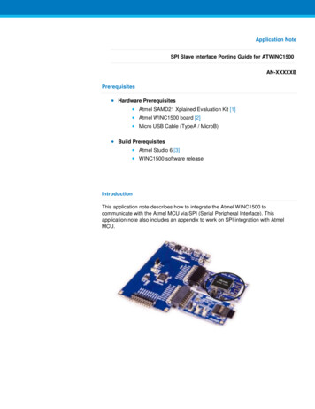
The CS line is normally held high, which disconnects the peripheral from the SPI bus. (This type oflogic is known as “active low,” and you’ll often see used it for enable and reset lines.) Just beforedata is sent to the peripheral, the line is brought low, which activates the peripheral. When you'redone using the peripheral, the line is made high again. In a shift register, this corresponds to the"latch" input, which transfers the received data to the output lines.Multiple peripheralsThere are two ways of connecting multiple peripherals to an SPI bus:1. In general, each peripheral will need a separate CS line. To talk to a particular peripheral,you'll make that peripheral's CS line low and keep the rest of them high (you don't want twoperipherals activated at the same time, or they may both try to talk on the same CIPO lineresulting in garbled data). Lots of peripherals will require lots of CS lines; if you're running lowon outputs, there are binary decoder chips that can multiply your CS outputs.Page 5 of 11
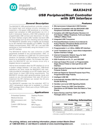
2. On the other hand, some parts prefer to be daisy-chained together, with the CIPO (output) ofone going to the COPI (input) of the next. In this case, a single CS line goes to all theperipherals. Once all the data is sent, the CS line is raised, which causes all the chips to beactivated simultaneously. This is often used for daisy-chained shift registers and addressableLED drivers.Note that, for this layout, data overflows from one peripheral to the next, so to send data to anyoneperipheral, you'll need to transmit enough data to reach all of them. Also, keep in mind that the firstpiece of data you transmit will end up in the last peripheral.This type of layout is typically used in output-only situations, such as driving LEDs where you don'tneed to receive any data back. In these cases you can leave the controller's CIPO linedisconnected. However, if data does need to be returned to the controller, you can do this byclosing the daisy-chain loop (blue wire in the above diagram). Note that if you do this, the returndata from peripheral 1 will need to pass through all the peripherals before getting back to thecontroller, so be sure to send enough receive commands to get the data you need.Programming for SPIMany microcontrollers have built-in SPI peripherals that handle all the details of sending andPage 6 of 11
receiving data, and can do so at very high speeds. The SPI protocol is also simple enough that you(yes, you!) can write your own routines to manipulate the I/O lines in the proper sequence totransfer data. (A good example is on the Wikipedia SPI page.)If you're using an Arduino, there are two ways you can communicate with SPI devices:1. You can use the shiftIn() and shiftOut() commands. These are software-based commands thatwill work on any group of pins, but will be somewhat slow.2. Or you can use the SPI Library, which takes advantage of the SPI hardware built into themicrocontroller. This is vastly faster than the above commands, but it will only work on certainpins.You will need to select some options when setting up your interface. These options must matchthose of the device you're talking to; check the device's datasheet to see what it requires.The interface can send data with the most-significant bit (MSB) first, or least-significant bit(LSB) first. In the Arduino SPI library, this is controlled by the setBitOrder() function.The peripheral will read the data on either the rising edge or the falling edge of the clockpulse. Additionally, the clock can be considered "idle" when it is high or low. In the ArduinoSPI library, both of these options are controlled by the setDataMode() function.SPI can operate at extremely high speeds (millions of bytes per second), which may be toofast for some devices. To accommodate such devices, you can adjust the data rate. In theArduino SPI library, the speed is set by the setClockDivider() function, which divides thecontroller clock (16MHz on most Arduinos) down to a frequency between 8MHz (/2) and125kHz (/128).If you're using the SPI Library, you must use the provided SCK, COPI and CIPO pins, as thehardware is hardwired to those pins. There is also a dedicated CS pin that you can use (whichmust, at least, be set to an output in order for the SPI hardware to function), but note that youcan use any other available output pin(s) for CS to your peripheral device(s) as well.On older Arduinos, you'll need to control the CS pin(s) yourself, making one of them lowbefore your data transfer and high afterward. Newer Arduinos such as the Due can controleach CS pin automatically as part of the data transfer; see the Due SPI documentation pagefor more information.Interested in learning more foundational topics?See our Engineering Essentials page for a full list of cornerstone topics surrounding electricalengineering.Take me there!Page 7 of 11
Resources and Going FurtherTips and TricksBecause of the high speed signals, SPI should only be used to send data over shortdistances (up to a few feet). If you need to send data further than that, lower the clock speed,and consider using specialized driver chips.If things aren't working the way you think they should, a logic analyzer is a very helpful tool.Smart analyzers like the Saleae USB Logic Analyzer can even decode the data bytes for adisplay or logging.Page 8 of 11
Advantages of SPI:It's faster than asynchronous serialThe receive hardware can be a simple shift registerIt supports multiple peripheralsDisadvantages of SPI:It requires more signal lines (wires) than other communications methodsThe communications must be well-defined in advance (you can't send random amounts ofdata whenever you want)The controller must control all communications (peripherals can't talk directly to each other)It usually requires separate CS lines to each peripheral, which can be problematic if numerousPage 9 of 11
peripherals are needed.Further ReadingCheck out the Wikipedia page on SPI, which includes lots of good information on SPI and othersynchronous interfaces.This page presents a more correct way to set up an SPI network amongst your embedded devices,particularly for use with an Arduino microcontroller.A number of SparkFun products have SPI interfaces. For example, theBar Graph Breakout kit hasan easy-to-use SPI interface that you can use to turn any of 30 LEDs on or off.Other communication options:Serial CommunicationAsynchronous serial communication concepts: packets, signal levels, baud rates, UARTs and more!Favorited Favorite 98Analog to Digital ConversionThe world is analog. Use analog to digital conversion to help digital devices interpret the world.Favorited Favorite 55I2CAn introduction to I2C, one of the main embedded communications protocols in use today.Favorited Favorite 122AST-CAN485 Hookup GuideThe AST CAN485 is a miniature Arduino in the compact form factor of the ProMini. In addition to allthe usual features it has on-board CAN and RS485 ports enabling quick and easy interfacing to amultitude of industrial devices.Favorited Favorite 10Now that you’re a pro on SPI, here are some other tutorials to practice your new skills:MP3 Player Shield Music BoxMusic Box Project based on the Dr. Who TARDIS.Favorited Favorite 8Using the Serial 7-Segment DisplayHow to quickly and easily set up the Serial 7-Segment Display and the Serial 7-Segment DisplayPage 10 of 11
Shield.Favorited Favorite 14SparkFun BME280 Breakout Hookup GuideA guide for connecting the BME280 sensor to a microcontroller, and for using the SparkFunArduino library.Favorited Favorite 0Raspberry Pi SPI and I2C TutorialLearn how to use serial I2C and SPI buses on your Raspberry Pi using the wiringPi I/O library forC/C and spidev/smbus for Python.Favorited Favorite 23learn.sparkfun.com CC BY-SA 3.0 SparkFun Electronics Niwot, ColoradoPage 11 of 11
receiving data, and can do so at very high speeds. The SPI protocol is also simple enough that you (yes, you!) can write your own routines to manipulate the I/O lines in the proper sequence to transfer data. (A good example is on the Wikipedia SPI page.) If you're using an Arduino, there are two ways you can communicate with SPI devices: 1.