Transcription
SPI StormData sheetRevision 1.02 - February 2015
SPI StormData sheetTable of Contents1 Main features. 42 SPI Storm Overview. 42.1 SPI Storm at a glance. 42.2 Minimum Host PC requirements. 52.3 Operating power. 52.4 USB and system interface connections. 53 SPI Storm I/O connector. 64 DC and Switching Characteristics . 74.1 Absolute maximum ratings. 74.2 Recommended operating conditions. 74.3 System Characteristics and Performance. 84.4 Switching Characteristics. 9Table of TablesTableTableTableTableTableTable1 : SPI Storm I/O connector details.62: Absolute maximum ratings.73: Recommended operating conditions.74: System characteristics.85: Clock frequencies, rise and fall time and skews.96: SPI Storm timing parameters.9Table of FiguresFigureFigureFigureFigureFigure1:2:3:4:5:SPI Storm - Overview.4System connector external power supply pins .5SPI Storm I/O connector ports.6User I/O input threshold voltage vs external supply voltage.8Skew between SCLK and the output lines, with clock ratio equal to 1.9Revision 1.02 - February 2015www.byteparadigm.com2/9
SPI StormData sheetReferences[]Revision historyVersion1.001.01DateApril 2011December 2011Revision 1.02 - February 2015DescriptionDocument creationAdded device physical dimensionswww.byteparadigm.com3/9
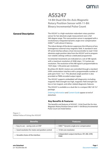
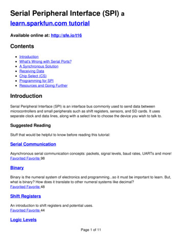
SPI StormData sheet1 Main features High-speed USB 2.0 host interface (full-speed 12 Mbps and high-speed 480 Mbps)SPI (Serial Peripheral Interface) Host Adapter on 3- and 4- wiresDual- and Quad- SPI Host AdapterCustom protocol supportGPO (General-Purpose Output) port for additional arbitrary digital signal generation (8-bit digitalpattern generator)Up to 100 MHz operationUSB-powered and controlledSelectable internal (USB bus) or external power supply for I/Os voltagesSystem interface operating from 1.25 V to 3.3VOpen-drain I/O supportDelivered with the SPI Storm Studio(TM) including: documentation, drivers and host control software(MS-Windows XP / MS-Windows 7, 32-bit and 64-bit)32 MB total internal memory2 SPI Storm Overview2.1 SPI Storm at a glanceByte Paradigm’s SPI Storm is a high-speed Serial Protocol Host Adapter used for chips and electronicboard stimulation with serial protocols and digital patterns.It operates on standard SPI protocol, Dual-SPI, Quad-SPI and custom serial protocol interfaces including3 wires interfaces with bidirectional data lines, up to 100 MHz operation. SPI Storm also supports opendrain output signalling.SPI Storm is delivered with SPI Storm Studio(TM) control software with graphical user interface anddirect C/C DLL access.Figure 1:SPI Storm - OverviewI/O connectorAbsolute maximum ratings & recommendedoperating conditions information labelI/O external voltage supplyconnector (protected with ajumper)I/O connector information labelUSB connectorDevice dimensions (WxLxH) : 55 x 80 x 16 mmRevision 1.02 - February 2015www.byteparadigm.com4/9
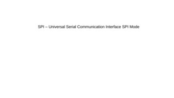
SPI StormData sheet2.2 Minimum Host PC requirementsSPI Storm connects to any PC using Microsoft Windows XP or Windows 7 operating systems (32-bit/64bit) through a USB 2.0 port connector.NET 4.0 or .NET 4.0 (or a more recent version) client profile framework must be installed – .aspx?FamilyID e5ad0459-cbcc-4b4f-97b6fb17111cf5442.3 Operating powerThe main power supply of the SPI Storm device is taken from the USB bus to provide the necessaryvoltage to the device core. By default, the I/O voltage standard is 3.3V LVCMOS.To use a different voltage standard for the I/O, the jumper located on the I/O external voltage supplyconnector must be removed and an external voltage source must be applied on this connector. Externalvoltage level must be between 1.25V and 3.3V.The external power supply connector is located at the side of the device. It is protected with a jumper.This power connector is labelled “GND VEXT”. ! Respect the connector polarity !Figure 2:System connector external power supply pinsVEXT connector locationGND pinVEXT (positive voltage) pin2.4 USB and system interface connectionsA USB mini-B to USB type A cable is provided with the SPI Storm device.A set of 34 flying lead wires connect the SPI Storm device to the board under test. A standard pinheader with 2.54 mm (0.1 inch) pitch must be foreseen on the target board where access is desired.Revision 1.02 - February 2015www.byteparadigm.com5/9
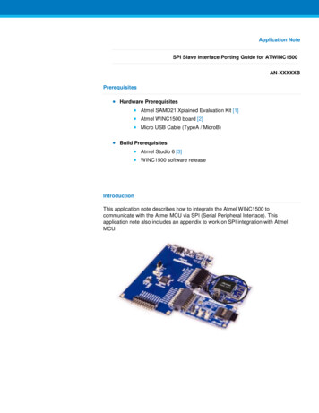
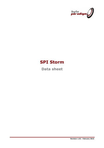
SPI StormData sheet3 SPI Storm I/O connectorPORTS: CLOCK PORT : CKI clock input for external reference clock; CKO: reserved for future use.SERIAL PORT: used for interfacing slaves with standard SPI protocols, dual- and quad-SPIprotocols and custom serial protocols;GPO PORT: used as a 8-bit arbitrary digital pattern generator;TRIGGER PORT: up to 8 bits usable as trigger input signals for the SERIAL and the GPO portsFigure 3:SPI Storm I/O connector portsCLOCKPORTSERIALPORTGPOportTRIGGERPORTThe other pins are ground pins ('GND') and cannot be used for functional signalling. Ground pins must beconnected to the ground of the system under test for proper operation.Table 1 : SPI Storm I/O connector detailsPin nameCKOCKISCLKMOSI n 1.02 - February 2015Description / OptionsCLOCK PORTReserved for future useInput used to supply an external reference clock signal.SERIAL PORTSerial clockMulti-purpose I/O used as data line for serial protocols and dual- / quad'serial' protocols. Used as MOSI (Master Out Slave In) signal for standardSPI (Serial Peripheral Interface) protocol.www.byteparadigm.com6/9
SPI StormData sheetPin nameMISO (DQ1)WEDirectionIn/Out/InoutOutputSS0SS1SS2 (DQ2)SS3 (DQ3)OutputOutputIn/Out/InoutIn/Out/InoutQ0 . Q7OutputD0 D7InputDescription / OptionsMulti-purpose I/O used as data line for serial protocols and dual- / quad'serial' protocols. Used as MISO (Master In Slave Out) signal for standardSPI (Serial Peripheral Interface) protocol.Used to indicate the direction of the bus for bi-directional SPI (SerialPeripheral Interface) protocol on 3 wires ('SPI-3').Used as 'Slave Select' output for standard SPI (Serial Peripheral Interface)protocolsMulti-purpose I/O used as data line for quad- 'serial' protocolsMulti-purpose I/O used as data line for quad- 'serial' protocolsGPO PORT8-bit 'General-Purpose Output' port. Used to apply arbitrary output data.TRIGGER PORT8-bit input port used as trigger for the SERIAL and the GPO ports.4 DC and Switching Characteristics4.1 Absolute maximum ratingsTable 2:SymbolVEXTVINVINAbsolute maximum ratingsDescriptionExternal DC supply voltage relative to GNDVoltage applied to any user I/O pins relativeto GNDVoltage applied to any user I/O pins relativeto GNDConditionsVCCO2 VINTMin-0.5-0.5Max 3.75 3.75UnitVVVCCO2 VEXT-0.5VCCO 0.5VNotes:1. Stresses beyond those listed under Absolute Maximum Ratings may cause permanent damage to thedevice. These are stress ratings only. Functional operation of the device at these or any otherconditions beyond those listed under the Recommended Operating Conditions is not implied. Exposureto Absolute Maximum Ratings conditions for extended periods of time adversely affects devicereliability.2. Vcco is the supply voltage of the I/O pin output driver. It can be supplied internally (VINT) orexternally (VEXT), through the external connector.4.2 Recommended operating conditionsTable nded operating conditionsDescriptionExternal DC supply voltage relative to GNDQuiescent supply current for any user I/Opin.Total quiescent current for all user I/Oused simultaneouslyTotal quiescent current for all user I/Oused simultaneouslyOperating ambient temperatureLogic high voltage thresholdLogic low voltage thresholdRevision 1.02 - February 2015I/O voltage 1,38 V1.25 V I/O voltage 1.38 VVCCO2 VINTMin 1.251-Max 3.386120UnitVmAmAmAVCCO2 VEXT-300mAVCCO2 VINTVCCO2 VINT02.0-450.8 CVVwww.byteparadigm.com7/9
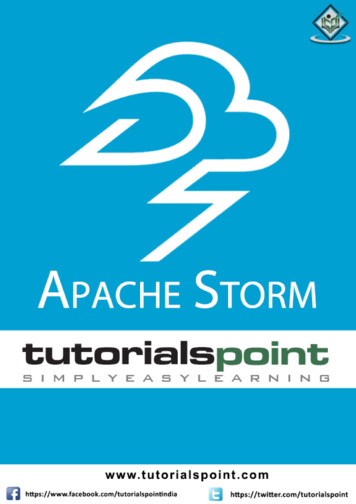
SPI StormData sheetNotes:1. This is an absolute minimum. The supply noise and accuracy must be taken into account whenapplying external voltage to the device. For example, if the accuracy of the supply is 5%, the providedlevel should be 1.25/0.95 1.316V.2. Vcco is the supply voltage of the I/O pin output driver. It can be supplied internally (VINT) orexternally (VEXT), through the external connector.3. Refer to Figure 4 for the VIH and VIL threshold voltage when the external supply voltage is selected.Figure 4:User I/O input threshold voltage vs external supply voltage2,5VIH min, VIL max (V)21,5VIH minVIL max10,5011,522,533,5External Supply Voltage (V)4.3 System Characteristics and PerformanceTable 4:System characteristicsDescriptionUSB 2.0 interface total throughputUSB 2.0 interface useful throughput for dataUser I/O operating frequencyInternal memory bufferRevision 1.02 - February UnitMbpsMByte/sMByte/sMHzMByte8/9
SPI StormData sheet4.4 Switching CharacteristicsTable 5:SymbolSCLKtskwtlhthlClock frequencies, rise and fall time and skewsDescriptionOutput clock frequencyConditionsSkew between SCLK and data linesOutput pin rise timeOutput pin fall timeRevision 1.02 - February 2015VCCO 3.3VVCCO 2.5VVCCO 1.8VVCCO 1.5VVCCO 1.25VVCCO 3.3VVCCO 2.5VVCCO 1.8VVCCO 1.5VVCCO 1.25Vwww.byteparadigm.comMin98 kHzTyp-Max100 50010001000100014001500pspspspspspspspspsps9/9
Byte Paradigm's SPI Storm is a high-speed Serial Protocol Host Adapter used for chips and electronic board stimulation with serial protocols and digital patterns. It operates on standard SPI protocol, Dual-SPI, Quad-SPI and custom serial protocol interfaces including 3 wires interfaces with bidirectional data lines, up to 100 MHz operation.