Transcription
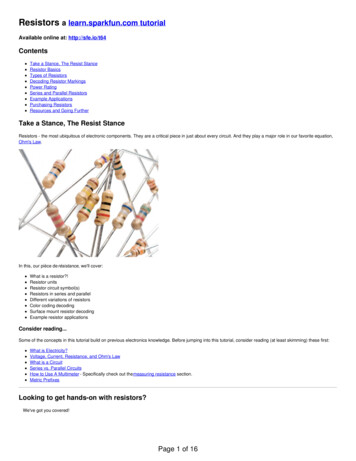
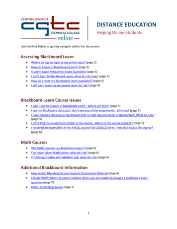
Serial Communication a learn.sparkfun.comtutorialAvailable online at: http://sfe.io/t8ContentsIntroductionRules of SerialWiring and HardwareUARTsCommon PitfallsResources and Going FurtherIntroductionEmbedded electronics is all about interlinking circuits (processors or other integrated circuits) tocreate a symbiotic system. In order for those individual circuits to swap their information, they mustshare a common communication protocol. Hundreds of communication protocols have been definedto achieve this data exchange, and, in general, each can be separated into one of two categories:parallel or serial.Parallel vs. SerialParallel interfaces transfer multiple bits at the same time. They usually requirebuses of data transmitting across eight, sixteen, or more wires. Data is transferred in huge, crashing waves of 1'sand 0's.Page 1 of 16
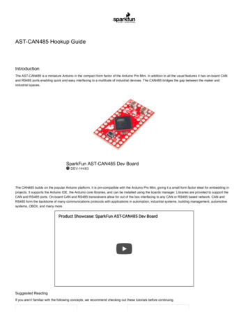
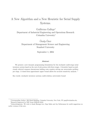
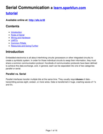
An 8-bit data bus, controlled by a clock, transmitting a byte every clock pulse. 9 wires are used.Serial interfaces stream their data, one single bit at a time. These interfaces can operate on as littleas one wire, usually never more than four.Example of a serial interface, transmitting one bit every clock pulse. Just 2 wires required!Think of the two interfaces as a stream of cars: a parallel interface would be the 8 lane megahighway, while a serial interface is more like a two-lane rural country road. Over a set amount oftime, the mega-highway potentially gets more people to their destinations, but that rural two-lanerserves its purpose and costs a fraction of the funds to build.Parallel communication certainly has its benefits. It's fast, straightforward, and relatively easy toimplement. But it requires many more input/output (I/O) lines. If you've ever had to move a projectfrom a basic Arduino Uno to a Mega, you know that the I/O lines on a microprocessor can beprecious and few. So, we often opt for serial communication, sacrificing potential speed for pin realPage 2 of 16
estate.Asynchronous SerialOver the years, dozens of serial protocols have been crafted to meet particular needs of embeddedsystems. USB (universal serial bus), and Ethernet, are a couple of the more well-known computingserial interfaces. Other very common serial interfaces include SPI, I2C, and the serial standardwe're here to talk about today. Each of these serial interfaces can be sorted into one of two groups:synchronous or asynchronous.A synchronous serial interface always pairs its data line(s) with a clock signal, so all devices on asynchronous serial bus share a common clock. This makes for a more straightforward, often fasterserial transfer, but it also requires at least one extra wire between communicating devices.Examples of synchronous interfaces include SPI, and I 2C.Asynchronous means that data is transferred without support from an external clock signal.This transmission method is perfect for minimizing the required wires and I/O pins, but it does meanwe need to put some extra effort into reliably transferring and receiving data. The serial protocolwe'll be discussing in this tutorial is the most common form of asynchronous transfers. It is socommon, in fact, that when most folks say “serial” they’re talking about this protocol (somethingyou’ll probably notice throughout this tutorial).The clock-less serial protocol we'll be discussing in this tutorial is widely used in embeddedelectronics. If you're looking to add a GPS module, Bluetooth, XBee's, serial LCDs, or many otherexternal devices to your project, you'll probably need to whip out some serial-fu.Suggested ReadingThis tutorial builds on a few lower-level electronics concepts, including:BinaryBinary is the numeral system of electronics and programming.so it must be important to learn. But,what is binary? How does it translate to other numeral systems like decimal?Favorited Favorite 45Logic LevelsLearn the difference between 3.3V and 5V devices and logic levels.Favorited Favorite 74Analog vs. DigitalThis tutorial covers the concept of analog and digital signals, as they relate to electronics.Favorited Favorite 57How to Read a SchematicPage 3 of 16
How to Read a SchematicAn overview of component circuit symbols, and tips and tricks for better schematic reading. Clickhere, and become schematic-literate today!Favorited Favorite 98HexadecimalHow to interpret hex numbers, and how to convert them to/from decimal and binary.Favorited Favorite 29ASCIIA brief history of how ASCII came to be, how it's useful to computers, and some helpful tables toconvert numbers to characters.Favorited Favorite 27If you’re not super familiar with any of those concepts, consider checking those links out.Now then, let's go on a serial journey.Rules of SerialThe asynchronous serial protocol has a number of built-in rules - mechanisms that help ensurerobust and error-free data transfers. These mechanisms, which we get for eschewing the externalclock signal, are:Data bits,Synchronization bits,Parity bits,and Baud rate.Through the variety of these signaling mechanisms, you'll find that there's no one way to send dataserially. The protocol is highly configurable. The critical part is making sure that both devices on aserial bus are configured to use the exact same protocols.Baud RateThe baud rate specifies how fast data is sent over a serial line. It's usually expressed in units ofbits-per-second (bps). If you invert the baud rate, you can find out just how long it takes to transmita single bit. This value determines how long the transmitter holds a serial line high/low or at whatperiod the receiving device samples its line.Baud rates can be just about any value within reason. The only requirement is that both devicesoperate at the same rate. One of the more common baud rates, especially for simple stuff wherespeed isn't critical, is 9600 bps. Other "standard" baud are 1200, 2400, 4800, 19200, 38400, 57600,and 115200.Page 4 of 16
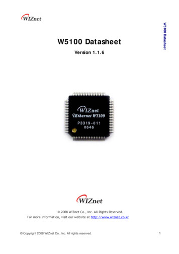
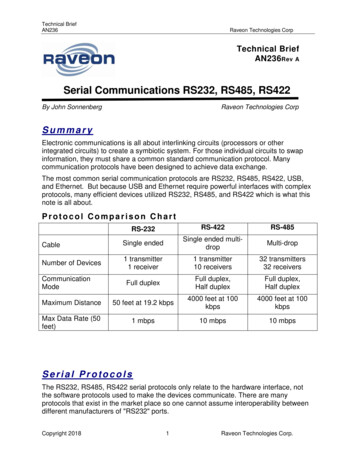
The higher a baud rate goes, the faster data is sent/received, but there are limits to how fast datacan be transferred. You usually won't see speeds exceeding 115200 - that's fast for mostmicrocontrollers. Get too high, and you'll begin to see errors on the receiving end, as clocks andsampling periods just can't keep up.Framing the dataEach block (usually a byte) of data transmitted is actually sent in apacket or frame of bits. Framesare created by appending synchronization and parity bits to our data.A serial frame. Some symbols in the frame have configurable bit sizes.Let's get into the details of each of these frame pieces.Data chunkThe real meat of every serial packet is the data it carries. We ambiguously call this block of data achunk, because its size isn't specifically stated. The amount of data in each packet can be set toanything from 5 to 9 bits. Certainly, the standard data size is your basic 8-bit byte, but other sizeshave their uses. A 7-bit data chunk can be more efficient than 8, especially if you're just transferring7-bit ASCII characters.After agreeing on a character-length, both serial devices also have to agree on theendianness oftheir data. Is data sent most-significant bit (msb) to least, or vice-versa? If it's not otherwise stated,you can usually assume that data is transferred least-significant bit (lsb) first.Synchronization bitsThe synchronization bits are two or three special bits transferred with each chunk of data. They arethe start bit and the stop bit(s). True to their name, these bits mark the beginning and end of apacket. There's always only one start bit, but the number of stop bits is configurable to either one ortwo (though it's commonly left at one).The start bit is always indicated by an idle data line going from 1 to 0, while the stop bit(s) willtransition back to the idle state by holding the line at 1.Parity bitsParity is a form of very simple, low-level error checking. It comes in two flavors: odd or even. Toproduce the parity bit, all 5-9 bits of the data byte are added up, and the evenness of the sumdecides whether the bit is set or not. For example, assuming parity is set to even and was beingPage 5 of 16
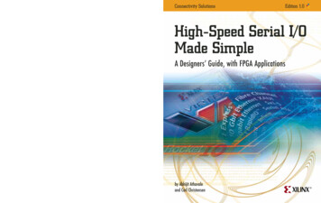
added to a data byte like 0b01011101, which has an odd number of 1's (5), the parity bit would be setto 1. Conversely, if the parity mode was set to odd, the parity bit would be0.Parity is optional, and not very widely used. It can be helpful for transmitting across noisy mediums,but it'll also slow down your data transfer a bit and requires both sender and receiver to implementerror-handling (usually, received data that fails must be re-sent).9600 8N1 (an example)9600 8N1 - 9600 baud, 8 data bits, no parity, and 1 stop bit - is one of the more commonly usedserial protocols. So, what would a packet or two of 9600 8N1 data look like? Let's have an example!A device transmitting the ASCII characters 'O' and 'K' would have to create two packets of data.The ASCII value of O (that's uppercase) is 79, which breaks down into an 8-bit binary value of01001111, while K's binary value is 01001011. All that's left is appending sync bits.It isn't specifically stated, but it’s assumed that data is transferred least-significant bit first. Noticehow each of the two bytes is sent as it reads from right-to-left.Since we're transferring at 9600 bps, the time spent holding each of those bits high or low is1/(9600 bps) or 104 µs per bit.For every byte of data transmitted, there are actually 10 bits being sent: a start bit, 8 data bits, anda stop bit. So, at 9600 bps, we're actually sending 9600 bits per second or 960 (9600/10) bytes persecond.Now that you know how to construct serial packets, we can move on to the hardware section. Therewe'll see how those 1's and 0's and the baud rate are implemented at a signal level!Wiring and HardwareA serial bus consists of just two wires - one for sending data and another for receiving. As such,serial devices should have two serial pins: the receiver, RX, and the transmitter, TX.Page 6 of 16
It's important to note that those RX and TX labels are with respect to the device itself. So the RXfrom one device should go to the TX of the other, and vice-versa. It's weird if you're used to hookingup VCC to VCC, GND to GND, MOSI to MOSI, etc., but it makes sense if you think about it. Thetransmitter should be talking to the receiver, not to another transmitter.A serial interface where both devices may send and receive data is eitherfull-duplex or halfduplex. Full-duplex means both devices can send and receive simultaneously. Half-duplexcommunication means serial devices must take turns sending and receiving.Some serial busses might get away with just a single connection between a sending and receivingdevice. For example, our Serial Enabled LCDs are all ears and don't really have any data to relayback to the controlling device. This is what's known as simplex serial communication. All you needis a single wire from the master device's TX to the listener's RX line.Hardware ImplementationWe've covered asynchronous serial from a conceptual side. We know which wires we need. Buthow is serial communication actually implemented at a signal level? In a variety of ways, actually.There are all sorts of standards for serial signaling. Let's look at a couple of the more popularhardware implementations of serial: logic-level (TTL) and RS-232.When microcontrollers and other low-level ICs communicate serially they usually do so at a TTL(transistor-transistor logic) level. TTL serial signals exist between a microcontroller's voltage supplyrange - usually 0V to 3.3V or 5V. A signal at the VCC level (3.3V, 5V, etc.) indicates either an idleline, a bit of value 1, or a stop bit. A 0V (GND) signal represents either a start bit or a data bit ofvalue 0.Page 7 of 16
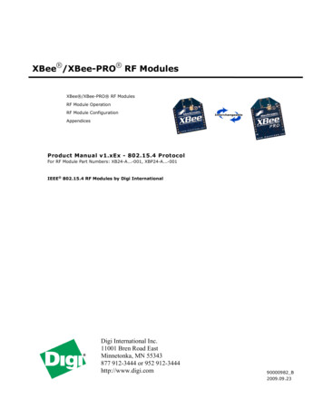
RS-232, which can be found on some of the more ancient computers and peripherals, is like TTLserial flipped on its head. RS-232 signals usually range between -13V and 13V, though the specallows for anything from /- 3V to /- 25V. On these signals a low voltage (-5V, -13V, etc.) indicateseither the idle line, a stop bit, or a data bit of value 1. A high RS-232 signal means either a start bit,or a 0-value data bit. That's kind of the opposite of TTL serial.Between the two serial signal standards, TTL is much easier to implement into embedded circuits.However the low voltage levels are more susceptible to losses across long transmission lines. RS232, or more complex standards like RS-485, are better suited to long range serial transmissions.When you're connecting two serial devices together, it's important to make sure their signalvoltages match up. You can't directly interface a TTL serial device with an RS-232 bus. You'll haveto shift those signals!Continuing on, we'll explore the tool microcontrollers use to convert their data on a parallel bus toand from a serial interface. UARTs!UARTsThe final piece to this serial puzzle is finding something to both create the serial packets andcontrol those physical hardware lines. Enter the UART.A universal asynchronous receiver/transmitter (UART) is a block of circuitry responsible forimplementing serial communication. Essentially, the UART acts as an intermediary between paralleland serial interfaces. On one end of the UART is a bus of eight-or-so data lines (plus some controlpins), on the other is the two serial wires - RX and TX.Page 8 of 16
Super-simplified UART interface. Parallel on one end, serial on the other.UARTs do exist as stand-alone ICs, but they're more commonly found inside microcontrollers. You'llhave to check your microcontroller's datasheet to see if it has any UARTs. Some have none, somehave one, some have many. For example, the Arduino Uno - based on the "old faithful"ATmega328 - has just a single UART, while the Arduino Mega - built on an ATmega2560 - has awhopping four UARTs.As the R and T in the acronym dictate, UARTs are responsible for both sending and receiving serialdata. On the transmit side, a UART must create the data packet - appending sync and parity bits and
from a basic Arduino Uno to a Mega, you know that the I/O lines on a microprocessor can be precious and few. So, we often opt for serial communication, sacrificing potential speed for pin real Page 2 of 16. estate. Asynchronous Serial Over the years, dozens of serial protocols have been crafted to meet particular needs of embedded systems. USB (universal serial bus), and Ethernet, are a couple .