Transcription
K-type Programmable ControllersOPERATION MANUALRevised July 1999
Notice:OMRON products are manufactured for use according to proper procedures by a qualified operatorand only for the purposes described in this manual.The following conventions are used to indicate and classify precautions in this manual. Always heedthe information provided with them. Failure to heed precautions can result in injury to people or damage to property.DANGERIndicates an imminently hazardous situation which, if not avoided, will result in death orserious injury.! WARNINGIndicates a potentially hazardous situation which, if not avoided, could result in death orserious injury.! CautionIndicates a potentially hazardous situation which, if not avoided, may result in minor ormoderate injury, or property damage.!OMRON Product ReferencesAll OMRON products are capitalized in this manual. The word “Unit” is also capitalized when it refersto an OMRON product, regardless of whether or not it appears in the proper name of the product.The abbreviation “Ch,” which appears in some displays and on some OMRON products, often means“word” and is abbreviated “Wd” in documentation in this sense.The abbreviation “PC” means Programmable Controller and is not used as an abbreviation for anything else.Visual AidsThe following headings appear in the left column of the manual to help you locate different types ofinformation.Note Indicates information of particular interest for efficient and convenient operationof the product.1, 2, 3.1. Indicates lists of one sort or another, such as procedures, checklists, etc. OMRON, 1992All rights reserved. No part of this publication may be reproduced, stored in a retrieval system, or transmitted, in anyform, or by any means, mechanical, electronic, photocopying, recording, or otherwise, without the prior written permission of OMRON.No patent liability is assumed with respect to the use of the information contained herein. Moreover, because OMRON isconstantly striving to improve its high-quality products, the information contained in this manual is subject to changewithout notice. Every precaution has been taken in the preparation of this manual. Nevertheless, OMRON assumes noresponsibility for errors or omissions. Neither is any liability assumed for damages resulting from the use of the information contained in this publication.v
TABLE OF CONTENTSPRECAUTIONS . . . . . . . . . . . . . . . . . . . . . . . . . . . . . . . . .1 Intended Audience . . . . . . . . . . . . . . . . . . . . . . . . . . . . . . . . . . . . . . . . . . . . . . . . . . . . . . . . . . .2 General Precautions . . . . . . . . . . . . . . . . . . . . . . . . . . . . . . . . . . . . . . . . . . . . . . . . . . . . . . . . . .3 Safety Precautions . . . . . . . . . . . . . . . . . . . . . . . . . . . . . . . . . . . . . . . . . . . . . . . . . . . . . . . . . . .4 Operating Environment Precautions . . . . . . . . . . . . . . . . . . . . . . . . . . . . . . . . . . . . . . . . . . . . .5 Application Precautions . . . . . . . . . . . . . . . . . . . . . . . . . . . . . . . . . . . . . . . . . . . . . . . . . . . . . .SECTION 1Background . . . . . . . . . . . . . . . . . . . . . . . . . . . . . . . . . . . .1-11-21-31-41-51-61-7Introduction . . . . . . . . . . . . . . . . . . . . . . . . . . . . . . . . . . . . . . . . . . . . . . . . . . . . . . . . . . . .Relay Circuits: The Roots of PC Logic . . . . . . . . . . . . . . . . . . . . . . . . . . . . . . . . . . . . . . .PC Terminology . . . . . . . . . . . . . . . . . . . . . . . . . . . . . . . . . . . . . . . . . . . . . . . . . . . . . . . . .OMRON Product Terminology . . . . . . . . . . . . . . . . . . . . . . . . . . . . . . . . . . . . . . . . . . . . .Overview of PC Operation . . . . . . . . . . . . . . . . . . . . . . . . . . . . . . . . . . . . . . . . . . . . . . . . .Peripheral Devices . . . . . . . . . . . . . . . . . . . . . . . . . . . . . . . . . . . . . . . . . . . . . . . . . . . . . . .Available Manuals . . . . . . . . . . . . . . . . . . . . . . . . . . . . . . . . . . . . . . . . . . . . . . . . . . . . . . .SECTION 2Hardware Considerations . . . . . . . . . . . . . . . . . . . . . . . . .2-12-22-3Introduction . . . . . . . . . . . . . . . . . . . . . . . . . . . . . . . . . . . . . . . . . . . . . . . . . . . . . . . . . . . .Indicators . . . . . . . . . . . . . . . . . . . . . . . . . . . . . . . . . . . . . . . . . . . . . . . . . . . . . . . . . . . . . .PC Configuration . . . . . . . . . . . . . . . . . . . . . . . . . . . . . . . . . . . . . . . . . . . . . . . . . . . . . . . .SECTION 3Memory Areas . . . . . . . . . . . . . . . . . . . . . . . . . . . . . . . . . .3-13-23-33-43-53-63-73-8Introduction . . . . . . . . . . . . . . . . . . . . . . . . . . . . . . . . . . . . . . . . . . . . . . . . . . . . . . . . . . . .Data Area Structure . . . . . . . . . . . . . . . . . . . . . . . . . . . . . . . . . . . . . . . . . . . . . . . . . . . . . .Internal Relay (IR) Area . . . . . . . . . . . . . . . . . . . . . . . . . . . . . . . . . . . . . . . . . . . . . . . . . .Special Relay (SR) Area . . . . . . . . . . . . . . . . . . . . . . . . . . . . . . . . . . . . . . . . . . . . . . . . . .Data Memory (DM) Area . . . . . . . . . . . . . . . . . . . . . . . . . . . . . . . . . . . . . . . . . . . . . . . . . .Holding Relay (HR) Area . . . . . . . . . . . . . . . . . . . . . . . . . . . . . . . . . . . . . . . . . . . . . . . . .Timer/Counter (TC) Area . . . . . . . . . . . . . . . . . . . . . . . . . . . . . . . . . . . . . . . . . . . . . . . . .Temporary Relay (TR) Area . . . . . . . . . . . . . . . . . . . . . . . . . . . . . . . . . . . . . . . . . . . . . . .SECTION 4Writing and Inputting the Program . . . . . . . . . . . . . . . . .4-14-24-34-44-54-64-74-84-94-10Introduction . . . . . . . . . . . . . . . . . . . . . . . . . . . . . . . . . . . . . . . . . . . . . . . . . . . . . . . . . . . .Instruction Terminology . . . . . . . . . . . . . . . . . . . . . . . . . . . . . . . . . . . . . . . . . . . . . . . . . . .The Ladder Diagram . . . . . . . . . . . . . . . . . . . . . . . . . . . . . . . . . . . . . . . . . . . . . . . . . . . . .The Programming Console . . . . . . . . . . . . . . . . . . . . . . . . . . . . . . . . . . . . . . . . . . . . . . . .Preparation for Operation . . . . . . . . . . . . . . . . . . . . . . . . . . . . . . . . . . . . . . . . . . . . . . . . . .Inputting, Modifying, and Checking the Program . . . . . . . . . . . . . . . . . . . . . . . . . . . . . . .Controlling Bit Status . . . . . . . . . . . . . . . . . . . . . . . . . . . . . . . . . . . . . . . . . . . . . . . . . . . . .Work Bits (Internal Relays) . . . . . . . . . . . . . . . . . . . . . . . . . . . . . . . . . . . . . . . . . . . . . . . .Programming Precautions . . . . . . . . . . . . . . . . . . . . . . . . . . . . . . . . . . . . . . . . . . . . . . . . .Program Execution . . . . . . . . . . . . . . . . . . . . . . . . . . . . . . . . . . . . . . . . . . . . . . . . . . . . . . .vii
TABLE OF CONTENTSSECTION 5Instruction Set . . . . . . . . . . . . . . . . . . . . . . . . . . . . . . . . . 155-165-175-185-19Introduction . . . . . . . . . . . . . . . . . . . . . . . . . . . . . . . . . . . . . . . . . . . . . . . . . . . . . . . . . . . .Notation . . . . . . . . . . . . . . . . . . . . . . . . . . . . . . . . . . . . . . . . . . . . . . . . . . . . . . . . . . . . . . .Instruction Format . . . . . . . . . . . . . . . . . . . . . . . . . . . . . . . . . . . . . . . . . . . . . . . . . . . . . . .Data Areas, Definer Values, and Flags . . . . . . . . . . . . . . . . . . . . . . . . . . . . . . . . . . . . . . .Ladder Diagram Instructions . . . . . . . . . . . . . . . . . . . . . . . . . . . . . . . . . . . . . . . . . . . . . . .Bit Control Instructions . . . . . . . . . . . . . . . . . . . . . . . . . . . . . . . . . . . . . . . . . . . . . . . . . . .INTERLOCK and INTERLOCK CLEAR – IL(02) and ILC(03) . . . . . . . . . . . . . . . . . . .JUMP and JUMP END – JMP(04) and JME(05) . . . . . . . . . . . . . . . . . . . . . . . . . . . . . . . .END – END(01) . . . . . . . . . . . . . . . . . . . . . . . . . . . . . . . . . . . . . . . . . . . . . . . . . . . . . . . . .NO OPERATION – NOP(00) . . . . . . . . . . . . . . . . . . . . . . . . . . . . . . . . . . . . . . . . . . . . . . .Timer and Counter Instructions . . . . . . . . . . . . . . . . . . . . . . . . . . . . . . . . . . . . . . . . . . . . .Data Shifting . . . . . . . . . . . . . . . . . . . . . . . . . . . . . . . . . . . . . . . . . . . . . . . . . . . . . . . . . . .Data Movement . . . . . . . . . . . . . . . . . . . . . . . . . . . . . . . . . . . . . . . . . . . . . . . . . . . . . . . . .DATA COMPARE – CMP(20) . . . . . . . . . . . . . . . . . . . . . . . . . . . . . . . . . . . . . . . . . . . . . .Data Conversion . . . . . . . . . . . . . . . . . . . . . . . . . . . . . . . . . . . . . . . . . . . . . . . . . . . . . . . . .BCD Calculations . . . . . . . . . . . . . . . . . . . . . . . . . . . . . . . . . . . . . . . . . . . . . . . . . . . . . . . .Subroutines . . . . . . . . . . . . . . . . . . . . . . . . . . . . . . . . . . . . . . . . . . . . . . . . . . . . . . . . . . . . .Step Instructions . . . . . . . . . . . . . . . . . . . . . . . . . . . . . . . . . . . . . . . . . . . . . . . . . . . . . . . . .Special Instructions . . . . . . . . . . . . . . . . . . . . . . . . . . . . . . . . . . . . . . . . . . . . . . . . . . . . . .SECTION 6Program Execution Timing . . . . . . . . . . . . . . . . . . . . . . . .6-16-26-36-46-5Introduction . . . . . . . . . . . . . . . . . . . . . . . . . . . . . . . . . . . . . . . . . . . . . . . . . . . . . . . . . . . .Cycle Time . . . . . . . . . . . . . . . . . . . . . . . . . . . . . . . . . . . . . . . . . . . . . . . . . . . . . . . . . . . . .Calculating Cycle Time . . . . . . . . . . . . . . . . . . . . . . . . . . . . . . . . . . . . . . . . . . . . . . . . . . .Instruction Execution Times . . . . . . . . . . . . . . . . . . . . . . . . . . . . . . . . . . . . . . . . . . . . . . .I/O Response Time . . . . . . . . . . . . . . . . . . . . . . . . . . . . . . . . . . . . . . . . . . . . . . . . . . . . . . .SECTION 7Program Debugging and Execution . . . . . . . . . . . . . . . . .7-17-27-37-4Introduction . . . . . . . . . . . . . . . . . . . . . . . . . . . . . . . . . . . . . . . . . . . . . . . . . . . . . . . . . . . .Debugging . . . . . . . . . . . . . . . . . . . . . . . . . . . . . . . . . . . . . . . . . . . . . . . . . . . . . . . . . . . . .Monitoring Operation and Modifying Data . . . . . . . . . . . . . . . . . . . . . . . . . . . . . . . . . . . .Program Backup and Restore Operations . . . . . . . . . . . . . . . . . . . . . . . . . . . . . . . . . . . . .SECTION 8Troubleshooting . . . . . . . . . . . . . . . . . . . . . . . . . . . . . . . . .8-18-28-38-4Introduction . . . . . . . . . . . . . . . . . . . . . . . . . . . . . . . . . . . . . . . . . . . . . . . . . . . . . . . . . . . .Reading and Clearing Errors and Messages . . . . . . . . . . . . . . . . . . . . . . . . . . . . . . . . . . .Error Messages . . . . . . . . . . . . . . . . . . . . . . . . . . . . . . . . . . . . . . . . . . . . . . . . . . . . . . . . . .Error Flags . . . . . . . . . . . . . . . . . . . . . . . . . . . . . . . . . . . . . . . . . . . . . . . . . . . . . . . . . . . . .AppendicesABCDEFGStandard Models . . . . . . . . . . . . . . . . . . . . . . . . . . . . . . . . . . . . . . . . . . . . . . . . . . . . . . . . . . .Programming Instructions and Execution Times . . . . . . . . . . . . . . . . . . . . . . . . . . . . . . . . . .Programming Console Operations . . . . . . . . . . . . . . . . . . . . . . . . . . . . . . . . . . . . . . . . . . . . . .Error and Arithmetic Flag Operation . . . . . . . . . . . . . . . . . . . . . . . . . . . . . . . . . . . . . . . . . . . .Binary–Hexadecimal–Decimal Table . . . . . . . . . . . . . . . . . . . . . . . . . . . . . . . . . . . . . . . . . . .Word Assignment Recording Sheets . . . . . . . . . . . . . . . . . . . . . . . . . . . . . . . . . . . . . . . . . . . .Program Coding Sheet . . . . . . . . . . . . . . . . . . . . . . . . . . . . . . . . . . . . . . . . . . . . . . . . . . . . . . .Glossary . . . . . . . . . . . . . . . . . . . . . . . . . . . . . . . . . . . . . . .Index . . . . . . . . . . . . . . . . . . . . . . . . . . . . . . . . . . . . . . . . . .Revision History . . . . . . . . . . . . . . . . . . . . . . . . . . . . . . . . .viii
About this Manual:The OMRON K-type Programmable Controllers offer an effective way to automate processing, manufacturing, assembly, packaging, and many other processes to save time and money. Distributed control systems can also be designed to allow centralized monitoring and supervision of several separatecontrolled systems. Monitoring and supervising can be done through a host computer, connecting thecontrolled system to a data bank. It is thus possible to have adjustments in system operation madeautomatically to compensate for requirement changes.The K-type Units can utilize a number of additional Units including dedicated Special I/O Units thatcan be used for specific tasks and Link Units that can be used to build more highly integrated systems.The K-types are equipped with large programming instruction sets, data areas, and other features tocontrol processing directly. Programming utilizes ladder-diagram programming methods, which aredescribed in detail for those unfamiliar with them.This manual describes the characteristics and abilities of the K-types programming operations, instructions, and other aspects of operation and preparation that demand attention. Before attemptingto operate the PC, thoroughly familiarize yourself with the information contained herein. Hardwareinformation is provided in detail in the Installation Guide. A table of other manuals that can be used incombination with this manual is provided at the end of Section 1 Introduction.Section 1 Introduction explains the background and some of the basic terms used in ladder-diagram programming. It also provides an overview of the process of programming and operating a PCand explains basic terminology used with OMRON PCs. Descriptions of peripheral devices used withthe K-types and a table of other manuals available to use with this manual for special PC applicationsare also provided.Section 2 Hardware Considerations explains basic aspects of the overall PC configuration and describes the indicators that are referred to in other sections of this manual.Section 3 Memory Areas takes a look at the way memory is divided and allocated and explains theinformation provided there to aid in programming. It also explains how I/O is managed in memory andhow bits in memory correspond to specific I/O points.Section 4 Programming explains the basics of writing and inputting the ladder-diagram program,looking at the elements that make up the ‘ladder’ part of a ladder-diagram program and explaininghow execution of this program is controlled and the methods required to input it input the PC. Section 5 Instruction Set then goes on to describe individually all of the instructions used in programming, while Section 6 Program Execution Timing explains the scanning process used to executethe program and tells how to coordinate inputs and outputs so that they occur at the proper times.Section 7 Debugging and Execution provides the Programming Console procedures used to debugthe program and to monitor and control system operation.Finally, Section 8 Troubleshooting provides information on system error indications and othermeans of reducing system down time. Information in this section is also necessary when debugging aprogram.The Appendices provide tables of standard OMRON products available for the K-types, referencetables of instructions and Programming Console operations, and other information helpful in PC operation.! WARNING Failure to read and understand the information provided in this manual may result inpersonal injury or death, damage to the product, or product failure. Please read eachsection in its entirety and be sure you understand the information provided in the sectionand related sections before attempting any of the procedures or operations given.ix
PRECAUTIONSThis section provides general precautions for using the K-type Programmable Controllers (PCs) and related devices.The information contained in this section is important for the safe and reliable application of Programmable Controllers. You must read this section and understand the information contained before attempting to set up or operate a PCsystem.1 Intended Audience . . . . . . . . . . . . . . . . . . . . . . . . . . . . . . . . . . . . . . . . . . . . . . . . . . . . . . . . . . . .2 General Precautions . . . . . . . . . . . . . . . . . . . . . . . . . . . . . . . . . . . . . . . . . . . . . . . . . . . . . . . . . . .3 Safety Precautions . . . . . . . . . . . . . . . . . . . . . . . . . . . . . . . . . . . . . . . . . . . . . . . . . . . . . . . . . . . .4 Operating Environment Precautions . . . . . . . . . . . . . . . . . . . . . . . . . . . . . . . . . . . . . . . . . . . . . .5 Application Precautions . . . . . . . . . . . . . . . . . . . . . . . . . . . . . . . . . . . . . . . . . . . . . . . . . . . . . . . .xi
Operating Environment Precautions14Intended AudienceThis manual is intended for the following personnel, who must also have knowledge of electrical systems (an electrical engineer or the equivalent). Personnel in charge of installing FA systems. Personnel in charge of designing FA systems. Personnel in charge of managing FA systems and facilities.2General PrecautionsThe user must operate the product according to the performance specificationsdescribed in the operation manuals.Before using the product under conditions which are not described in the manualor applying the product to nuclear control systems, railroad systems, aviationsystems, vehicles, combustion systems, medical equipment, amusement machines, safety equipment, and other systems, machines, and equipment thatmay have a serious influence on lives and property if used improperly, consultyour OMRON representative.Make sure that the ratings and performance characteristics of the product aresufficient for the systems, machines, and equipment, and be sure to provide thesystems, machines, and equipment with double safety mechanisms.This manual provides information for programming and operating the Unit. Besure to read this manual before attempting to use the Unit and keep this manualclose at hand for reference during operation.! WARNING It is extremely important that a PC and all PC Units be used for the specifiedpurpose and under the specified conditions, especially in applications that candirectly or indirectly affect human life. You must consult with your OMRONrepresentative before applying a PC System to the above-mentionedapplications.3Safety Precautions! WARNING Do not attempt to take any Unit apart while the power is being supplied. Doing somay result in electric shock.! WARNING Do not touch any of the terminals or terminal blocks while the power is beingsupplied. Doing so may result in electric shock.! WARNING Do not attempt to disassemble, repair, or modify any Units. Any attempt to do somay result in malfunction, fire, or electric shock.4Operating Environment Precautions! CautionDo not operate the control system in the following locations: Locations subject to direct sunlight. Locations subject to temperatures or humidity outside the range specified inthe specifications. Locations subject to condensation as the result of severe changes in temperature.xii
5Application Precautions Locations subject to corrosive or flammable gases. Locations subject to dust (especially iron dust) or salts. Locations subject to exposure to water, oil, or chemicals. Locations subject to shock or vibration.! CautionTake appropriate and sufficient countermeasures when installing systems in thefollowing locations: Locations subject to static electricity or other forms of noise. Locations subject to strong electromagnetic fields. Locations subject to possible exposure to radioactivity. Locations close to power supplies.! Caution5The operating environment of the PC System can have a large effect on the longevity and reliability of the system. Improper operating environments can lead tomalfunction, failure, and other unforeseeable problems with the PC System. Besure that the operating environment is within the specified conditions at installation and remains within the specified conditions during the life of the system.Application PrecautionsObserve the following precautions when using the PC System.! WARNING Always heed these precautions. Failure to abide by the following precautionscould lead to serious or possibly fatal injury. Always ground the system to 100 Ω or less when installing the Units. Not connecting to a ground of 100 Ω or less may result in electric shock. Always turn OFF the power supply to the PC before attempting any of the following. Not turning OFF the power supply may result in malfunction or electricshock. Mounting or dismounting I/O Units, CPU Units, Memory Cassettes, or anyother Units. Assembling the Units. Setting DIP switches or rotary switches. Connecting cables or wiring the system. Connecting or disconnecting the connectors.! CautionFailure to abide by the following precautions could lead to faulty operation of thePC or the system, or could damage the PC or PC Units. Always heed these precautions. Fail-safe measures must be taken by the customer to ensure safety in theevent of incorrect, missing, or abnormal signals caused by broken signal lines,momentary power interruptions, or other causes. Interlock circuits, limit circuits, and similar safety measures in external circuits(i.e., not in the Programmable Controller) must be provided by the customer. Always use the power supply voltages specified in the operation manuals. Anincorrect voltage may result in malfunction or burning. Take appropriate measures to ensure that the specified power with the ratedvoltage and frequency is supplied. Be particularly careful in places where thepower supply is unstable. An incorrect power supply may result in malfunction. Install external breakers and take other safety measures against short-circuiting in external wiring. Insufficient safety measures against short-circuiting mayresult in burning.xiii
Application Precautions5 Do not apply voltages to the Input Units in excess of the rated input voltage.Excess voltages may result in burning. Do not apply voltages or connect loads to the Output Units in excess of themaximum switching capacity. Excess voltages or loads may result in burning. Disconnect the functional ground terminal when performing withstand voltagetests. Not disconnecting the functional ground terminal may result in burning. Be sure that all the mounting screws, terminal screws, and cable connectorscrews are tightened to the torque specified in the relevant manuals. Incorrecttightening torque may result in malfunction. Leave the label attached to the Unit when wiring. Removing the label may result in malfunction if foreign matter enters the Unit. Remove the label after the completion of wiring to ensure proper heat dissipation. Leaving the label attached may result in malfunction. Use crimp terminals for wiring. Do not connect bare stranded wires directly toterminals. Connection of bare stranded wires may result in burning. Wire all connections correctly. Double-check all wiring and switch settings before turning ON the power supply. Incorrect wiring may result in burning. Be sure that the terminal blocks, Memory Units, expansion cables, and otheritems with locking devices are properly locked into place. Improper lockingmay result in malfunction. Check the user program for proper execution before actually running it on theUnit. Not checking the program may result in an unexpected operation. Confirm that no adverse effect will occur in the system before attempting any ofthe following. Not doing so may result in an unexpected operation. Changing the operating mode of the PC. Force-setting/force-resetting any bit in memory. Changing the present value of any word or any set value in memory. Resume operation only after transferring to the new CPU Unit the contents ofthe DM Area, HR Area, and other data required for resuming operation. Notdoing so may result in an unexpected operation. Do not pull on the cables or bend the cables beyond their natural limit. Doingeither of these may break the cables. Do not place objects on top of the cables or other wiring lines. Doing so maybreak the cables. When replacing parts, be sure to confirm that the rating of a new part is correct.Not doing so may result in malfunction or burning. Before touching a Unit, be sure to first touch a grounded metallic object in orderto discharge any static built-up. Not doing so may result in malfunction or damage. Install the Units properly as specified in the operation manuals. Improperinstallation of the Units may result in malfunction.xiv
SECTION 1Background1-11-21-31-41-51-61-7Introduction . . . . . . . . . . . . . . . . . . . . . . . . . . . . . . . . . . . . . . . . . . . . . . . . . . . . . . . . . . . . .Relay Circuits: The Roots of PC Logic . . . . . . . . . . . . . . . . . . . . . . . . . . . . . . . . . . . . . . . .PC Terminology . . . . . . . . . . . . . . . . . . . . . . . . . . . . . . . . . . . . . . . . . . . . . . . . . . . . . . . . . .OMRON Product Terminology . . . . . . . . . . . . . . . . . . . . . . . . . . . . . . . . . . . . . . . . . . . . . .Overview of PC Operation . . . . . . . . . . . . . . . . . . . . . . . . . . . . . . . . . . . . . . . . . . . . . . . . . .Peripheral Devices . . . . . . . . . . . . . . . . . . . . . . . . . . . . . . . . . . . . . . . . . . . . . . . . . . . . . . . .Available Manuals . . . . . . . . . . . . . . . . . . . . . . . . . . . . . . . . . . . . . . . . . . . . . . . . . . . . . . . .1
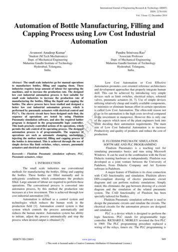
Section 1-2Relay Circuits: The Roots of PC Logic1-1IntroductionA Programmable Controller (PC) is basically a central processing unit (CPU)containing a program and connected to input and output (I/O) devices (I/ODevices). The program controls the PC so that when an input signal from aninput device turns ON, the appropriate response is made. The response normally involves turning ON an output signal to some sort of output device. Theinput devices could be photoelectric sensors, pushbuttons on control panels,limit switches, or any other device that can produce a signal that can be inputinto the PC. The output devices could be solenoids, switches activating indicator lamps, relays turning on motors, or any other devices that can be activated by signals output from the PC.For example, a sensor detecting a product passing by turns ON an input tothe PC. The PC responds by turning ON an output that activates a pusherthat pushes the product onto another conveyor for further processing. Another sensor, positioned higher than the first, turns ON a different input toindicate that the product is too tall. The PC responds by turning on anotherpusher positioned before the pusher mentioned above to push the too-tallproduct into a rejection box.Although this example involves only two inputs and two outputs, it is typical ofthe type of control operation that PCs can achieve. Actually even this example is much more complex than it may at first appear because of the timingthat would be required, i.e., “How does the PC know when to activate eachpusher?” Much more complicated operations, however, are also possible.The problem is how to get the desired control signals from available inputs atappropriate times.Desired control sequences are input to the K-type PCs using a form of PClogic called ladder-diagram programming. This manual is written to explainladder-diagram programming and to prepare the reader to program and operate the K-type PCs.1-2Relay Circuits: The Roots of PC LogicPCs historically originate in relay-based control systems. And although theintegrated circuits and internal logic of the PC have taken the place of thediscrete relays, timers, counters, and other such devices, actual PC operation proceeds as if those discrete devices were still in place. PC control, however, also provides computer capabilities and consistency to achieve a greatdeal more flexibility and reliability than is possible with relays.The symbols and other control concepts used to describe PC operation alsocome from relay-based control and form the basis of the ladder-diagram programming method. Most of the terms used to describe these symbols andconcepts, however, originated as computer terminology.Relay vs. PC TerminologyThe terminology used throughout this manual is somewhat different from relay terminology, but the concepts are the same. The following table showsthe relationship between relay terms and the PC terms used for OMRONPCs.Relay term2PC equivalentcontactinput or conditioncoiloutput or work bitNO relaynormally open conditionNC relaynormally closed condition
OMRON Product TerminologySection 1-4Actually there is not a total equivalence between these terms, because theterm condition is used only to describe ladder diagram programs in generaland is specifically equivalent to one of certain basic instructions. The termsinput and output are not used in programming per se, except in reference toI/O bits that are assigned to input and output signals coming into and leavingthe PC. Normally open conditions and normally closed conditions are explained in 4-3 The Ladder Diagram.1-3PC TerminologyAlthough also provided in the Glossary at the back of this manual, the following terms are crucial to understand
Section 2 Hardware Considerations explains basic aspects of the overall PC configuration and de-scribes the indicators that are referred to in other sections of this manual. Section 3 Memory Areas takes a look at the way memory is divided and allocated and explains the information provided there to aid in programming.