Transcription
International Journal of Electrical & Computer Sciences IJECS-IJENS Vol: 11 No: 0669PLC Based Intelligent Traffic Control SystemMuhammad Arshad KhattakDepartment of Computer Science and Information TechnologySarhad University of Science and Information Technology (SUIT)Peshawar 25000 Pakistanarshad.csit@suit.edu.pkABSTRACTThe main object of this study was to design and implementintelligent traffic control system. The system developed is able tosense the presence or absence of vehicles within certain range bysetting the appropriate duration for the traffic signals to reactaccordingly. By employing mathematical functions to calculate theappropriate timing for the green signal to illuminate, the system canhelp to solve the problem of traffic congestion. Hardware simulationtests were successfully performed on the algorithm implemented intoa PLC (programmable logic controller).The new timing scheme that was implemented promises animprovement in the current traffic light system and this system isfeasible, affordable and ready to be implemented especially duringpeak hours, off hours and pedestrians.who know about the operation of traffic signals, the less frustratedthey are going to be while waiting for the lights to change. The mainaim in designing and developing of the Intelligent Traffic SignalSimulator is to reduce the waiting time of each lane of the cars andalso to maximize the total number of cars that can cross anintersection given the mathematical function to calculate the waitingtime.The Intelligent Traffic signal Control System consists of threeimportant parts. The first part is the PLC controller and second part ishardware. These usually comprise of red, yellow, and green lights.The third part is the sensor. The sensors check the presence ofvehicles.2.The PLC checks the status of the sensors. The systemresolution is depend on the output provided by the sensors , ThenPLC checks the priorities and then provide output signal to the trafficlights poles for ON or OFF the Red, yellow or Green lights and ONtime is depend on the specific priorities. The roads are opened in thatmanner that east road, west road, north road and then south road isopen.OVERVIEW OF PLC BASED ITCSThe main theme of this report is to build and verify the designs andunderstand the concept. The main objective is to build a hardwaredevice that has:1.The ability to collect the information of the busytracks by sensors and providing the output to PLC.2.The ability to take decision against the informationand change the time according to the priorities.2.1 Traffic Control System1.INTRODUCTIONTraffic load is highly dependent on parameters such as time, day,season, weather and unpredictable situations such as accidents, specialevents or construction activities. If these parameters are not taken intoaccount, the traffic control system will create bottlenecks and delays. Atraffic control system that solves these problems by continuouslysensing and monitoring traffic conditions and adjusting the timing oftraffic lights according to the actual traffic load is called an intelligenttraffic control system.Traffic control systems may also be classified as saturated orunsaturated, depending on whether they were designed for asaturated or unsaturated network. In an unsaturated network, it isdesired to minimize the mean delay of drivers, while in a saturatednetwork it is desired to serve as many drivers as possible, or in otherwords, to maximize traffic capacity of the intersection. The problemof capacity maximization is the same as the queue minimizationproblemThe older system uses weight as a trigger mechanism. Current trafficsystems react to motion to trigger the light changes. Once theinfrared object detector picks up the presence of a car, a switchcauses the lights to change.An adaptive traffic control system must have the ability to diagnosesaturation conditions in the network and change the objective functionas desired. In older fixed-time systems, there were multiple timingplans, but now a modern traffic control system can have multiplecontrol strategies.We need to understand the function of traffic signals so that we canimprove driving habits by controlling the speed in order to reduce thenumber of associated traffic accidents. The more number of drivers Traffic signals control vehicle movementsTraffic Control Systems are interconnected withelectronics system that controls traffic signals.Traffic Control Systems depend on logic whichcan be divided into these categories:i. The signal phases and cycle lengthare depend on the traffic flow on thedesired trackii. The system responds to interrupts ortiming base system and open thedesired signal according to thepriority requirement2.2 AdvantagesTraffic signals help control the flow of vehicles,pedestrians and bicycles by giving “right-of-way” to thevarious movements in an orderly manner. Signals that areproperly located, designed and maintained can: Provide for orderly movement of traffic. Increase capacity of the intersection. Reduce frequency and severity of certain types ofcrashes, especially right-angle collisions. Provide for continuous movement of traffic at adefinite speed along a given route. Interrupt heavy traffic at intervals to permit othervehicles or pedestrians to cross. Effectively perform traffic management Overall, traffic signals help us get where we’regoing safely and in a timely manner.110606-9494 IJECS-IJENS December 2011 IJENSIJENS
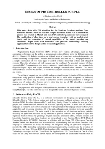
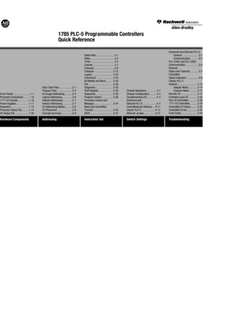
International Journal of Electrical & Computer Sciences IJECS-IJENS Vol: 11 No: 062.3 DisadvantagesTraffic signals are sometimes considered problems atintersections. In fact, traffic signals that are poorly locatedcan adversely affect the safety and efficiency of vehicle,bicycle and pedestrian traffic. Improper or unjustifiedsignals can result in one or more of the following: 70induction loop in Intelligent Traffic Control System is used toprovide an interrupt signal to controller unit. We use Photo electricsensors rather then induction loops. In our design, photo electricsensors provide an interrupt signal to controller unit. In case whenvehicle reaches in front of sensors, then it provides an interrupt.2.9 flow diagram of trafficNORTHSignificant increase in the frequency of some typesof collisionsIncreased congestion, air pollution, and fuelconsumption.Excessive delay.Excessive disobedience of the signal indications.Increased use of less adequate streets as motoristsattempt to avoid the traffic signals.Frustration especially in hot weather.2.4 What is Intelligent Traffic Control System (ITCS)?An Intelligent Traffic Control System senses the presenceor absence of vehicles and reacts according to the sensorsoutput. In this system PLC takes a data from sensors andchecks the priorities. After that PLC provides signal totraffic signals.The intelligent traffic control system works in fourdifferent modes are Normal flow, peak time, off time andmanual operation. Peak time and off time modes aredepended on the sensors outputs then change the status.Our intelligent traffic control system totally depend on thesensors output and take decisions.2.5 Study overviewSOUTH2.10 System block diagramThis study has two main parts. First is study of PLC and the secondpart is its application intelligent traffic control system. The intelligenttraffic control system has further divided into two main parts,Programming and hardware. Ladder logic Programming technique isused. PLC T100MD2424 is used for attaching with proto typehardware. In hardware photoelectric sensors is used for sensing thepresence the vehicles on the square in proto type.2.6 What is PLC?A PLC (Programmable Logic Controller) is a device that wasinvented to replace the necessary sequential relay circuits formachine control. The PLC works by looking at its inputs anddepending upon their state, turning on/off its outputs. The user entersa program, usually via software, that gives the desired results32.7 Practical System DesignPractically Inductive Loops are used as sensors to detect the presenceof vehicles on intersections. Its basic function is to provide interruptsto controller unit. It has two parts, first is coil and second is thedetector unit. Coil is a main part of a sensor and consists of one ormore loops of wire embedded in the pavement.This inductive coil is connected with the detector unit, which is anelectronic circuit. When vehicles passes over or rests on the inductiveloop then due to induction on vehicle more current flow throughinductive loop and this change of current also changes frequency.Detector unit can detect these changes. Finally, detector unit sends aninterrupt signal to controller unit.2.8SIMULATION3.1 ToolPrototype HardwareIn prototype design Photo electric sensors are used, for prototype it isnot possible to design an induction loop. As the basic function ofTRILOGI software has built in simulator engine. It is used withoutattaching the PLC hardware. This is the main advantage of theTRILOGI software. This type of feather is not used in other software3.2 Advantages of TRILOGI softwareThe main advantage of the TRILOGI software has it’s built insimulator engine that provide us the facility to simulate the programany time without attaching the plc module. We check our allpriorities, inputs, interrupts, timers, relays, counters and its outputstatus in live condition. This is the big advantage of TRILOGIsoftware.3.3 PLC simulator Trilogy has built in simulator engine which is in effect a“soft PLC” Great ease of program testing and debugging110606-9494 IJECS-IJENS December 2011 IJENSIJENS
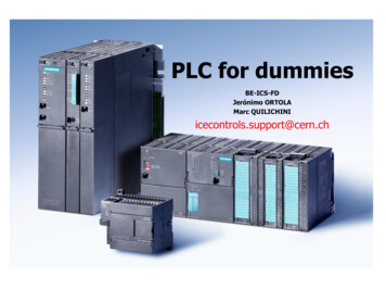
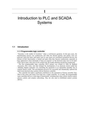
International Journal of Electrical & Computer Sciences IJECS-IJENS Vol: 11 No: 06 Test run of program off-line directly on the same pc thatruns TRILOGYProgram can be distributed amount students to run that athome and test their logics without the need of PLCRemotely program, monitor, control and troubleshoot yoursuper PLC controlled equipment via the internet at anytimeRemote software updatePLC can e-mail specific reports at required timePLC can send SMS with just a single line of code71Digital I/O Ports: Detachable screw terminals are provided forquick connection to all digital inputs, outputs and power supplywires. Each block of screw terminals can easily be detached fromthe controller body, enabling easy replacement of the controllerboard when necessary. Since the terminal block for digital I/Os areinserted vertically to the board surface, you need to remove theterminal block before you can start wiring. Use a small flat-headscrewdriver and insert underneath the terminal block, apply evenpressure to raise the terminal block until it becomes loosened fromthe connecting-pin strip, as shown below:A l t h ou g h w i r e s of up t o 2 4 A W G ma y b e c o n n ec t edd i r ec t l y t o t he s c r ew t e r m i na l , i n s u l a t ed c r i mpf e r r ul e s s ho u l d b e u s e d t o p r o vi d e a g o o d e n dt e r mi n a t i o n t o m u l t i t hr ea de d w i r e s . U s e of f e r r ul e sr e d uc es t he p os s i b i l i t y of s t r a y w i r e - s t r a n ds s h or tc i r c u i t i n g a dj a c e nt t er mi n a l s a nd t h e i r u s e i s t her e f or eh i g hl y r e c o m m e n de d.4HARDWARE IMPLEMENTATION4.1 Hardware Components1. PLC T100MD module2. Interface card3. Photoelectric Sensors4. Signal poles5. Communication Ports6. Toggle Switches7. Proto type hardware4.2 PLC T100MD moduleT100MD2424 is a new member of the highly popular T100MDPLC family. The basic unit comprises 8 analog I/Os, 24 digital Inputsand 24 digital outputs. Two of the digital outputs (7 & 8) which canbe also defined as PWM outputs can each deliver up to 10A peakand 2A continuous, 24VDC (active high) current to the load. The 8analog I/Os are configurable as 8 AI, no AO or 6 AI and 2 AO. Allanalog inputs are 10-bit resolution and all analog outputs are 8-bitresolution.T100MD2424 is expandable up to a total of 96 digital inputs and 96digital outputs with an optional expansion module. It has an RS232and an RS485 port. Both of them are conversant in MODBUSprotocol. The built-in LCD port allows simple interface to industrystandard LCD modules from 8 characters to 80 characters.The compactly designed T100MD2424 PLC can be easily installedin many kinds of plastic or metal enclosures. You need to use 4 or 5PCB standoffs (or some screws and nuts) to support the controllerand fasten it to a console box.Analog I/O Ports: The 8 channels of analog I/Os are available via an8-way detachable screw terminal connector along the left edge of theT100MD2424 PLC. The PLC also supplies a 5V analogreference-voltage outputThe T100MD2424 PLC requires a single regulated, 12 to24V ( /- 5% ripple) DC power supply for the CPU and I/Os(as shown in Figure 1). It is recommended that wheneverpossible, use a higher power supply voltage since the voltagedifference between ON and OFF state is wider for operation athigher voltage. To use the T100MD2424 at 12VDC youshould place a jumper block on the two-pin header marked“J1-12V” near the power supply terminals.You must remember to remove the jumper when operating thePLC above 18V. Otherwise the voltage regulator may overheat.Please use only industrial grade linear or switching regulatedpower supply from established manufacturers. Using a poorlymade switching power supply can give rise to a lot ofproblems if the noisy high frequency switching signals are notfiltered properly.If your application demands very stable analog I/Os youshould choose a linear power supply instead of a switchingpower source for the CPU. Always place the power supply asnear to the PLC as possible and use a separate pair of wire toconnect the power to the PLC. Keep the power supply wires asshort as possible and avoid running it along side high currentcable in the same cable conduit. The T100MD-2424 PLCwill be reset when the power supply voltage dips.4.3 Interface cardThe interface card is used between the sensors output and PLC forinterfaci
4.1 Hardware Components 1. PLC T100MD module 2. Interface card 3. Photoelectric Sensors 4. Signal poles 5. Communication Ports 6. Toggle Switches 7. Proto type hardware 4.2 PLC T100MD module T100MD2424 is a new member of the highly popular T100MD PLC family. The basic unit comprises 8 analog I/Os, 24 digital Inputs and 24 digital outputs. Two of the digital outputs (7 & 8) which can be