Transcription
1Introduction to PLC and SCADASystems1.1Introduction1.1.1 Programmable logic controller“Necessity is the mother of invention,” states a well-known quotation. In the past years, themanufacturing process was cumbersome and often the desired quantity and quality were notachieved. Since the relays and timers such as cam timers are considered mechanical devices, thelifetime of their functionality is limited and quite often they become cumbersome, especially inlarge applications where thousands of them are required. As the electrical relays have to be hardwired, and as many relays have to be worked with, the trouble-shooting can become complicated.The first programmable logic controller (PLC) project was created in 1968, by BedfordAssociates, MA, USA, who had initiated the development of an electronic device called the“Modular Digital Controller” for controlling the operations in an automobile assembly line inGeneral Motors (GM). This development proved to be successful and dramatically replaced thehard-wired electrical relay systems with an electronic controller.This controller has made a significant contribution to the automation of factory assembly lines.Most of the relays and timers were built into a single controller. As of today, the programmablelogic controllers deliver a wide range of functionality, including basic relay control, motion control,process control, and complex networking. They are also used in distributed control systems(DCSs).
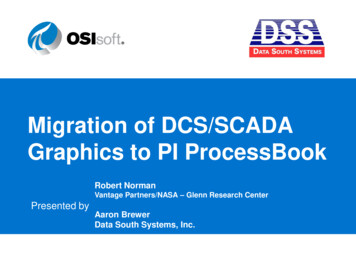
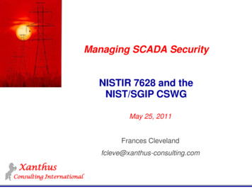
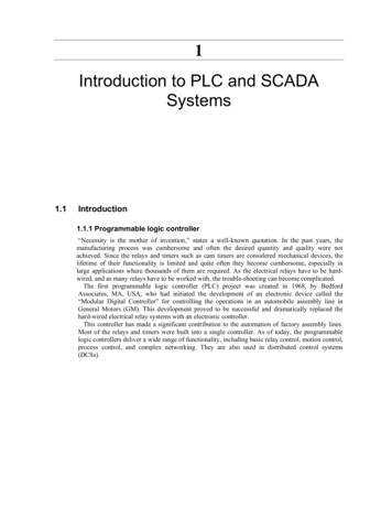
2 Practical Troubleshooting and Problem Solving of PLCs and SCADA Systems1.2PLC block diagram of componentsFigure 1.1PLC block diagramFigure 1.1 shows, in block form, the four major units of a PLC system and their interconnections,which are briefly described here:1.2.3.4.Central processing unit (CPU)This is called the “Brain” of the PLC system, and has the following three sub- units:(a) A microprocessor unit that carries out the mathematical and logical operationsof the system.(b) A memory unit in which the system software and the user program data andinformation are stored and retrieved.(c) Power supply, which is an electrical supply that converts the alternate current(AC) line voltage to various direct current (DC) operational values. In thisprocess, the power supply is filtered and regulated to a DC voltage to ensureproper operation of the PLC system.PLC programmer/monitorA programming device is used to communicate with the circuits of the PLC. Thismay be a hand-held terminal, industrial terminal, or a personal computer.I/O modules(a) The “I” is the input module, which has terminals into which outside processelectrical signals, generated by sensors or transducers, are entered. Thesesensors or transducers can be thousands of meters away from the CPU.(b) The “O” is the output module, which has terminals into which output signals aresent to activate relays, solenoids, various solid-state switching devices, motors,and displays. These output signaling elements may also be thousands of metersaway from the CPU.Sometimes, an electronic system for connecting I/O modules to remote locations canbe added as it is necessary.Racks and chassisThere is a rack on which the PLC parts are mounted and the enclosures on which theCPU, the PM, and the I/O modules are mounted.
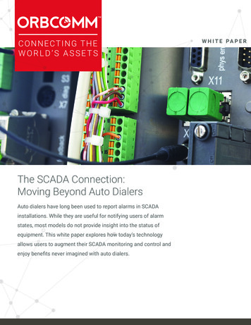
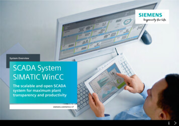
Introduction to PLC and SCADA Systems5.3Optional devices(a) Printer – it is a device using which the program in the CPU may be printed. Inaddition, operating information may be printed upon command.(b) Program recorder/player – PLCs use fluffy disks, with hard disks for secondarystorage. This recorder provides the backup and a way to download the programwritten-off from the PLC process system.(c) Master computers – they are often used to coordinate many individual,interconnected PLCs. These interconnected electrical buses are sometimesreferred to as “Data Highways.”1.2.1 Size of the PLC systemProgrammable logic controllers are classified on the basis of their size: A small system is one with 500 analog and digital I/Os. A medium system has I/Os ranging from 500 to 5,000. A system with 5,000 I/Os is considered large.1.2.2 Components of the PLC systemFigure 1.2 illustrates a sample PLC system and its components.Figure 1.2Typical PLC system components
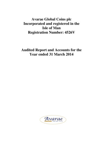
4 Practical Troubleshooting and Problem Solving of PLCs and SCADA SystemsThis is the actual system. How does it look like? Does it seem difficult to understand it? Let uscompare Figure 1.2, component by component, with Figure 1.3, which is its simplified version.Figure 1.3A typical PLC configuration1.3PLC power supplyA DC power supply is required by the PLC for low-level voltage used by the CPU, as well as forthe I/O and communication modules. More often than not, a separate power supply module mostlysupplies power. This is located beside the CPU unit or the external power supply, depending on thePLC vendor.The power supply available in most plants in 220 V AC, 120 V AC (60 Hz), or 24 V DC andmost PLCs operate on 5 V and 5 V DC. The conversion from 120 V AC to 5 V DC isaccomplished by a built-in voltage-converting power supply. Figure 1.4 illustrates this.Figure 1.4Power supply
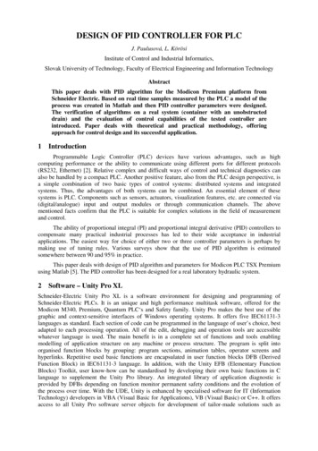
Introduction to PLC and SCADA Systems5As shown in Figure 1.4, there are five parts, including a switching system for the battery backupsystem:1.2.3.4.5.Line conditioner – This is either included in the PLC CPU or separate external unitaccording to CPU current rating. This AC conditioner purifies the AC waveform,because sometimes due to external factors, the sine wave form may be distorted. Theexternal factors are considered to be the sine wave distortion during switching orgeneration and by the electrical back surge from other electrical equipment in theplant.Converter/rectifier – It changes the bidirectional AC to a pulsating, unidirectionalDC waveform. Internally, a transformer steps down the voltage to an appropriatelevel. Then the bridge rectifier produces pulsating DC outputs. One output is 5 Vand the other is 5 V. This dual voltage is required to operate many of the IC chipsin the CPU.Filter – A computer needs a constant input DC voltage for correct operation. Thepulsating DC voltage is to be smoothened out. This is accomplished in the filtersection.Regulator – The regulator is always included in the circuit, to keep the voltage at ornear the 5 V levels regardless of load (CPU) demands.Battery backup system – The switch is set to switch the output from power supplyto battery backup power quickly and automatically if the input power fails whiledisconnecting the CPU plug or the plant power fails. The continuity of powervoltage keeps the user program from being lost. There is also some circuitry thatconverts battery DC (e.g., 24 V) to the two 5 V DC at required level.The voltage required depends on the type of chips used within the system. If TTL ICs are used, a5 V DC power supply will be required. If a CMOS type of IC is utilized, then the power supplywill be in the range of 3–18 V.Power is also required for operating field devices and output loads so that they may operate. Aseparate external power supply is provided for this purpose. It is often referred to as the fieldinterrogation power supply.The latter is kept separate from the control power supply so that any power supply problems inthe field are not echoed within the PLC.1.4PLC processor module and memoryThe processor or CPU is the heart of a PLC system. It will be referred to as the CPU from nowonward, for the sake of convenience. A typical processor card is shown in Figure 1.5.
6 Practical Troubleshooting and Problem Solving of PLCs and SCADA SystemsFigure 1.5The processor of a PLC (Courtesy: Allen-Bradley)The main processor (or CPU) is a microprocessor-based system that executes the controlprogram, after reading the status of the field inputs. It, in turn, sends commands to the field outputs.Depending on the manufacturer, it is possible to find bit or word processors. If a bit processor isused, it will only be able to control logic bit operations. A word processor can control both bit andword operations such as processing numerical data, calculations, and analog values. Nowadays,most processors are found to be of the word type.Does it appear as if something is missing? The CPU requires a power supply for its internalelectronics, as well as for operating the signal exchange with the I/O modules.That power supply is either derived from a separate external power supply, or some PLC unitsmay have a power supply card installed beside the CPU card.1.4.1 Features of the CPUNormally, one will find the following common features in any PLC CPU card.1.2.Operating key switches (mode)These switches are included to enable the user to select different modes of operationof the PLC system. Off/stop: If this mode is selected, the PLC cannot run or be programmed. Run: The PLC will run or execute the program, but modifying or changing theprogram is not possible. Program: Program execution is stopped and modification or deletion of programis possible.These features are generally present in each system, but may have minor differences.IndicationsIn order to know the current status of the CPU, some indication lights are given onthe front/face. Power: Indicates whether the CPU power supply is healthy. Run: Indicates whether a PLC is in run mode. Stop: Indicates whether a PLC is in stop mode. Fault: This will illuminate whenever there is any fault within the PLC – eitherin the software or in the hardware.
Introduction to PLC and SCADA Systems7 3.4.5.6.Program: Indicates the PLC has been selected in the program mode by meansof the selector switch. Communication: Depending on the communication options provided, thisindicates the health of a communication link.Programming portA programming port is provided on the CPU to download any user program from aprogramming device, to the CPU. The programming port is either a nine-pin serialCOM port or any other type depending on the vendor.Communication portCommunication ports are prerequisites in PLC units as the PLC must exchange datawith other PLCs (or operator stations) to show the process information. For thispurpose, different vendors provide different kinds of communication ports. As acommon practice, you will probably find an Ethernet port.BatteryA 3.6 V DC battery is normally given in a compartment on the CPU itself formemory backup in case of a power failure.Memory chipIn some PLCs, such as those from Siemens, an external flash EEPROM card isprovided in slot on the CPU for user program backup storage.The CPU’s memory contains the manufacturer’s operating system and housekeepingfunctions, the program written by the user, and the data stored by the user, relating tothe process or the equipment being controlled.The memory chip is the main component of the PLC processor unit. It will bediscussed in more detail in the next chapter.These are the general features that can be found on the PLC’s CPU cards. However,some CPUs may offer other additional features as well, relating to the workingrequirements.1.4.2 Working of a PLC CPUThe operation of a CPU is very similar to the operation of the PLC itself. This is due to the fact thatthe CPU is the brain, where everything occurs.Figure 1.6 will indicate this more clearly.Figure 1.6Working of a PLC CPUA PLC uses input modules (analog or digital) for collecting field data. Then, during programexecution (which goes on continuously), it generates output commands depending on the inputfield data. These output commands are sent to the field via output (analog or digital) modules.In order to do this, the PLC has the following four stages of operation that are continuouslyrepeated, many times per second (i.e., the CPU’s scan rate).
8 Practical Troubleshooting and Problem Solving of PLCs and SCADA Systems Self-test: This checks for hardware and software errors of the PLC.Input scan: This reads the status of inputs from the cards and transfers values tomemory. It can be equated to taking snaps of the inputs. In some cases (such as withanalog inputs), they are not stored in memory.Logic solving: A program is executed on the basis of the input status stored in thememory. Thus, the outputs are decided and transferred to the memory.Output scan: The outputs are transferred from the memory to the physical cards.Why is an input or output scan required? Why can’t the PLC take the status of inputs directly allthe time and send this information directly to the cards?Visualize a condition where an input (which is used or accessed in logic format at multiplelocations) changes state, while the program is halfway through its execution. What’s going tohappen? This will invalidate the logic. To avoid this situation, input and output scans are done sothat once the input status is copied in the memory it remains valid throughout that programexecution cycle.Other than this, it is important to note that data access with I/O modules is done through acommunication data bus (back plane connector).The CPU has a PG port. This is used to feed the PLC program by means of the programmingdevice.1.4.3 Memory systemsThe memory system is an integral and very important part of any PLC system. There are two broadsections of PLC memory: Internal memoryExternal memory“Internal memory” is the memory within the PLC; that is, the user accessible memory (RAM). Itis an integral part of each PLC.“External memory” is the memory outside the PLC; that is, generally the EPROM or EEPROM.It is an optional part of any PLC, and is dependent on the vendor.The functions of user-accessible memory and its various types will now be discussed in detail.Internal or user accessible memory (RAM)Internal or user accessible memory (RAM) has the following functions: Storing the user PLC program.Storing the status of inputs and outputs.Storing timer, counter, and register values.Figure 1.7 describes this section of memory.
Introduction to PLC and SCADA Systems9Figure 1.7Sections of PLC RAM memoryAs shown in
1.2 PLC block diagram of components Figure 1.1 PLC block diagram Figure 1.1 shows, in block form, the four major units of a PLC system and their interconnections, which are briefly described here: 1. Central processing unit (CPU) This is called the “Brain” of the PLC system, and has the following three sub- units: (a) A microprocessor unit that carries out the mathematical and logical .