Transcription
ABB machinery drivesSupplementWinder control program for ACSM1 drives
Related manualsDrive manualsACSM1-04 (0.75 to 45 kW) Drive Modules Hardware Manual*ACSM1-04 (55 to 110 kW) Drive Modules Hardware Manual*ACSM1-04LC (55 to 132 kW) Liquid-Cooled Drive Modules HardwareManual*ACSM1 Motion Control Program Firmware ManualACSM1 Speed and Torque Control Program Firmware ManualCode FE688482703AFE688482612)2)Drive PC tool manualsDriveStudio User ManualDriveSPC User Manual3AFE687490263AFE68836590Option manuals and guidesACSM1 Control Panel User's GuideFCAN-01 CANopen Adapter Module User’s ManualFDNA-01 DeviceNet Adapter Module User’s ManualFECA-01 EtherCAT Adapter Module User's ManualFEN-01 TTL Encoder Interface User’s Manual*FEN-11 Absolute Encoder Interface User’s Manual*FEN-21 Resolver Interface User’s Manual*FEN-31 HTL Encoder Interface User’s Manual*FENA-01 Ethernet Adapter Module Hardware ManualFENA-01 Ethernet Adapter Module Ethernet/IP Protocol ManualFENA-01 Ethernet Adapter Module Modbus/TCP Protocol ManualFIO-01 Digital I/O Extension User’s Manual*FIO-11 Analog I/O Extension User’s Manual*FIO-21 Analog I/O Extension User’s Manual*FMBA-01 Modbus adapter module User's manualFPBA-01 PROFIBUS DP Adapter Module User’s vered as a printed copy with the option.2)Delivered by the Marketing Material Order Service on request (https://order.hansaprint.fi/abb/).*A multilingual quick installation guide is included with the delivery.All manuals are available in PDF format on the Internet. See section Document library on the Internet on page 10.
Winder control program for ACSM1 drivesSupplement3AUA0000031510 REV CENEFFECTIVE: 2010-08-16 2010 ABB Oy. All Rights Reserved.
5Table of contentsRelated manuals . . . . . . . . . . . . . . . . . . . . . . . . . . . . . . . . . . . . . . . . . . . . . . . . . . . . . . . . . . . . . . . . 2Table of contentsIntroduction to this supplementWhat this chapter contains . . . . . . . . . . . . . . . . . . . . . . . . . . . . . . . . . . . . . . . . . . . . . . . . . . . . . . . . 9Compatibility . . . . . . . . . . . . . . . . . . . . . . . . . . . . . . . . . . . . . . . . . . . . . . . . . . . . . . . . . . . . . . . . . . . 9Safety instructions . . . . . . . . . . . . . . . . . . . . . . . . . . . . . . . . . . . . . . . . . . . . . . . . . . . . . . . . . . . . . . . 9Intended audience . . . . . . . . . . . . . . . . . . . . . . . . . . . . . . . . . . . . . . . . . . . . . . . . . . . . . . . . . . . . . . . 9Contents . . . . . . . . . . . . . . . . . . . . . . . . . . . . . . . . . . . . . . . . . . . . . . . . . . . . . . . . . . . . . . . . . . . . . 10Product and service inquiries . . . . . . . . . . . . . . . . . . . . . . . . . . . . . . . . . . . . . . . . . . . . . . . . . . . . . 10Product training . . . . . . . . . . . . . . . . . . . . . . . . . . . . . . . . . . . . . . . . . . . . . . . . . . . . . . . . . . . . . . . . 10Providing feedback on ABB Drives manuals . . . . . . . . . . . . . . . . . . . . . . . . . . . . . . . . . . . . . . . . . . 10Document library on the Internet . . . . . . . . . . . . . . . . . . . . . . . . . . . . . . . . . . . . . . . . . . . . . . . . . . . 10Application overviewWhat this chapter contains . . . . . . . . . . . . . . . . . . . . . . . . . . . . . . . . . . . . . . . . . . . . . . . . . . . . . . .Winder control . . . . . . . . . . . . . . . . . . . . . . . . . . . . . . . . . . . . . . . . . . . . . . . . . . . . . . . . . . . . . . . . .Winder/Unwinder . . . . . . . . . . . . . . . . . . . . . . . . . . . . . . . . . . . . . . . . . . . . . . . . . . . . . . . . . . . .Infeeder . . . . . . . . . . . . . . . . . . . . . . . . . . . . . . . . . . . . . . . . . . . . . . . . . . . . . . . . . . . . . . . . . . .Line speed . . . . . . . . . . . . . . . . . . . . . . . . . . . . . . . . . . . . . . . . . . . . . . . . . . . . . . . . . . . . . . . . .Roll diameter . . . . . . . . . . . . . . . . . . . . . . . . . . . . . . . . . . . . . . . . . . . . . . . . . . . . . . . . . . . . . . .Tension control . . . . . . . . . . . . . . . . . . . . . . . . . . . . . . . . . . . . . . . . . . . . . . . . . . . . . . . . . . . . . .OPEN LOOP . . . . . . . . . . . . . . . . . . . . . . . . . . . . . . . . . . . . . . . . . . . . . . . . . . . . . . . . . . . . .OPEN LOOP TENSION control diagram . . . . . . . . . . . . . . . . . . . . . . . . . . . . . . . . . . . . . . . .TENSION TORQUE TRIM . . . . . . . . . . . . . . . . . . . . . . . . . . . . . . . . . . . . . . . . . . . . . . . . . . .TENSION TORQUE TRIM control diagram . . . . . . . . . . . . . . . . . . . . . . . . . . . . . . . . . . . . . .TENSION SPEED TRIM . . . . . . . . . . . . . . . . . . . . . . . . . . . . . . . . . . . . . . . . . . . . . . . . . . . .TENSION SPEED TRIM control diagram . . . . . . . . . . . . . . . . . . . . . . . . . . . . . . . . . . . . . . .DANCER SPEED TRIM . . . . . . . . . . . . . . . . . . . . . . . . . . . . . . . . . . . . . . . . . . . . . . . . . . . . .DANCER SPEED TRIM control diagram . . . . . . . . . . . . . . . . . . . . . . . . . . . . . . . . . . . . . . . .Automatic roll change . . . . . . . . . . . . . . . . . . . . . . . . . . . . . . . . . . . . . . . . . . . . . . . . . . . . . . . . .Expandability and adaptivity . . . . . . . . . . . . . . . . . . . . . . . . . . . . . . . . . . . . . . . . . . . . . . . . . . . .1111111212131313141516171819202121Start-upWhat this chapter contains . . . . . . . . . . . . . . . . . . . . . . . . . . . . . . . . . . . . . . . . . . . . . . . . . . . . . . . 23How to commission the application . . . . . . . . . . . . . . . . . . . . . . . . . . . . . . . . . . . . . . . . . . . . . . . . . 23Default control connectionsWhat this chapter contains . . . . . . . . . . . . . . . . . . . . . . . . . . . . . . . . . . . . . . . . . . . . . . . . . . . . . . . 27Table of contents
6Actual signals and parametersWhat this chapter contains . . . . . . . . . . . . . . . . . . . . . . . . . . . . . . . . . . . . . . . . . . . . . . . . . . . . . . . 29Terms and abbreviations . . . . . . . . . . . . . . . . . . . . . . . . . . . . . . . . . . . . . . . . . . . . . . . . . . . . . . . . 2905 WINDER ACT SIGNALS . . . . . . . . . . . . . . . . . . . . . . . . . . . . . . . . . . . . . . . . . . . . . . . . . . . . . . .3040 FLUX CONTROL . . . . . . . . . . . . . . . . . . . . . . . . . . . . . . . . . . . . . . . . . . . . . . . . . . . . . . . . . . . . .3280 WINDER CONTROL . . . . . . . . . . . . . . . . . . . . . . . . . . . . . . . . . . . . . . . . . . . . . . . . . . . . . . . . . .3281 WINDER REF MOD . . . . . . . . . . . . . . . . . . . . . . . . . . . . . . . . . . . . . . . . . . . . . . . . . . . . . . . . . .3582 DIAMETER CALC . . . . . . . . . . . . . . . . . . . . . . . . . . . . . . . . . . . . . . . . . . . . . . . . . . . . . . . . . . . .3683 TEN & DAN CTRL . . . . . . . . . . . . . . . . . . . . . . . . . . . . . . . . . . . . . . . . . . . . . . . . . . . . . . . . . . . .3884 INERTIA COMP . . . . . . . . . . . . . . . . . . . . . . . . . . . . . . . . . . . . . . . . . . . . . . . . . . . . . . . . . . . . .4085 FRICTION COMP . . . . . . . . . . . . . . . . . . . . . . . . . . . . . . . . . . . . . . . . . . . . . . . . . . . . . . . . . . . .4286 TORQ MEM CTRL . . . . . . . . . . . . . . . . . . . . . . . . . . . . . . . . . . . . . . . . . . . . . . . . . . . . . . . . . . .43Fieldbus controlWhat this chapter contains . . . . . . . . . . . . . . . . . . . . . . . . . . . . . . . . . . . . . . . . . . . . . . . . . . . . . . .Supported fieldbus profiles . . . . . . . . . . . . . . . . . . . . . . . . . . . . . . . . . . . . . . . . . . . . . . . . . . . . . . .FBA reference 1 / FBA actual signal 1 . . . . . . . . . . . . . . . . . . . . . . . . . . . . . . . . . . . . . . . . . . . . . .PROFIdrive scaling . . . . . . . . . . . . . . . . . . . . . . . . . . . . . . . . . . . . . . . . . . . . . . . . . . . . . . . . . .ABB Drives scaling . . . . . . . . . . . . . . . . . . . . . . . . . . . . . . . . . . . . . . . . . . . . . . . . . . . . . . . . . .FBA reference 2 / FBA actual signal 2 . . . . . . . . . . . . . . . . . . . . . . . . . . . . . . . . . . . . . . . . . . . . . .PROFIdrive and ABB Drives scaling . . . . . . . . . . . . . . . . . . . . . . . . . . . . . . . . . . . . . . . . . . . . .Control and status . . . . . . . . . . . . . . . . . . . . . . . . . . . . . . . . . . . . . . . . . . . . . . . . . . . . . . . . . . . . .Example of settings for the PROFIBUS . . . . . . . . . . . . . . . . . . . . . . . . . . . . . . . . . . . . . . . . . . . . .454545454545464646Technology function blocks and custom circuitsWhat this chapter contains . . . . . . . . . . . . . . . . . . . . . . . . . . . . . . . . . . . . . . . . . . . . . . . . . . . . . . .General . . . . . . . . . . . . . . . . . . . . . . . . . . . . . . . . . . . . . . . . . . . . . . . . . . . . . . . . . . . . . . . . . . . . . .Technology block and custom circuit layout . . . . . . . . . . . . . . . . . . . . . . . . . . . . . . . . . . . . . . .Actual signals . . . . . . . . . . . . . . . . . . . . . . . . . . . . . . . . . . . . . . . . . . . . . . . . . . . . . . . . . . . . . . .Parameters . . . . . . . . . . . . . . . . . . . . . . . . . . . . . . . . . . . . . . . . . . . . . . . . . . . . . . . . . . . . . . . .Terms in the parameter/signal tables . . . . . . . . . . . . . . . . . . . . . . . . . . . . . . . . . . . . . . . . . . . . . . .Fieldbus equivalent . . . . . . . . . . . . . . . . . . . . . . . . . . . . . . . . . . . . . . . . . . . . . . . . . . . . . . . . . . . .Fieldbus addresses . . . . . . . . . . . . . . . . . . . . . . . . . . . . . . . . . . . . . . . . . . . . . . . . . . . . . . . . . . . .Pointer parameter format in fieldbus communication . . . . . . . . . . . . . . . . . . . . . . . . . . . . . . . . . . .32-bit integer value pointers . . . . . . . . . . . . . . . . . . . . . . . . . . . . . . . . . . . . . . . . . . . . . . . . . . .32-bit integer bit pointers . . . . . . . . . . . . . . . . . . . . . . . . . . . . . . . . . . . . . . . . . . . . . . . . . . . . . .List of technology function blocks and custom circuits . . . . . . . . . . . . . . . . . . . . . . . . . . . . . . . . . .DIA CALC . . . . . . . . . . . . . . . . . . . . . . . . . . . . . . . . . . . . . . . . . . . . . . . . . . . . . . . . . . . . . . . . . . . .Description . . . . . . . . . . . . . . . . . . . . . . . . . . . . . . . . . . . . . . . . . . . . . . . . . . . . . . . . . . . . . . . . .Inputs . . . . . . . . . . . . . . . . . . . . . . . . . . . . . . . . . . . . . . . . . . . . . . . . . . . . . . . . . . . . . . . . . . . . .Outputs . . . . . . . . . . . . . . . . . . . . . . . . . . . . . . . . . . . . . . . . . . . . . . . . . . . . . . . . . . . . . . . . . . .FRICTION COMP . . . . . . . . . . . . . . . . . . . . . . . . . . . . . . . . . . . . . . . . . . . . . . . . . . . . . . . . . . . . . .Description . . . . . . . . . . . . . . . . . . . . . . . . . . . . . . . . . . . . . . . . . . . . . . . . . . . . . . . . . . . . . . . . .Inputs . . . . . . . . . . . . . . . . . . . . . . . . . . . . . . . . . . . . . . . . . . . . . . . . . . . . . . . . . . . . . . . . . . . . .Outputs . . . . . . . . . . . . . . . . . . . . . . . . . . . . . . . . . . . . . . . . . . . . . . . . . . . . . . . . . . . . . . . . . . .INERTIA COMP . . . . . . . . . . . . . . . . . . . . . . . . . . . . . . . . . . . . . . . . . . . . . . . . . . . . . . . . . . . . . . .Description . . . . . . . . . . . . . . . . . . . . . . . . . . . . . . . . . . . . . . . . . . . . . . . . . . . . . . . . . . . . . . . . .Table of 60
7Inputs . . . . . . . . . . . . . . . . . . . . . . . . . . . . . . . . . . . . . . . . . . . . . . . . . . . . . . . . . . . . . . . . . . . . .Outputs . . . . . . . . . . . . . . . . . . . . . . . . . . . . . . . . . . . . . . . . . . . . . . . . . . . . . . . . . . . . . . . . . . . .TEN&DAN CTRL . . . . . . . . . . . . . . . . . . . . . . . . . . . . . . . . . . . . . . . . . . . . . . . . . . . . . . . . . . . . . . .Description . . . . . . . . . . . . . . . . . . . . . . . . . . . . . . . . . . . . . . . . . . . . . . . . . . . . . . . . . . . . . . . . .Inputs . . . . . . . . . . . . . . . . . . . . . . . . . . . . . . . . . . . . . . . . . . . . . . . . . . . . . . . . . . . . . . . . . . . . .Outputs . . . . . . . . . . . . . . . . . . . . . . . . . . . . . . . . . . . . . . . . . . . . . . . . . . . . . . . . . . . . . . . . . . . .NCTRLTORQLIMSEL . . . . . . . . . . . . . . . . . . . . . . . . . . . . . . . . . . . . . . . . . . . . . . . . . . . . . . . . . . .Description . . . . . . . . . . . . . . . . . . . . . . . . . . . . . . . . . . . . . . . . . . . . . . . . . . . . . . . . . . . . . . . . .Inputs . . . . . . . . . . . . . . . . . . . . . . . . . . . . . . . . . . . . . . . . . . . . . . . . . . . . . . . . . . . . . . . . . . . . .Outputs . . . . . . . . . . . . . . . . . . . . . . . . . . . . . . . . . . . . . . . . . . . . . . . . . . . . . . . . . . . . . . . . . . . .TEN2SPD . . . . . . . . . . . . . . . . . . . . . . . . . . . . . . . . . . . . . . . . . . . . . . . . . . . . . . . . . . . . . . . . . . . .Description . . . . . . . . . . . . . . . . . . . . . . . . . . . . . . . . . . . . . . . . . . . . . . . . . . . . . . . . . . . . . . . . .Inputs . . . . . . . . . . . . . . . . . . . . . . . . . . . . . . . . . . . . . . . . . . . . . . . . . . . . . . . . . . . . . . . . . . . . .Outputs . . . . . . . . . . . . . . . . . . . . . . . . . . . . . . . . . . . . . . . . . . . . . . . . . . . . . . . . . . . . . . . . . . . .TEN2TORQ . . . . . . . . . . . . . . . . . . . . . . . . . . . . . . . . . . . . . . . . . . . . . . . . . . . . . . . . . . . . . . . . . . .Description . . . . . . . . . . . . . . . . . . . . . . . . . . . . . . . . . . . . . . . . . . . . . . . . . . . . . . . . . . . . . . . . .Inputs . . . . . . . . . . . . . . . . . . . . . . . . . . . . . . . . . . . . . . . . . . . . . . . . . . . . . . . . . . . . . . . . . . . . .Outputs . . . . . . . . . . . . . . . . . . . . . . . . . . . . . . . . . . . . . . . . . . . . . . . . . . . . . . . . . . . . . . . . . . . .TORQMEM . . . . . . . . . . . . . . . . . . . . . . . . . . . . . . . . . . . . . . . . . . . . . . . . . . . . . . . . . . . . . . . . . . .Description . . . . . . . . . . . . . . . . . . . . . . . . . . . . . . . . . . . . . . . . . . . . . . . . . . . . . . . . . . . . . . . . .Inputs . . . . . . . . . . . . . . . . . . . . . . . . . . . . . . . . . . . . . . . . . . . . . . . . . . . . . . . . . . . . . . . . . . . . .Outputs . . . . . . . . . . . . . . . . . . . . . . . . . . . . . . . . . . . . . . . . . . . . . . . . . . . . . . . . . . . . . . . . . . . .WEBLOSS . . . . . . . . . . . . . . . . . . . . . . . . . . . . . . . . . . . . . . . . . . . . . . . . . . . . . . . . . . . . . . . . . . . .Description . . . . . . . . . . . . . . . . . . . . . . . . . . . . . . . . . . . . . . . . . . . . . . . . . . . . . . . . . . . . . . . . .Inputs . . . . . . . . . . . . . . . . . . . . . . . . . . . . . . . . . . . . . . . . . . . . . . . . . . . . . . . . . . . . . . . . . . . . .Outputs . . . . . . . . . . . . . . . . . . . . . . . . . . . . . . . . . . . . . . . . . . . . . . . . . . . . . . . . . . . . . . . . . . . .WINDERCTRL . . . . . . . . . . . . . . . . . . . . . . . . . . . . . . . . . . . . . . . . . . . . . . . . . . . . . . . . . . . . . . . .Description . . . . . . . . . . . . . . . . . . . . . . . . . . . . . . . . . . . . . . . . . . . . . . . . . . . . . . . . . . . . . . . . .Inputs . . . . . . . . . . . . . . . . . . . . . . . . . . . . . . . . . . . . . . . . . . . . . . . . . . . . . . . . . . . . . . . . . . . . .Outputs . . . . . . . . . . . . . . . . . . . . . . . . . . . . . . . . . . . . . . . . . . . . . . . . . . . . . . . . . . . . . . . . . . . .WINDERREFMOD . . . . . . . . . . . . . . . . . . . . . . . . . . . . . . . . . . . . . . . . . . . . . . . . . . . . . . . . . . . . .Description . . . . . . . . . . . . . . . . . . . . . . . . . . . . . . . . . . . . . . . . . . . . . . . . . . . . . . . . . . . . . . . . .Inputs . . . . . . . . . . . . . . . . . . . . . . . . . . . . . . . . . . . . . . . . . . . . . . . . . . . . . . . . . . . . . . . . . . . . .Outputs . . . . . . . . . . . . . . . . . . . . . . . . . . . . . . . . . . . . . . . . . . . . . . . . . . . . . . . . . . . . . . . . . . . .WINDERSTALL . . . . . . . . . . . . . . . . . . . . . . . . . . . . . . . . . . . . . . . . . . . . . . . . . . . . . . . . . . . . . . . .Description . . . . . . . . . . . . . . . . . . . . . . . . . . . . . . . . . . . . . . . . . . . . . . . . . . . . . . . . . . . . . . . . .Inputs . . . . . . . . . . . . . . . . . . . . . . . . . . . . . . . . . . . . . . . . . . . . . . . . . . . . . . . . . . . . . . . . . . . . .Outputs . . . . . . . . . . . . . . . . . . . . . . . . . . . . . . . . . . . . . . . . . . . . . . . . . . . . . . . . . . . . . . . . . . . .FLUX CTRL . . . . . . . . . . . . . . . . . . . . . . . . . . . . . . . . . . . . . . . . . . . . . . . . . . . . . . . . . . . . . . . . . . .Description . . . . . . . . . . . . . . . . . . . . . . . . . . . . . . . . . . . . . . . . . . . . . . . . . . . . . . . . . . . . . . . . .Inputs . . . . . . . . . . . . . . . . . . . . . . . . . . . . . . . . . . . . . . . . . . . . . . . . . . . . . . . . . . . . . . . . . . . . .Outputs . . . . . . . . . . . . . . . . . . . . . . . . . . . . . . . . . . . . . . . . . . . . . . . . . . . . . . . . . . . . . . . . . . . 57576767676777778787980808081818282Fault tracingWhat this chapter contains . . . . . . . . . . . . . . . . . . . . . . . . . . . . . . . . . . . . . . . . . . . . . . . . . . . . . . .Safety . . . . . . . . . . . . . . . . . . . . . . . . . . . . . . . . . . . . . . . . . . . . . . . . . . . . . . . . . . . . . . . . . . . . . . .Alarm and fault indications . . . . . . . . . . . . . . . . . . . . . . . . . . . . . . . . . . . . . . . . . . . . . . . . . . . . . . .How to reset . . . . . . . . . . . . . . . . . . . . . . . . . . . . . . . . . . . . . . . . . . . . . . . . . . . . . . . . . . . . . . . . . .Fault history . . . . . . . . . . . . . . . . . . . . . . . . . . . . . . . . . . . . . . . . . . . . . . . . . . . . . . . . . . . . . . . . . . .8383838384Table of contents
8Alarm messages . . . . . . . . . . . . . . . . . . . . . . . . . . . . . . . . . . . . . . . . . . . . . . . . . . . . . . . . . . . . . . . 85Fault messages . . . . . . . . . . . . . . . . . . . . . . . . . . . . . . . . . . . . . . . . . . . . . . . . . . . . . . . . . . . . . . . 85Control block diagramsWhat this chapter contains . . . . . . . . . . . . . . . . . . . . . . . . . . . . . . . . . . . . . . . . . . . . . . . . . . . . . . . 87Appendix A: Motor rotor inertia, IECTable of contents
9Introduction to this supplementThis document is a supplement to ACSM1 Speed and Torque Control ProgramFirmware Manual (3AFE68848261 [English]). The supplement covers actual signals,parameters, technology function blocks, custom circuits as well as fault and alarmmessages related to the winder control program. For other information, refer to theFirmware Manual.What this chapter containsThe chapter includes a description of the contents of the supplement. In addition, itcontains information about the compatibility, safety and intended audience.CompatibilityThe supplement is compatible with the winder control program for ACSM1 drives(Version UAWI1100 and above).Safety instructionsFollow all safety instructions delivered with the drive. Read the complete safety instructions before you install, commission, or usethe drive. The complete safety instructions are given at the beginning of the driveHardware Manual (see the list of related manuals on the inside of the front cover,page 2). Read the winder control program specific warnings and notes beforechanging the default settings of the parameters and functions. For eachparameter, the warnings and notes are given in chapter Actual signals andparameters. Read the firmware function block specific warnings and notes beforechanging the default settings of the function. For each firmware function block,the warnings and notes are given in the drive Firmware Manual in the sectiondescribing the related user-adjustable parameters.Intended audienceThe reader of the supplement is expected to: know the standard electrical wiring practices, electronic components andelectrical schematic symbols have a firm understanding of winding and unwinding principles.Introduction to this supplement
10ContentsThe supplement consists of the following chapters: Introduction to this supplement describes the contents of this manual. Application overview gives a brief overview of the winder application and relatedterms. Start-up gives instructions for commissioning the winder application. Default control connections shows the default control connections of the JCUControl Unit. Actual signals and parameters describes the actual signals and parameters of thewinder application. Technology function blocks and custom circuits describes the technology functionblocks and custom circuits and lists the associated input and output parametersand signals. Fault tracing lists the alarms and fault messages with the possible causes andremedies. Control block diagrams presents the application program pages containing thewinder control program technology blocks and custom circuits. Appendix A: Motor rotor inertia, IEC gives an example of common inverter dutyAC motor rotor inertia.Product and service inquiriesAddress any inquiries about the product to your local ABB representative, quotingthe type designation and serial number of the unit in question. A listing of ABB sales,support and service contacts can be found by navigating to www.abb.com/drives andselecting Sales, Support and Service Network.Product trainingFor information on ABB product training, navigate to www.abb.com/drives and selectTraining courses.Providing feedback on ABB Drives manualsYour comments on our manuals are welcome. Go to www.abb.com/drives and selectDocument Library – Manuals feedback form (LV AC drives).Document library on the InternetYou can find manuals and other product documents in PDF format on the Internet.Go to www.abb.com/drives and select Document Library. You can browse the libraryor enter selection criteria, for example a document code, in the search field.Introduction to this supplement
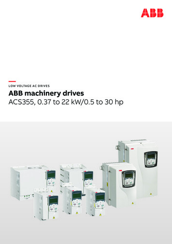
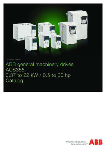
11Application overviewWhat this chapter containsThe chapter includes a brief overview of the winder application and related terms.Winder controlAn example of a process with winders is shown in the figure below.DancerWebUnwinderWinderNIPV/mARoll SpindleCoreABB DriveABB DriveV/mAABB DriveLoadcell Example of a process with windersWinder/UnwinderA winder is used to wind material (web) around the core or from the roll, dependingon the wanted direction. Material is taken out of the roll with an unwinder and woundto the core with a winder.The winder control program is used to calculate the diameter of the roll, control theweb tension and line speed according to the user given references. An overview ofthe winder control is shown in the figure on page 12. Each tension control mode isexplained more thoroughly later with the help of control diagrams.Application overview
12AI1AI2FBD2DENC1ENC283 TEN & Torque reference additionDAN CTRL34 REF20 LIMITS*ERENCECTRL*83 TEN &DAN CTRL85 FRICTIONCOMP40 MOTOR CONTROL*MPID Speed controller torque limitsAI1AI2FBD2DENC1ENC224 SPEEDREF MOD*81 WINDER REFMOD25 SPEEDREFRAMP*26 SPEEDERROR*26.08 ACCCOMPDERTIME*82 DIAMETER CALC28 SPEEDCONTROL*PIDEENC1ENC222 SPEED FEEDBACK*84 INERTIA COMP* Index of the parameter/group in ACSM1;may be different in other drives.Winder control overviewInfeederInfeeder (eg, NIP or pinch roll) is a process control section used to help transportmaterial in the process line. For an infeeder, the roll diameter is fixed and thediameter calculation can be disabled. An infeeder can be tension controlled or purelyspeed controlled. The winder control program can also be used in infeederapplications.Line speedLine speed is the operational speed of the controlled process, given in meters persecond. Because for winders and unwinders the roll radius is changing, the speedreference to the motor has to be modified according to the actual radius of the drivenroll.Related parameter groups: 80 WINDER CONTROL 81 WINDER REF MOD.Application overview
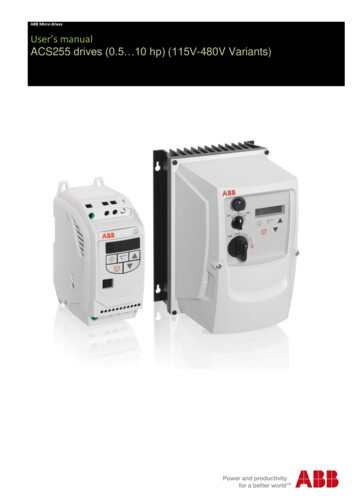
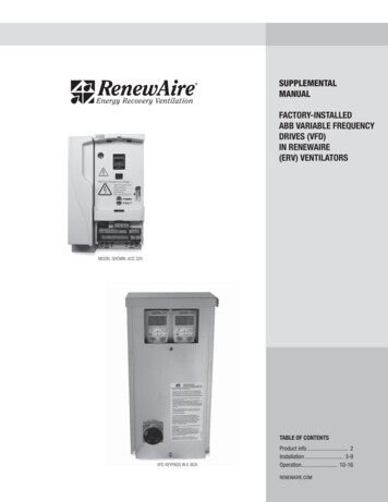
13Roll diameterThe winder control program uses the line speed reference and actual roll rpm tocalculate the roll diameter. To stabilize the calculation, the actual diameter is rampedaccording to the web thickness. The roll diameter calculation is based upon internalcalculations where no external device is needed; however, the use of an externaldiameter sensor is available. This aids in stopping and restarting partial rolls withminimal tension disturbances.For an NIP or pinch roll (infeeders), the diameter of the driven roll does not change,so that the diameter calculation can be disabled.Related parameter group: 82 DIAMETER CALC.Tension controlThe objective of the tension control is to maintain the tension of the web, ie, the forceapplied to the web. The motor speed and torque must change as a function of theweb speed and roll diameter.Motor torque Tension reference Roll radiusThe following tension control modes are available:OPEN LOOPFeedback from the web is not required in this mode. The tension of the web iscontrolled by calculating the torque reference of the motor, which is the product ofthe user-given tension reference and the actual roll radius. The tension control PIDis disabled. Inertia and friction compensation can be used to improve the tensioncontrol accuracy.The drive is running as speed controlled; the torque limits of the speed controller arecontrolled by the tension control. To ensure that the drive is always running againstthe calculated speed controller torque limits, the application adds an overspeedreference to the final speed reference. The amount of overspeed reference isadaptable with parameters.Since tension feedback from the web is not available, accurate web data is aprerequisite for successful tension control. Therefore, the friction and inertiacompensation should be set up carefully when the OPEN LOOP tension control isused.The OPEN LOOP tension control is suitable especially for non-stretchy materialswhich do not set extremely high requirements for the tension.See OPEN LOOP TENSION control diagram on page 14.Application overview
Application overview 5 - %6 -" " 5 !- !5 - % ! !5 -6 5 !- 5 !- %4" 5 !- !" # %"& ' ! ! " %4" 3 " 3 " " "% - -- 3 ) "% - 89 ! !" - % 6%"& " :%%;' " !5 "- - "% - - "- "% "!! 3 - 4 8 - !9 &- " "% - " 5 - " !5 "- - ! " "!! "- " ! "- - % "!! 3 - "!-5" "% - ) " ! % ) "% - "!- ( ) 3 ! !" # %"& - ' ), "% - ! ) ) /! " ) "!- ), "% - ! ) "% - "!- ) ! - % " ! % ) "!! - % " ! % * * !- % ! " !" ! % - ! % "- 8 !" !5 "- 3 " !- ! % "- - 15 - % * 3 - 4 - - ! - " !- - - 15 % - - ! - * !- 7 - 15 " - - - 15 ! ! " - ! % "- - - 15 "!! "- " ! "- ( * * * * ( * * * 6 " ! ! " -" - " 3 ! - % - - ! - "8 8 !"5 - - 6 " ! 8"!9 % - ! ). "% - "- ( )( "% ) "!- ( ) "% ) 6 ) 7 * * 0 7 - - ! - !" - ! - - % - - 15 " !" !5 "- - - 15 % - - ! - * * 0 2 !- ! % - ! % - % , - " ! % "- 8" - 15 " - - 15 ! " ( * ( ( - 1 - * ( ) - 1 !- * ( ), - - 1 % !- ( ). "!! ! % - 114OPEN LOOP TENSION control diagram
15TENSION TORQUE TRIMLoad cell feedback is required. Tension of the web is controlled by calculating thetorque reference of the motor, which is the product of the user-given tensionreference and the actual roll radius. In addition, the tension control PID modifies thefinal motor torque reference based on the tension feedback from the load cell.Inertia and friction compensation can be used to improve the tension controlaccuracy.The drive is running as speed controlled; the torque limits of the speed controller arecontrolled by the tension control. To ensure that the drive is always running againstthe calculated speed controller torque limits, the application adds an overspeedreference to the final speed reference. The amount of overspeed reference isadaptable with parameters. Accurate web material information is required.The TENSION TORQUE TRIM tension control may resul
The winder control program is used to calculate the diameter of the roll, control the web tension and line speed according to the user given references. An overview of the winder control is shown in the figure on page 12. Each tension control mode is explained more thoroughly later with the help of control diagrams. Roll NIP Winder Core Web .