Transcription
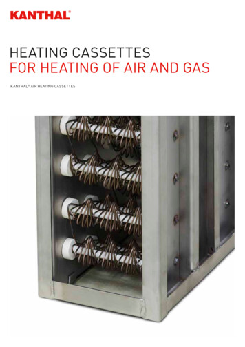
SR Heating Cable Design for Roof and Gutter ApplicationsGENERAL INFORMATION1. SR cable is designed to remove ice, not accumulatedsnow.2. SR cable will not keep snow or ice from falling off of theroof. Snow fences or snow guards should be used toeliminate snow movement.3. SR heating cables may be used on:- Roofs made from all types of roofing materials, such asshake, shingle, rubber, tar, wood, metal, and plastic.- Gutters made from standard materials, such as metaland plastic.- Downspouts made from standard materials, such as metaland plastic.4. Do not install the heating cable underneath any roofcovering.5. Install only in accessible locations; do not install behindwalls or where the cable would be hidden.6. Do not run the heating cable through walls, ceilings, orfloors.7. Connect only to ground-fault protected circuit breakers oroutlets that have been installed in accordance with allnational and local codes and standards and that areprotected from rain and other water sources such asmelting ice water.8. Do not exceed the amp rating of the over currentprotection device.Selecting the Required Heating Cable Length for Roof and Gutter DeicingCALCULATION FOR HEATING CABLE LENGTH:Use the formula below to determine the amount of heatingcable required.Total heating cable length A B C D E F GA (Roof edge) (heating cable multiplier)B (Roof edge x 0.5)C (Total gutter length)D (Total downspout length 1 ft)E (1 ft for each power connection)F (2 ft for each splice)G (3 ft for each tee connection) Total heating cable length requiredStandardRoofMetal Roof18” SeamMetal Roof24” 4.84.33.6Table 6: Heating Cable MultiplierUse the number in the table and multiply it by the length of the roof edge.CALCULATIONS FOR GUTTERS, DOWNSPOUT AND VALLEYS:1. For standard non-metal roofs, add 1 foot of heating cable foreach foot of gutter.Example:1.2.3.4.5.6.EaveOverhangRoof edge 48 ftEave overhang 1 ft (Refer to Table 6)Gutter 48 ftDownspout 22 ftPower connection 2 eachSplice 3 each2.Add 1 foot of heating cable per foot of downspout.3.If the downspout is in the middle of the run, loop the cabledown and back up. Double the length of the downspout fordetermining the length of cable to install.4.For valleys, run the heating cable two thirds of the way up anddown the valley. Add this additional length to the overall cableneeded.5.For gutters 6 inches wide use two cable runs.Heating Cable Required:A Roof edge:48 ft 2.8 (From table 6)B Roof extension*: 48 ft x 0.5C Roof gutter:48 ftD Downspout:22 ft 1 ftE Power Connection: 2 x 1 ftF Splice Connection: 3 x 2 ftG Tee Connection: 0 x 3 ftTotal heating cable length required: 134.4 ft 24.0 ft 48.0 ft 23.0 ft 3.0 ft 6.0 ft 0.0 ft 238.4 ft*Roof extension is the length of cable required to prevent icedams between the roof edge and the gutter. When there areno gutters present it forms a drip loop to prevent ice dams atthe roof edge.www.king-electric.comDESIGN NOTES:1.In-line splices and tee splices should be avoided wherepossible.2.Heating cable in downspouts should be looped and extendbelow the frost line if tied into a drainage system.3.End terminations should not be located in an area wheremoisture is present. End terminations should not be located atthe lowest point of downspouts.4.·For roof drains leading into a heated area, a loop of heatingcable should be installed to a depth of 3 ft.Rev 11.04.127
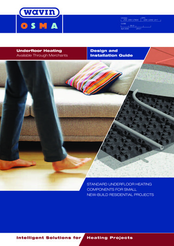
·Figure 4: Metal Roof AttachmentFigure 3: Shake and Shingle Roof le/roofedgeNone24”18”2.0 ft12”24”18”2.8 ft24”24”30”3.8 ft36”24”42”4.8 ftTable 7: Tracing Heights for Shake and Shingle RoofThe last column gives the amount of cable required per foot ofroof edge for standard shake and shingle roof (table 7) or ametal seam roof (table edgeNone18”18”2.5 ft12”18”24”2.8 ft24”18”36”3.6 ft36”18”48”4.3 ftNone24”18”2.0 ft12”24”24”2.4 ft24”24”36”2.9 ft36”24”48”3.6 ftTable 8:Tracing Heights for Metal Seam RoofHeating Cable InstallationPREPARE FOR INSTALLATIONSTEP1: CUT THE HEATING CABLE TO LENGTH1. Store the heating cable in a clean, dry place.1. Cut the heating cable to length required. This can be donebefore or after it is installed. Leave a minimum of 1 foot extraheating cable for power connection. For splice connectionsleave a minimum of 2 ft, and 3 ft for each tee connection.2. Inspect for any mechanical damage prior to installation.3. Warranty is void if non-King accessories are used. Kingapproved accessories include:- SRK00 Power connection kit- SRK03 Fiberglass tape and labels- SRK08 GFEP plug-in connection kit- SRK10 Splice and tee kit- SRK12 End seal kit-SRK13 Roof clips- SRK15 Downspout hanger bracketSTEP 2: ATTACH THE HEATING CABLE ON ROOFS1. Loosely loop the heating cable on the roof at the overhangarea. Pull the bottom of each heating cable loop over the roofedge and, using a UV-resistant cable tie as. Connect thebottom of each loop to the cable running in the gutter. This willensure a drainage channel for the melting ice to drain off theroof and into the gutter and downspout. The cable in the guttershould remain against the bottom of the gutter as shown inFigure 3 (Standard Roof) and Figure 4 (Metal Roof).4. Gutters and downspouts must be free of leaves and otherdebris.5. Carefully plan the routing of the heating cable for roof andgutter deicing.6. Inspected the mounting surface for sharp edges and removeas anything that could damage the cable.www.king-electric.com2. Extend the top of each heating cable loop beyond where thewall joins the roof.3. Use SRK13 roof clips to route heating cable up and down theedge of the roof according to the tracing height noted in thetables above and shown in Figures 6 and 7. Route the heatingcable in such a way as to prevent abrasion to the cable jacket.Rev 11.04.128
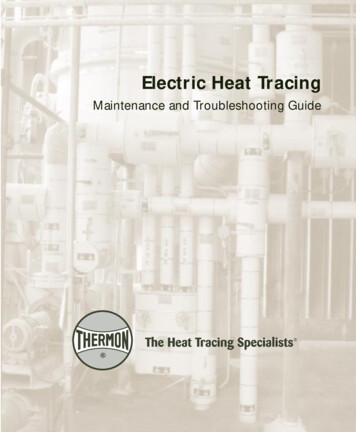
Figure 5: Roof Clip, Standard Shake RoofFigure 6: Roof Clip, Metal RoofSTEP 2 (continued)4. One SRK13 kit contains 25 roof clips for approximately 17linear feet of the roof edge.5. Roof clips may be attached to a shake or shingle roofusing nails or screws. Roof clips may be attached to ametal roof using nails, screws, or adhesive. Reseal thenail or screw holes if necessary before installing heatingcable in the clips. See SRK13 installation instructions foradditional details on mounting roof clips.6. A barrier (snow fence) can be placed on the roof abovethe heating cable. This prevents damage to the cable andkeeps the roof brackets from tearing loose during iceslides. The heating cable can be attached to the barrierwith UV-resistant cable ties, instead of using roof clips.The use of other materials, such as wire, may causedamage to the heating cable and will void the warranty.STEP 3: ATTACH THE HEATING CABLE ON VALLEYS1. Trace two-thirds of the way up each valley with a doublerun of heating cable as shown in Figure 7.Figure 7: Roof ValleysSTEP 4: INSTALLING THE CABLE IN GUTTERS ANDDOWNSPOUTS1. Run the heating cable in the gutters and into downspouts,end the cable in a loop at the bottom of the downspout andthen run the cable back up the downspout using a tiewraps to fasten it as shown in Figure 8. Permanentattachment of the cable to the gutter bottom is notnecessary.2. Use the King SRK15 downspout brackets at the transitionof the gutter and downspout to protect the cable fromfraying. Refer to the SRK15 installation instructions formore details.3. Route and secure cable with care to avoid mechanicaldamage during installation or maintenance from suchthings as ladders, etc.Figure 8: SRK15 Downspout Bracketwww.king-electric.comRev 11.04.129
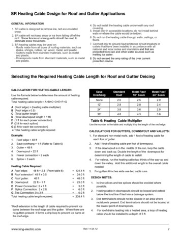
STEP 5: TERMINATING DOWNSPOUTS1.The preferred method of installation is to run the heatingcable into the downspouts, ending the cable in a loop atthe bottom of the downspout and then run the cableback up the downspout into the gutter . This way there isno end seal in the downspout. For single cable runs indownspouts with an end seal use a tie wrap to fasten itas shown in Figure 9. Do not leave the end of theheating cable pointing down at the end of thedownspout, double back as shown. Never create asituation where an end seal is positioned to be a drippoint at the end of a cable run.STEP 6: INSTALL END SEALS, SPLICES, TEES, ANDPOWER CONNECTION KITS1. If installing a GFEP device on the cable the carefully followthe SRK08 installation instructions.2. Use only listed weatherproof junction boxes approved forwet location when installing SR cable.3. ·Use only listed watertight construction or enclosures,Type 3, 3s 4, 4X ,6,or 6P.4. ·When possible, all power connection boxes should belocated in a protected area (such as under eaves) andentry should be at the bottom of the box. In all case, a driploop should be installed, do not let an end seal or splice ortee connection become a drip point.STEP 7: ATTACH THE WARNING LABLES1. Two warning labels are provided with the SR cable kit toindicate the presence of electric deicing and snow-meltingequipment on the premises. One label should be attachedat the electrical outlet cover and the other label must beposted at the fuse or circuit breaker panel feeding theoutlet circuit. Labels must be clearly visible.STEP 8: CHECK AND INSPECT THE INSTALLATION1. Prior to powering the deicing cable into the outlet, checkthe entire length of the cable for mechanical damage suchas nicks and cuts in the outer insulation and any potentialthermal damaged which may have occurred if cable wasexposed to excessive heat.2. Use a megohmmeter to test each circuit according to theinstructions in the “Heating Cable Testing andMaintenance” section of these instructions.Figure 9: Downspout TerminationGROUND FAULT PROTECTIONNational electrical codes require ground-fault equipmentprotection on each heating cable branch circuit. To reducethe risk of fire caused by damage or improper installation,circuit breakers with a 30-mA trip level are required.Alternative designs providing comparable levels of groundfault protection may also be acceptable.HEATING CABLE TESTING AND MAINTENANCE1.Make sure that gutter and downspouts are free of leavesand other debris annually prior to the winter season.2. Using a 2500-Vdc megohmmeter, check the resistancebetween both of the power prongs on the plug and theground prong after installing the heating cable. Minimumreading should be 1000 megohms.3. Record the original values for each circuit, and comparesubsequent readings taken during regular maintenanceto the original values.4. If the readings fall below 1000 megohms, replace thecable with a new unit. Do not attempt to repair the cable.5. Caution:·Maintenance and repair of the heating cablesystem should only be preformed by a qualified electrician.3. Junction boxes should be inspected for water and forevidence of water damage. If moisture is present, the boxshould be restored to a dry condition and the cause of thewater intrusion should be investigated and eliminated.4. Test the ground fault circuit to be sure it is functioningproperly. If malfunctioning, replace prior to energizing thesystem. Functionality of over-current protection devicessuch as circuit breakers or fuses should be checked aswell.WARNINGFire and shock hazard. Damaged heating cable cancause electrical shock, arcing, and fire. Do not attemptto repair or energize damaged heating cable.Ifdamaged, immediately repair or it and replace with anew ev 11.04.1210
Circuit Breaker Protection and Cable Length Design for DeicingTable 9: Circuit Breaker Protection for 2410Volts120V240V120V240V120V240V120V240VTable 10: Technical Data RatingsStart upTemp15 Amp(ft.)20 Amp(ft.)30 Amp(ft.)40 Amp(ft.)32ºF (0ºC)273273273273Maximum operating temp.150 F (65 C)20ºF (-7ºC)254268273273Maximum exposure temp.185 F (85 C)0ºF (-18ºC)213255273273Minimum installation temp.0 F (-18 C)-20ºF (-29ºC)182248273273Minimum bending radius1”, (24 mm)32ºF (0ºC)54754754754720ºF (-7ºC)5015475475470ºF (-18ºC)426547547547-20ºF (-29ºC)36849254754732ºF (0ºC)18821621621620ºF (-7ºC)1662162162160ºF (-18ºC)144193216216Technical Data Table.496” x .236”Dimensions(12.6mm x 6mm)110-120V,208V-277VService voltageTable 11: Maximum Single Run LengthModelVoltsOutput at32ºF (0ºC)MaximumSingle RunLengthSR123120V5.0 w/ft273 ft. (83M)208V4.1 w/ft530 ft. (129M)240V5.0 w/ft547 ft. (161M)277V5.9 w/ft590 ft. (180M)120V8.0 w/ft216 ft. (66M)208V7.1 w/ft397 ft. (121M)240V8.0 w/ft432 ft. (132M)277V9.0 w/ft466 ft. (142M)120V12.1 w/ft171 ft. (52M)208V11.4 w/ft312 ft. (95M)240V12.1 w/ft347 ft. (106M)277V13.0 w/ft385 ft. (117M)120V14.8 w/ft152 ft. (46M)208V14.2 w/ft274 ft. (83M)240V14.8 w/ft312 ft. (95M)277V15.8 w/ft346 ft. (106M)-20ºF (-29ºC)12717321621632ºF (0ºC)38143243243220ºF (-7ºC)3314324324320ºF (-18ºC)292387432432-20ºF (-29ºC)25834743243232ºF (0ºC)12616817117120ºF (-7ºC)1181571711710ºF (-18ºC)103136171171-20ºF (-29ºC)9212316817132ºF (0ºC)25734234734720ºF (-7ºC)2353113473470ºF (-18ºC)204268347347-20ºF (-29ºC)18424434734732ºF (0ºC)10214315215220ºF (-7ºC)971261521520ºF (-18ºC)88117152152-20ºF (-29ºC)7610415215232ºF (0ºC)17222631231220ºF (-7ºC)1592153123120ºF (-18ºC)150197298312Model208V277V-20ºF 1210SR2410Table 12: Circuit Length AdjustmentsTechnical Data Notes:1. The maximum single cable run is the longest length of heating cable before there is asignificant voltage drop which will lower the wattage rating of the cable.2. The circuit breaker sizes in Table 9 are per the National Electric Code (NEC).3. The NEC requires ground-fault equipment protection (GFEP) for fixed outdoor deicingequipment. All electrical connections should be made by a licensed electrician.www.king-electric.comRev 11.04.12Circuit length adjustments for 240Vcables operated 208V and 277V arenoted in table 12.11
1Open sealing fitting and slide the junction box sealingfittings onto the end of the cable as shown above.23Cut the braid and push it back to loosen it as shown.Bend the cable and gently pull it through the braid.45Notch the conductive core at the end and twist it backto peel the bus wires from the core.6www.king-electric.comRev 11.04.12Lightly score completely around and then downouter jacket a distance of 7”. Do not cut braid or innerjacket. Bend heating cable to break jacket at score,then peel off outer jacket!.Twist and position the braid to one side of heatingcable and then cut the insulating jacket back 6”.Lightly score the inner insulating jacket and thenbend the cable to break the jacket and peel it off.Score between the bus wires and bend the core tobreak it free and peel the core material away from thebus wires.12
7Slide the black 5 1/2” x 1/8” heat shrink tubes over thebus wires and apply heat.9Place the 1/2” x 1” heat shrink tube over the cable asshown.10Immediately pinch the tube with pliers between thebus wires while it is still hot and hold for 10 secondswww.king-electric.com81011Rev 11.04.12Slide the green/yellow 5 1/2” x 1/8” heat shrink tube overthe grounding braid and apply heat.Make sure the heat tube overlaps the outer jacketby ½” as shown and then apply heat to shrink the.Slide the sealing fitting parts to the end of the cableas shown13
11Insert fitting with sealing gasket and threaduntil snug. If junction box has clearance holethen thread locking nut down until snug.13Use wire nuts and make connections betweensupply wires and heating cable wires, inaddition to the ground wires. Not intended foruse with aluminum wire.ELECTRICAL CODESArticle 426 of the National Electrical Code (NEC), and Part1, Section 62 of the Canadian Electrical Code (CEC),govern the installation of SRP heating cables for roof andgutter deicing and must be followed.www.king-electric.com12Insert cable and tighten fitting.13Apply warning label.IMPORTANT: For the warranty to be valid, the installer,customer and user must comply with all the requirementsoutlined in these guidelines. All design informationprovided in these instructions are based on a “standard”shake or shingle and metal roof applications. For any otherapplication or method of installation, consult a designspecialist.Rev 11.04.1214
SRK12 End Seal KitInstallation, Operation and Maintenance InstructionsIMPORTANT: Save These Instructions!DESCRIPTION:SR self-regulating heating cables are designed fora variety of pipe freeze protection as well as roofand gutter deicing applications. The heat output(wattage) increases and decreases based on thetemperature, so the cable adjusts automatically tovarying climate conditions. This unique featureensures maximum energy efficiency by increasingthe heat output only when it is needed. Nothermostat is required.WARNING: ELECTRIC SHOCK HAZARDDisconnect all power before installing or servicingthe heating cable and accessories. SR heatingcable must be grounded properly in accordancewith the National Electrical Code (NEC). Failure tocomply can result in personal injury or propertydamage. Only a qualified licensed electricalcontractor shall install and service of SR heatingcable and accessories, otherwise the warranty isvoided.ItemQtyA1Black heat shrink tube (3/4” dia. x 5” length)B1Woven braid sleeve ( ½” dia. x 4” length)C1Black heat shrink cap ( ½” dia. x 1-1/4” length)1DescriptionScore the outer jacket 2” from the endof the cable.2Remove the outer jacket to exposethe braid.CAUTION: When removing the outerjacket, be careful not to damage the braidor the inner core insulation.www.king-electric.comNote:·All electrical wiring, including Ground FaultCircuit Interrupters (GFCI), must be done accordingto the NEC and local codes by a qualified installer.Article 426 of ANSI/NFPA 70 of National ElectricalCode (NEC section 62 of CAN/CSA-C22.1,Canadian Electrical Code, Part I(CEC) governs theinstallation of this heat systems3Push the braid back off the end of thecable.WARNING: ELECTRIC SHOCK HAZARDDo not connect the bus wires together.Keep braid out of heat shrink cap.Rev 11.04.1215
4Push back the braid and cut 3/4” offthe end of the cable.5Push back the braid and slide the heatshrink cap over the end of the cable.7Pull the braid back over the end cap andtwist the braid end together.8Slide the 4” woven braid sleeveover the cable, allowing 1/2” toextend past the end.10Apply heat evenly to the heat shrinktube unit it shrinks around the cable11While the shrink tubing is still hot,gently squeeze the end with pliersand hold it until it has cooled.6912Apply heat evenly until the cap shrinksaround the cable.Slide the 5” heat shrink tube over thewoven braid, allowing it to extend 1/2”past the end of the woven sleeve justapplied.The end must remain sealed afterthe pliers are removed. If the tubedoes not remain sealed, then repeatsteps 7 and 8.Warranty Information:King Electrical Mfg. Company will repair or replace, without charge to the original owner, any heating cable found to be defective or malfunctioning within the 2 year warranty.In Case of Product Failure: Contact King Electrical Mfg. Co. at 800.603.5464. The owner will be required to provide, within the designated warranty period, the followinginformation: model number, date of purchase, and a complete description of the problem encountered with product. Upon receipt of the aforementioned, the company willreply to the owner within a period not to exceed fifteen (15) working days, and will provide the action to be taken by owner. Terms: This warranty requires the owner or hisagent install the equipment in accordance with the National Electrical Code, any other applicable heating or electrical codes and the manufacturer's installation instructions. Itfurther requires that reasonable and necessary maintenance be performed on the unit. Failure of proper maintenance by owner will void the warranty in its entirety. Thecompany is not liable for any actions it deems to be abuse or misuse of the product. The customer shall be responsible for all costs incurred in the removal or reinstallation ofproducts, including, but not limited to, labor costs, and shipping costs incurred to return products to King Manufacturing. At their discretion, King Manufacturing will decide toeither repair or replace the product, with no charge to the owner, with return freight paid by King. The Company shall not be liable for consequential damages arising withrespect to the product, whether based upon negligence, tort, strict liability or contract. No other written or oral warranty applies, nor any warranties by Representatives,Dealers, Employees of King or any other person. King Manufacturing can be contacted by phone at 206.762.0400, fax 206.763.7738 or website www.king‐electric.com.Thecompany's minimum liability shall not in any case exceed the list price for the product claimed to be defective.www.king-electric.comRev 11.04.1216
dams between the roof edge and the gutter. When there are no gutters present it forms a drip loop to prevent ice dams at the roof edge. 4. Do not install the heating cable underneath any roof covering. 5. Install only in accessible locations; do not install behind walls or where the cable would be hidden. 6.