Transcription
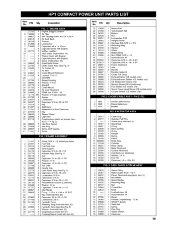
HP1 COMPACT POWER UNIT PARTS LISTItemP/NNoQtyDescriptionFIG. 1 - ENGINE 12988238466----4237721----1----1----1----208668 8407752123812103906212175 e, Briggs & StrattonOil FilterSelf Tapping Screw, #10-24 x 3/8 in.Air Duct, BackWasherLockwasherCapscrew, M6 x 1 x 16 mmCapscrew (Incld with Engine)Muffler, modifiedHeat Shield (incld w/item 14)Washer (Incld with Engine)Capscrew (Incld with Engine)Screw (incld w/item 14)Sheet Metal ScrewChoke Cable Assy (See Fig. 3)Oil Cooler KitNo ItemCooler Mount WeldmentLocknut, 7/16-14NO ITEMBlower HousingWasher, 7/16 in.StandoffCooler MountAir Duct WeldmentESNA Nut, 5/16 in. -18Washer, 5/16 (as required)SpacerLockwasherCapscrew, 5/16 in.-18 x 2-1/2KeySet ScrewBlower Hub & Shaft ExtensionKeyBlower WheelCapscrewCoupling Assy (incld set screws, item30 & 31 in fig. 2)Inlet Ring GasketInlet RingScrew, Self TappingScrewFIG. 2 FRAME , 5/16 in.-18, slotted pan headFuel TankFuel Tank CapTank SupportCapscrew, 5/16 in.-18 x 1/2Actuator Assy (See Fig. 4)NutCapscrew, 1/4 in.-20 x 1-1/4Washer, 1/4 in.Capscrew, 1/4 in.-20 x 1-1/2Top GrilleHandle GripDash Panel Assy (See Fig. 5)Capscrew, 5/16 in.-18 x 3/4Lockwasher, 5/16 in.Flatwasher, 5/16 in.Capscrew, 5/16 in.-18 x 1-1/2Proposition 65 Sticker (California)Washer, 1/4 in.Capscrew, 7/16 in.-14 x 1-1/2Inlet FlangeO-ring, 1-1/2 in. x 1-3/4 x 1/8 R17Key (Incld with item 26)Capscrew, 3/8 in.-16 x 1-1/4Lockwasher, 3/8 in.Hydraulic PumpRetaining Ring (Incld with item 30)Hydraulic Tank Assy (See Fig. 6)Washer, (Incld with item 30)Coupling Assy (Incld item 31)Coupling Sleeve (Incld with item 30)ItemP/NNoQty32 1049933 0775834 0430335 0042936 0303137 2898338 0522739 3124040 0191841 1631042 0456643 0390644----45 37050446 37051347 2809148 1636349 2809350 5668751 0776452 2898553 2898854 2832355 2878856 2898457 2903658 28786111221222214224122111111111DescriptionBattery PadTank Support TabBatteryNutLockwasher, 5/16Weight StickerCarriage Bolt, 5/16 in. x 3/4Retaining RingWasherWheelBattery StrapNut, ESNA, 5/16 in.-18Incld with item 47Capscrew, 5/16 in.-18 x 2-3/4Capscrew, 5/16 in.-18 x 1-3/4Frame WeldmentAxleHandleThrottle Cable KitChoke Pull DecalExhaust Sticker (CE models only)Exhaust Fumes Sticker (CE models only)CE Sticker (CE models only)Manual Sticker (CE models only)Fuel Sticker (CE models only)Sound Power Level Sticker (CE models only)Coupler Sticker (CE models only)FIG.3 CHOKE CABLE ASSY - P/N 23722123NSSNSSNSS111Choke Cable AnchorChoke Cable AssyBracketFIG. 4 ACTUATOR ASSY1 049132 237173----4 151615 068916 028387 233708 151609 2055010 1514811 36000912 1515813 0593114 2378515 2378416 2378317 0453918 1516219 007691111121111111111111Cable StopCylinder Pull WireScrew (incld with item 1)Gland CapO-ringBack-up RingO-ringKeeperSpringPistonHose AssyCylinderHose ClampBase WeldmentControl WeldmentCylinder Lever WeldmentWasher, 1/4 in.Fast PinCapscrew, 1/4 in.-20 x 3/4FIG. 5 DASH PANEL & VALVE l FittingMale Coupler Body - 1/2 in.Panel Weldment Assy (incld item 12)Hour MeterSpool WasherRetaining RingNutControl RodKnobIncld with item 14Incld with item 14DecalFemale Coupler Body - 1/2 in.ON/OFF SwitchSteel BallSpringPipe PlugStarter SwitchCapscrew19
ItemNoP/NQtyDescriptionFIG. 5 DASH PANEL & VALVE ASSY Continued . . 5504868------------00140211211111111111211Lock WasherElbow FittingElbow FittingDowel PinCapscrewLock WasherBarValve SpoolBackup RingO-ringValve BlockRelief ValvePipe PlugElbow Hose BarbIncld with item 4Incld with item 4Incld with item 4Quad RingFIG. 6 TANK 1114111111111Filler CapCapscrew, 5/16 in.-18 x 1-1/2Hydraulic Oil StickerFiller TopO-ringOil Filter (Baldwin PT-289)SpringO-ringHydraulic Filter Enclosure45 Degree ElbowHose End BarbCapscrew, 1/4 in.-20 x 1-1/2Filter BlockSteel BallSpringPipe PlugGasketFilter Grip PlateBreatherSight PipeHydraulic TankFIG. 7 HOSES, FITTINGS, and 199473124326111121211111111190 Degree ElbowHose ClampHoseHose AssyHose AssyHoseHose ClampSuction HoseHose ClampSuction SleeveSuction TubeHoseElbow FittingWire Tie (as required)Hose ClampFuel HoseFuel Filter & Hose AssyWire TieIAGRAMItemP/NNo1 3720672 237153 091534 163205 236856 163217 087208 288989----10 2368111 2368412 0872413 23682Qty3111111111111DescriptionDouble Spade ConnectorDiode Wire AssyWire Assy (14 gauge, black)Wire Assy (14 gauge, red)Wire Assy (14 gauge, yellow)Wire Assy (14 gauge, white)Wire Assy (6 gauge, black)Wire Assy (6 gauge, red)Wire, 14 gauge, red, incld w/engineWire Assy (14 gauge, green)Wire Assy (14 gauge, black)Wire Assy (14 gauge, black)Wire Assy (14 gauge, green)NOTE: Use Figure Number and ItemNumber when ordering.MODEL DESCRIPTIONSHP18294HP1829401HP18299Compact Power Unit - U.S.A.Compact Power Unit - CE (European Communities)Compact Power Unit with HoseBasket - U.S.A.NOTES
21June 1997
22June 1997
June 1997June 199723
24June 1997
June 199725
Figure 6AHydraulic Tank Parts05/22/02P/N 35277204306111111111DESCRIPTIONHydraulic Tank Kit(Incld items 1-14)LidSpringService Kit (Incld Item4), Lid O-ring, FilterReceptacle O-ring,Breather Element andBreather Cover)Filter ElementFilter Assy (IncldItems 1-5 and 11-13)CapscrewElbow, 45 CapscrewTankGrip PlateGasketDipstick BoltDipstickHoseFilter Bowl P/N58487Breather BoltAssemblyP/N 58488Plastic WasherP/N 58489Plastic WasherP/N 58489ClampP/N 0488925P/N 01258O-RingFilter HeadP/N 58486
26June 1997
1213111GREENBLACKBLACKTOGGLESWITCHHOUR METERWHITE2YELLOW1BROWNGREENSTARTSWITCH10OIL ER65TO ENGINEKILL SWITCHTO FUELSHUT-OFF SWITCHFigure 8. Wiring DiagramSept 199827
P/N 29361 WATER PUMP KIT (Optional Accessory)DO NOT OPERATE THE PUMP WITHOUT WATER. OPERATING THE PUMPWITHOUT WATER WILL SEVERLY DAMAGE THE criptionPump BracketAdapterStub ShaftFaspinCapscrewSetscrewDrive CouplingWater PumpCapscrewESNA 111321ItemNo.DescriptionHex Sem ScrewRotating ScreenHex ScrewScreen SpacerChainMesh Filter WasherGarden Hose Conn.NipplePipe TeeHose 1111114Regulator AssyHoseHose ClampHose BarbCaution StickerCable TieAdapterInstuction SheetKeyWasherP/N 13360 HOSE BASKET KIT (Optional 143DescriptionHose Basket AssyCapscrewNut
WARRANTYStanley Hydraulic Tools (hereinafter called “Stanley”), subject to the exceptions contained below, warrants new hydraulic tools for a period of one yearfrom the date of sale to the first retail purchaser, or for a period of 2 years from the shipping date from Stanley, whichever period expires first, to be freeof defects in material and/or workmanship at the time of delivery, and will, at its option, repair or replace any tool or part of a tool, or new part, which isfound upon examination by a Stanley authorized service outlet or by Stanley’s factory in Milwaukie, Oregon to be DEFECTIVE IN MATERIAL AND/ORWORKMANSHIP.EXCEPTIONS FROM WARRANTYNEW PARTS: New parts which are obtained individually are warranted, subject to the exceptions herein, to be free of defects in material and/orworkmanship at the time of delivery and for a period of 6 months after the date of first usage. Seals and diaphragms are warranted to be free of defectsin material and/or workmanship at the time of delivery and for a period of 6 months after the date of first usage or 2 years after the date of delivery,whichever period expires first. Warranty for new parts is limited to replacement of defective parts only. Labor is not covered.FREIGHT COSTS: Freight costs to return parts to Stanley, if requested by Stanley for the purpose of evaluating a warranty claim for warranty credit, arecovered under this policy if the claimed part or parts are approved for warranty credit. Freight costs for any part or parts which are not approved forwarranty credit will be the responsibility of the individual.SEALS & DIAPHRAGMS: Seals and diaphragms installed in new tools are warranted to be free of defects in material and/or workmanship for a periodof 6 months after the date of first usage, or for a period of 2 years from the shipping date from Stanley, whichever period expires first.CUTTING ACCESSORIES: Cutting accessories such as breaker tool bits are warranted to be free of defects in material and or workmanship at thetime of delivery only.ITEMS PRODUCED BY OTHER MANUFACTURERS: Components which are not manufactured by Stanley and are warranted by their respectivemanufacturers.a. Costs incurred to remove a Stanley manufactured component in order to service an item manufactured by othermanufacturers.ALTERATIONS & MODIFICATIONS: Alterations or modifications to any tool or part. All obligations under this warranty shall be terminated if the newtool or part is altered or modified in any way.NORMAL WEAR: any failure or performance deficiency attributable to normal wear and tear such as tool bushings, retaining pins, wear plates,bumpers, retaining rings and plugs, rubber bushings, recoil springs, etc.INCIDENTAL/CONSEQUENTIAL DAMAGES: To the fullest extent permitted by applicable law, in no event will STANLEY be liable for any incidental,consequential or special damages and/or expenses.FREIGHT DAMAGE: Damage caused by improper storage or freight handling.LOSS TIME: Loss of operating time to the user while the tool(s) is out of service.IMPROPER OPERATION: Any failure or performance deficiency attributable to a failure to follow the guidelines and/or procedures as outlined in thetool’s operation and maintenance manual.MAINTENANCE: Any failure or performance deficiency attributable to not maintaining the tool(s) in good operating condition as outlined in theOperation and Maintenance Manual.HYDRAULIC PRESSURE & FLOW, HEAT, TYPE OF FLUID: Any failure or performance deficiency attributable to excess hydraulic pressure, excesshydraulic back-pressure, excess hydraulic flow, excessive heat, or incorrect hydraulic fluid.REPAIRS OR ALTERATIONS: Any failure or performance deficiency attributable to repairs by anyone which in Stanley’s sole judgement caused orcontributed to the failure or deficiency.MIS-APPLICATION: Any failure or performance deficiency attributable to mis-application. “Mis-application” is defined as usage of products for whichthey were not originally intended or usage of products in such a matter which exposes them to abuse or accident, without first obtaining the writtenconsent of Stanley. PERMISSION TO APPLY ANY PRODUCT FOR WHICH IT WAS NOT ORIGINALLY INTENDED CAN ONLY BE OBTAINED FROMSTANLEY ENGINEERING.WARRANTY REGISTRATION: STANLEY ASSUMES NO LIABILITY FOR WARRANTY CLAIMS SUBMITTED FOR WHICH NO TOOL REGISTRATION IS ON RECORD. In the event a warranty claim is submitted and no tool registration is on record, no warranty credit will be issued without firstreceiving documentation which proves the sale of the tool or the tools’ first date of usage. The term “DOCUMENTATION” as used in this paragraph isdefined as a bill of sale, or letter of intent from the first retail customer. A WARRANTY REGISTRATION FORM THAT IS NOT ALSO ON RECORDWITH STANLEY WILL NOT BE ACCEPTED AS “DOCUMENTATION”.NO ADDITIONAL WARRANTIES OR REPRESENTATIONSThis limited warranty and the obligation of Stanley thereunder is in lieu of all other warranties, expressed or implied including merchantability or fitnessfor a particular purpose except for that provided herein. There is no other warranty. This warranty gives the purchaser specific legal rights andother rights may be available which might vary depending upon applicable law.29
SALES & SERVICE DIRECTORYNORTH AMERICA &CORPORATEHEADQUARTERSStanley Hydraulic Tools3810 S.E. Naef RoadMilwaukie, Oregon U.S.A. 97267-5698Tel: 503 659 5660Fax: 503 652 1780EUROPEAN HEADQUARTERSStanley Hydraulic Tools3810 S.E. Naef RoadMilwaukie, Oregon U.S.A. 97267-5698Tel: 503 659 5660Fax: 503 652 1780NORTHERN EUROPEStanley Svenska AbBox 1054Datavagen 51S436 22 Askim, SwedenTel: 46 31 289775Fax: 46 31 288099SOUTHERN EUROPEStanley Tools S.p.A.Via Trieste 122060 Figino Serenza (Co.)ItalyTel: 39 31 785111Fax: 39 31 781766 / 781094CENTRAL & SOUTHAMERICA HEADQUARTERSStanley Hydraulic Tools3810 S.E. Naef RoadMilwaukie, Oregon U.S.A. 97267-5698Tel: 503 659 5660Fax: 503 652 1780ASIA PACIFICHEADQUARTERSStanley Hydraulic Tools AsiaNo. 25 Senoke SouthWoodland East Industrial EstateJurong TownSingapore 2775Tel: 65 7522001Fax: 65 7522018Telex: RS 23945 STANLEYAUSTRALIA-NEW ZEALANDHEADQUARTERSStanley Hydraulic Tools3810 S.E. Naef RoadMilwaukie, Oregon U.S.A. 97267-5698Tel: 503 659 5660Fax: 503 652 1780Stanley Hydraulic ToolsDivision of the Stanley Works3810 S.E. Naef RoadMilwaukie, Oregon 97267-5698Phone: 503/659-5660Fax: 503/652-1780
26 04134 1 Hydraulic Pump 27 ----- 1 Retaining Ring (Incld with item 30) 28 07803 1 Hydraulic Tank Assy (See Fig. 6) . Stanley Hydraulic Tools (hereinafter called "Stanley"), subject to the exceptions contained below, warrants new hydraulic tools for a period of one year