Transcription
Lecture NotesElements of Electrical MachinesVEER SURENDRA SAI UNIVERSITY OF TECHNOLOGY BURLA, ODISHA, INDIADEPARTMENT OF ELECTRICAL ENGINEERINGElements of Electrical MachinesLecture NotesSubject Code: BEE 1301For 3rd Semester Mechanical Engineering and Production Engineering students1
Lecture NotesElements of Electrical MachinesDisclaimerThis document does not claim any originality and cannot be used as a substitute for prescribedtextbooks. The information presented here is merely a collection by the committee members for theirrespective teaching assignments. Various sources as mentioned at the reference of the document aswell as freely available material from internet were consulted for preparing this document. Theownership of the information lies with the respective authors or institutions. Further, this document isnot intended to be used for commercial purpose and the committee members are not accountable forany issues, legal or otherwise, arising out of use of this document. The committee members make norepresentations or warranties with respect to the accuracy or completeness of the contents of thisdocument and specifically disclaim any implied warranties of merchantability or fitness for a particularpurpose. The committee members shall be liable for any loss of profit or any other commercialdamages, including but not limited to special, incidental, consequential, or other damages.2
Lecture NotesElements of Electrical MachinesVeer Surendra Sai University of Technology, Odisha, Burla, IndiaDepartment of Electrical Engineering,(3RD SEMESTER)ELEMENTS OF ELECTRICAL MACHINES (3-1-0)(For Mechanical and Production Engineering Students)ModuleChapterLecture no.TopicsD.C. Generator1Construction and principle of operation2E.M.F. equation, types of generator3No load and load characteristics, Voltage build-up ofModule Ishunt Generator4Voltage regulation, Application5Back E.M.F, torque and speed equations6Speed control of series and shunt motors7Characteristics and performance curves8Motor starters9 & 10Losses and Efficiency of D.C machinesSingle phase11Construction and principle of operationTransformer12E.M.F. equation13Phasor diagram14Actual and approximate equivalent circuits15Open and short circuit tests, voltage regulation16Losses and efficiencyThree Phase17Construction and principle of operationTransformer18Connection of three single –phase units in wye, delta,D.C. MotorModule IIopen delta configurations19Autotransformer; conventional transformer connected asAutotransformer20Special Transformers – induction heating and highimpedance and high frequency transformerThree- phase21construction and principle of operation3
Lecture NotesElements of Electrical MachinesModule IIIalternators22E.M.F. equation, distribution and pitch factors23Synchronous reactance24performance of alternators on no-load and load; Phasordiagram; voltage regulationModule IV25power calculations of turbine and hydro-generators26synchronization of an alternatorThree-Phase27Construction and principle operationSynchronous28 & 29Complete phasor diagrams, V- curvesMotor30Starting methods of synchronous motor and applicationsThree-Phase31Construction of slip ring and squirrel cage typeinduction Motorinduction motors32Starting and running torque of a three phase inductionmotor33torque-slip characteristics; maximum torque calculations34speed control of induction motors35Open and short-circuit tests36losses and efficiency37starting of induction motorsSingle-Phase38Construction and principle of operationInduction Motor39Analysis of single phase motor based on doublerevolving field theorem40Torque slip characteristic, capacitor- start and capacitorrun motorsREFERENCES[1] I. J. Nagrath & D.P. Kothari, “Theory and problems of Electrical Machines”, TMH Publication, NewDelhi.[2] B.L.Theraja & A.K.Theraja, “A Text Book of Electrical Technology”, Volume II, S. Chand &Company Ltd.[3] P. S. Bhimbra, “Electrical Machinary”, Khanna Publishers, New Delhi.[4] NPTEL course materials.[5] http://electrical4u.com/, Electrical4u, online Electrical Engineering study site, accessed on January2015.4
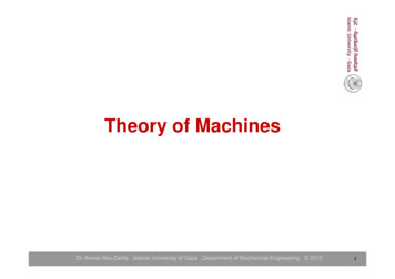
Lecture NotesElements of Electrical MachinesD.C GeneratorAn electrical Generator is a machine which converts mechanical energy (or power) into electricalenergy (or power). The generator operates on the principle of the production of dynamically induced emfi.e., whenever flux is cut by the conductor, dynamically induced emf is produced in it according to thelaws of electromagnetic induction, which will cause a flow of current in the conductor if the circuit isclosed.Hence, the basic essential parts of an electric generator are:A magnetic field andA conductor or conductors which can so move as to cut the fluxIn dc generators the field is produced by the field magnets which are stationary. Permanentmagnets are used for very small capacity machines and electromagnets are used for large machines tocreate magnetic flux. The conductors are situated on the periphery of the armature being rotated by theprime-mover.Fig. 1.1 Basics of dc generators5
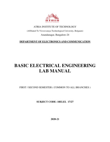
Lecture Notes1.1Elements of Electrical MachinesPractical DC generator constructionFig. 1.2 Cut-away view of dc practical generatorsThe actual DC generator consists of the following essential parts:a) Magnetic frame or Yoke Pole Cores and Pole Shoes Pole Coils or Field Coils Armature Core Armature Windings or Conductors Commutator Brushes and BearingsMagnetic frame or YokePurpose of Yoke is1. It act as a protecting cover for whole machine2. It provides mechanical support for poles6
Lecture NotesElements of Electrical Machines3. It carries the magnetic flux produced by polesb)Pole Cores and Pole ShoesThe field magnets consist of pole cores and pole shoes. The Pole shoes serve two purposes:1. They spread out the flux in the air gap2. They support the exciting coilsc)ArmatureWhen current is passed through field coils, they electro-magnetize the poles which producethe necessary flux.The Armature serves two purposes:1. Armature houses the armature conductors or coils2. It provides low reluctance path for fluxIt is drum shaped and is built up of laminations made sheet steel to reduce eddy current loss.Slots are punched on the outer periphery of the disc. The Armature windings or conductors arewound in the form of flat rectangular coils and are placed in the slots of the Armature. The Armaturewindings are insulated from the armature body by insulating materials.d)Commutator and brushesThe function of Commutator is to facilitate collection of current from the armatureconductors and converts the alternating current induced in the armature conductors intounidirectional current in the external load circuit. The commutator is made up of insulated coppersegments. Two brushes are pressed to the commutator to permit current flow. The Brushes are madeof carbon or Graphite. Bearings are used for smooth running of the machine.1.2E.M.F. equation7
Lecture NotesElements of Electrical MachinesLet, flux per pole in weberz total number of armature conductors no. of slots no. of conductors/slotP no. of generator polesA no. of parallel paths in armatureN armature rotation in revolutions per minute (rpm)E emf induced in any parallel path in armatureGenerated emf, E g emf generated in any one of the parallel path i.e. EAverage emf generated/conductor d volts, n 1dtNow, flux cut per conductor in one revolution,d P weberNo. of revolutions per second Time for one revolution, dt N6060secondNHence, according to Faradays laws of Electromagnetic induction,EMF generated/conductor d PNvolts dt60For a simplex lap-wound generator:No. of parallel paths PNo. of conductors in one path Hence, EMF generated/path zP PN60 z zNvolts P60For a simplex wave-wound generator:No. of parallel paths 28
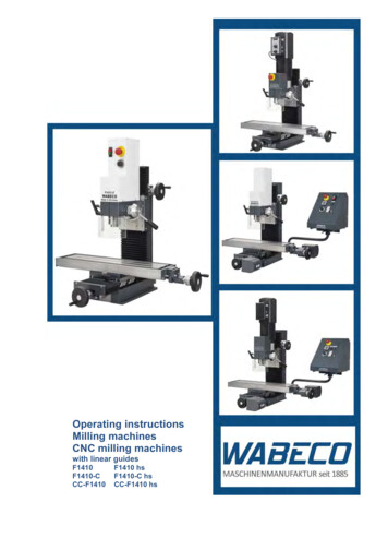
Lecture NotesElements of Electrical MachinesNo. of conductors in one path Hence, EMF generated/path z2 PN60In general generated EMF, E g 1.3 zN60z zNPvolts 2 120 PATypes of generatorDC generators are usually classified according to the way in which their fields are excited.DC generators may be divided into, (a) separately excited dc generators, and (b) self excited dcgenerators.a) separately excited dc generatorsSeparately excited generators are those whose field magnets are energized from anindependent external source of dc current.b) self excited dc generatorsSelf excited generators are those whose field magnets are energized by the current producedby the generators themselves. Due to residual magnetism, there is always present some flux in thepoles. When the armature is rotated, some emf and hence some current flows which is partly or fullypassed through the field coils thereby strengthening the residual pole flux.There are three types of self excited dc generators named according to the manner in whichtheir field coils (or windings) are connected to the armature. In shunt the two windings, field andarmature are in parallel while in series type the two windings are in series. In compound type thepart of the field winding is in parallel while other part in series with the armature winding.9
Lecture NotesElements of Electrical MachinesFig.1.3 DC generators classification10
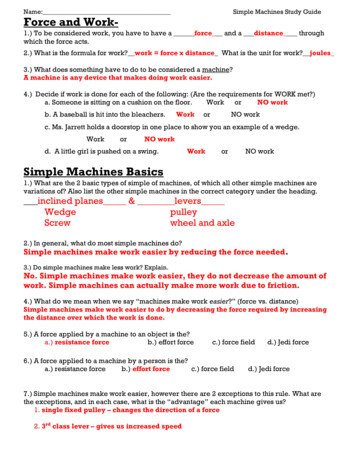
Lecture NotesElements of Electrical MachinesD.C. MotorAn electric motor is a machine which converts electrical energy into mechanical energy.2.1Principle of operationIt is based on the principle that when a current-carrying conductor is placed in a magnetic field, itexperiences a mechanical force whose direction is given by Fleming's Left-hand rule and whosemagnitude is given byForce, F B I l newtonWhere B is the magnetic field in weber/m2. I is the current in amperes and l is the length of the coil inmeter.Fleming’s left hand rule says that if we extend the index finger, middle finger and thumb of ourleft hand in such a way that the current carrying conductor is placed in a magnetic field (represented bythe index finger) is perpendicular to the direction of current (represented by the middle finger), then theconductor experiences a force in the direction (represented by the thumb) mutually perpendicular to boththe direction of field and the current in the conductor.Figure 2.1: Force in DC MotorFigure 2.2 : Magnetic Field in DC Motor11
Lecture NotesElements of Electrical MachinesFigure 2.3 : Torque in DC MotorFigure 2.4 : Current Flow in DC MotorConstructionally, there is no basic difference between a dc generator and motor. In fact, the samedc machine can be used interchangeably as a generator or as a motor. The basic construction of a dcmotor contains a current carrying armature which is connected to the supply end through commutatorsegments and brushes and placed within the north south poles of a permanent or an electro-magnet.Fig. 2.5 Flemings Left hand rule2.2Back E.M.FWhen the motor armature rotates, the conductors also rotate and hence cut the flux. In accordancewith the laws of electromagnetic induction, emf is induced in them whose direction, as found by12
Lecture NotesElements of Electrical MachinesFleming’s Right hand Rule, is in opposition to the applied voltage. Because of its opposing direction, it isreferred to as counter emf of back emf Eb . V has to drive I a against the opposition of Eb . The powerrequired to overcome this opposition is Eb I a .2.3Voltage Equation of a MotorThe voltage V applied across the motor armature has to,(a) Overcome the back emf Eb , and(b) Supply the armature ohmic drop I a RaHence, V Eb I a RaThis is known as voltage equation of a dc motor.Now, multiplying both sides by I a , we getVI a Eb I a I a2 RaWhere, VI a Electrical power input to the armatureEb I a Electrical equivalent of mechanical power developed in the armatureI a2 Ra copper loss in the armature2.4Condition for maximum efficiencyThe gross mechanical power developed by motor is, Pm VI a I a2 RaDifferentiating both side with respect to I a and equating the result to zero, we getdPm V 2 I a Ra 0dI aHence, I a Ra V / 2As, V Eb I a Ra and I a Ra V / 2Hence, Eb V / 213
Lecture NotesElements of Electrical MachinesThus gross mechanical power developed by a motor is maximum when back emf is equal to halfthe supply voltage. This condition is, however, not realized in practice, because in that case current wouldbe much beyond the normal current of the motor. Moreover, half the input would be wasted in the form ofheat and taking other losses (mechanical and magnetic) into consideration, the motor efficiency will bewell below 50 percent.2.5TorqueThe turning or twisting moment of a force about an axis is called torque. It is measured by theproduct of the force and the radius at which this force acts.Consider a pulley of radius r meter acted upon by a circumferential force of F newton whichcauses it to rotate at N rpm.Then torque T F r newton-metre(N-mWork done by this force in one revolution Force distance F 2 r joulePower developed F 2 r N joule/second or watt F r 2 N wattNow, 2 N angular velocity in radian per second and F r torque THence, power developed T watt or P T wattMoreover, if N is in rpm, then 2 N / 60 rad/sHence, P 2.5.12 N2 NT T or P .NT 60609.55Armature torque of a motorLet Ta be the torque developed by the armature of a motor running at N rps. If Ta is in N-m, thenpower developed Ta 2 N watt14
Lecture NotesElements of Electrical MachinesWe also know that electrical power converted into mechanical power in the armature Eb I awatt.Comparing above equations, we get Ta 2 N Eb I aAfter simplification, if N in rps, Ta If N is in rpm, then Ta 9.55Eb I a2 NEb I aN-mNAlso, Ta 0.159 ZI a P / A N-m2.5.2 Shaft torqueThe whole of the armature torque, as calculated above, is not available for doing useful work,because of iron and friction losses in the motor. The torque which is available for doing useful work isknown as shaft torque Tsh . The motor output is given byOutput Tsh 2 N watt provided Tsh is in N-m and N in rps.Hence, Tsh Output in watts, if N is in rps2 NAnd, if N is in rpm, then Tsh 2.6Output in wattsOutput 9.552 N / 60NSpeed Control of DC MotorSpeed control means intentional change of the drive speed to a value required for performing thespecific work process. Speed control is a different concept from speed regulation where there is naturalchange in speed due to change in load on the shaft. Speed control is either done manually by the operatoror by means of some automatic control device.One of the important features of dc motor is that its speed can be controlled with relative ease.We know that the expression of speed control dc motor is given as,15
Lecture NotesN Elements of Electrical MachinesV I a Ra A V I a Rarps. KZ P Where, Ra armature circuit resistance.Therefore speed (N ) of 3 types of dc motor – SERIES, SHUNT AND COMPOUND can becontrolled by changing the quantities on RHS of the expression. So speed can be varied by changing(i) terminal voltage of the armature V ,(ii) armature circuit resistance R and(iii) flux per pole .The first two cases involve change that affects armature circuit and the third one involves changein magnetic field. Therefore speed control of dc motor is classified as1) armature control methods and2) field control methods.2.7Motor startersThe starting of DC motor is somewhat different from the starting of all other types of electricalmotors. This difference is credited to the fact that a dc motor unlike other types of motor has a very highstarting current that has the potential of damaging the internal circuit of the armature winding of dcmotor if not restricted to some limited value. This limitation to the starting current of dc motor is broughtabout by means of the starter. Thus the distinguishing fact about the starting methods of dc motor is that itis facilitated by means of a starter. Or rather a device containing a variable resistance connected in seriesto the armature winding so as to limit the starting current of dc motor to a desired optimum value takinginto consideration the safety aspect of the motor.Starters can be of several types and requires a great deal of explanation and some intricate levelunderstanding. But on a brief over-view the main types of starters used in the industry today can beillustrated as:1. 3 point starter.16
Lecture NotesElements of Electrical Machines2. 4 point starter.Fig. 2.617
Lecture NotesElements of Electrical MachinesFig. 2.7Fig. 2.818
Lecture NotesElements of Electrical MachinesSingle phase Transformer3.1Principle of operation and constructionA transformer is a static or stationary piece of apparatus by means of which electric power in onecircuit is transformed into electric power of the same frequency in another circuit. Although transformershave no moving parts, they are essential to electromechanical energy conversion. They make it possible toincrease or decrease the voltage so that power can be transmitted at a voltage level that results in lowcosts, and can be distributed and used safely. In addition, they can provide matching of impedances, andregulate the flow of power (real or reactive) in a network. The physical basis of a transformer is mutual induction between two circuits linked by a commonmagnetic field. In its simplest form, it consists of two inductive coils which are electrically separated butmagnetically linked through a path of low reluctance. The two coils posses high mutualinductance. If one coil is connected to a source of alternating voltage, an alternating flux is set up in thelaminated core, most of which is linked with the other coil in which it produces mutually inducedemf.Constructionally, the transformers are of two general types, distinguished from each other merelyby the manner in which the primary and secondary coils are placed around the laminated core.a) Core typeb) Shell typeIn the so-called core type transformer, the windings surround a considerable part of the corewhereas in shell-type transformer, the core surrounds considerable portions of the winding.19
Lecture NotesElements of Electrical MachinesFig.3.1 Physical diagram of a transformer3.2Elementary theory of an ideal transformerAn ideal transformer is one which has no losses i.e. its windings have no ohmicresistance, there is no magnetic leakage and hence which has no copper and core losses. An idealtransformer consists of two purely inductive coils wound on a loss free core.In its simplest form it consist of, two inductive coils which are electrically separatedbut magnetically linked through a path of low reluctance. If one coil (primary) is connected to a source ofalternating voltage, an alternating flux is set up in the laminated core, most of which is linked with theother coil in which it produces mutually-induced e.m.f. according to Faraday's Laws of ElectromagneticInduction. If the second coil (secondary circuit) is closed, a current flows in it and so electric energy istransferred (entirely magnetically) from the first coil to the second coil.20
Lecture NotesElements of Electrical MachinesFig.3.2 Elementary TransformerFig.3.3 Vector representation of applied voltage, induced emf flux and magnetizing current of a singlephase transformer3.2E.M.F. equationLet, N 1 No. of turns in primaryN 2 No. of turns in secondary m Maximum flux in core in webers Bm ABm Maximum flux densityA Areaf Frequency of ac input in Hz21
Lecture NotesElements of Electrical MachinesThe flux increases from its zero value to maximum value m in one quarter of the cycle i.e. in1 / 4 f second.The average rate of change of flux m1/ 4 f 4 f m wb/sec or voltsNow, rate of change of flux per turn means induced emf in volts.Hence, average EMF/turn 4 f m voltsIf flux varies sinusoidally, then rms value of induced emf is obtained by multiplying the averagevalue with form factor.Form factor rms value of ac quantity 1.11average value of ac quantityHence, rms value of EMF/turn 1.11 4 f m 4.44 f m voltsNow, r.m.s value of induced e.m.f in the whole of primary winding (induced e.m.f. / turn) x No. of primary windingE1 4.44 f m N1 ------------------- ( i )Similarly, r.m.s. value of e.m.f. induced in secondary is,E2 4.44 f m N 2 ------------------- ( ii )Voltage transformation ratioE2 N 2 KE1 N1This constant K is known as voltage transformation ratio.(i)If K 1, then the transformer is called step-up transformer.(ii)If K 1, then the transformer is called step-down transformer.3.3Transformer with losses but no magnetic leakage22
Lecture NotesElements of Electrical MachinesThere are two cases, (i) when a transformer is on no load and (ii) when it is loaded.3.4Actual and approximate equivalent circuitsFig. 3.3(a)Fig. 3.3(b)23
Lecture NotesElements of Electrical MachinesFig.3.4 Approximate equivalent circuit of transformer3.5Open and short circuit testsFig.3.5 Circuit Diagram for No Load TestFig.3.6 (a) Equivalent Circuit on No LoadFig.3.7 (b) Phasor Diagram on No Load24
Lecture NotesElements of Electrical MachinesFig.3.8 (a) Circuit Diagram for Short Circuit TestFig.3.9 (b) Equivalent Circuit on Short CircuitFig.3.10 Equivalent Circuit to determine Regulation25
Lecture NotesElements of Electrical Machines(a) Lagging Power Factor(b) Leading Power Factor(c) Unity Power FactorFig.3.11 Vector diagram for various load conditions26
Lecture NotesElements of Electrical MachinesThree Phase TransformerIn general, for transformation, transmission and utilization of electric energy, it is economical touse the three phase system rather than the single phase. For three phase transformation, two arrangementsare possible. First is to use a bank of three single phase transformer and the second, a single three phasetransformer with the primary and secondary of each phase wound on three lags of a common core. Theadvantages of a single unit of 3-phase transformer as compared to a bank of three single phasetransformer are the cost is much less, occupies less floor space for equal rating and weighs less.Fig.4.1 A conceptual three phase transformerFig.4.2 A practical three phase core type three phase transformers27
Lecture Notes4.1Elements of Electrical MachinesThree phase transformer connectionsA variety of connections are possible on each side of a 3-phase transformer. The three phasescould be connected in star, delta, open delta or zig-zag star. Each of the three phases could have twowindings or may have auto connection. Further, certain types of connections require a third windingknown as tertiary.Fig.4.3 Clock convention representing vector groups28
Lecture NotesElements of Electrical MachinesAutotransformerIt is a transformer with one winding only, part of this being common to both primary andsecondary. In this transformer the primary and secondary are not electrically isolated from each other as isthe case with a two winding transformer. But its theory and operation are similar to those of a twowinding transformer. Because of one winding, it uses less copper and hence is cheaper. It is used wheretransformation ratio offers little from unity.Weightofcopperinautotransformer(Wa ) (1 K ) (Weightof copperinordinarytransormer(WO ))Hence, saving W0 Wa W0 (1 K )WO KWOHence, saving will increase as K approaches unity.Power conducted inductively Input power (1 K )Power conducted directly K Input powerFig.5.1 Schematic representation of autotransformer5.1Conventional transformer connected as Autotransformer29
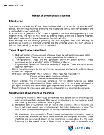
Lecture NotesElements of Electrical MachinesAny two winding transformer can be converted into an autotransformer either step-down or stepup. If we employ additive polarity between the high voltage and low voltage sides, we get a step-uptransformer. If, however, we use the subtractive polarity, we get a step-down autotransformer. Theconnections are given in fig.2.Fig.5.2 A two winding transformer connected as an autotransformer in various waysFig.5.3 Autotransformer or Variac30
Lecture NotesElements of Electrical MachinesFig.5.4 3 – Phase autotransformer connectionSynchronous MachinesA synchronous machine operates at constant speed in the steady state. Under steady stateconditions, the rotating air gap field and the rotor in a synchronous machine rotate at the same speed,called the synchronous speed which depends on the frequency of the armature current and the number offield poles. Synchronous machines are used primarily as gemerators of electric power. In this case theyare called alternators. Synchronous generators are the primary energy conversion devices of the worldselectric power systems today.6.1Construction of three phase synchronous machinesA synchronous machine consists of two main parts namely, an armature winding and a magneticfield, similar to a dc machine. The following are the main advantages of rotating field type synchronousmachines.(a) Two slip rings are required for the supply of direct current to the rotor while in stationary fieldtype 3 to 4 slip rings would be needed.31
Lecture NotesElements of Electrical Machines(b) The power used in exciting the field system may be only about two percent of the ac output of themachine and that too is supplied at low voltage, thus it is easier and economical to design sliprings to carry this smaller power for the rotating field.(c) The voltage generated in the armature is much higher and therefore greater insulation is requiredfor the armature winding. Thus it is much easier to insulate the high voltage winding when it ismounted on a stationary structure.(d) Note that by the use of stationary armature this high voltage insulation is not subjected tomechanical stress due to centrifugal forces. The end conductors of the armature winding can bebraced securely in position thereby making it fit to withstand the large forces by sudden shortcircuit.(e) The main connecting cables can be connected directly with the armature winding. With rotatingarmature, the current would have to be calculated by means of slip rings and with high voltageand large power, such collection, would pose serious problems.(f) Rotating field is comparatively light and can be constructed for high speed operation.(g) Cooling systems are comparatively easier.6.1.1StatorThe stator of a three phase synchronous machine consists of a stator frame, a slotted stator, whichprovides a low reluctance path for the magnetic flux. It has a distributed winding embedded in the slotssimilar to that of three phase induction machine.6.1.2RotorThe rotor has a winding called the field winding, which carries direct current. The field windingon the rotating frame is normally fed from an external dc source through slip rings and bruses. Two typesof rotors are used in synchronous machines, the cylindrical rotor and a salient pole rotor. Depending onthe type of rotor used synchronous machines are broadly divided into two groups as follows: High speed machines with cylindrical (non- salient pole) rotors32
Lecture Notes Elements of Electrical MachinesLow speed machines with salient pole rotorsThe cylindrical rotor has one distributed winding and an essentially uniform air gap. These rotorsare used in large generators with two or sometimes four poles and are usually driven by steam turbines.The rotors are long and have a small diameter. The features are, They have small diameters and very long axial length. Dynamic balancing is better. Operation is quieter and windage losses are less. The speed is 1000 to 3000 rpm. Used with steam turbines and steam engines.The rotors of salient pole machines have concentrated winding on the poles and a non-uniform airgap. Salient pole generators have a large number of poles, sometimes as many as 50, and operate at lowerspeed. The alternators in hydroelectric power stations are of the salient pole type and are driven by waterturbines. The rotors are shorter in length but have a large diameter. The speed is 120 to 400 rpm.6.2Equation of induced E.M.F.Let, flux per pole in weberz total number of armature conductors or coil sides in series/phase 2TT no. of turns or coils per phaseP no. of generator polesf frequence of induced emf in HzN rotor speed in revolutions per minute (rpm)K d distribution factor sin m / 2 msin / 2 K c or K P pitch or coil span factor cos 2K f form factor33
Lecture NotesElements of Electrical MachinesIn one revolution of the rotor (i.e. in 60 / N seconds) each conductor is cut by a flux of P weber.Hence, d P and dt 60secondsNHence, average emf induced/conductor Now, we know that f d NPvolts, n 1 dt60PN120 for N 120PSubstituting this value of N above, we getAverage emf induced/conductor P 120 f60 P 2 f voltsIf there are z no. of conductors in series/phase, then average emf/phase 2 f z volts 4 f T voltsHence,RMS value of emf/phase 4.44 f T voltsThis would have been the actual value of the induced voltage if all the coils in a phase were,(i)full pitched, and (ii)concentrated or bunched in one slot. But this is not being so, the actually availablevoltage is reduced in the ration of these two factors.Hence, actually available voltage/phase 4.44K c K d f T volts 4K f K c K d f T voltsIf the alternator is star connected then the line voltage is6.2.13 times the phase voltage.Short-Pitch WindingAdvantages Copper in end connection can be saved. Harmonics are reduced Iron losses will be reduced Efficiency will be increased Generated voltage waveform will be improved is more sinusoidal.34
Lecture NotesElements of Electrical MachinesDisadvantages: 6.2.2The magnitude of the induced voltage will be reducedDistributed WindingAdvantages The generated voltage waveform will be improved, is more sinusoidal.Disadvantage 6.3The magnitude of induced voltage will be reducedSynchronous motorA synchronous motor runs under steady state condition at
An electric motor is a machine which converts electrical energy into mechanical energy. 2.1 Principle of operation It is based on the principle that when a current-carrying conductor is placed in a magnetic field, it experiences a mechanical force whose direction is given by Fle