Transcription
PRO Installation1
Designed by the pros for the prosThere are a lot of choices when it comes to buying a thermostat,but only one combines 125 years of experience and the latestconnected home technology to empower your customersto take control of their comfort from anywhere. We proudlyconnect you to a professional-grade thermostat that youcan offer your customers with confidence and that will keepyou connected with them even after the initial install.Sensi partner programAlways be the Contractor-On-Call with your customers.The Sensi app saves your contact information so when yourcustomer needs service, you’re just a tap away. Register atwww.sensiregistration.com.Need help?Visit sensicomfort.com/support for around-the-clockaccess to support articles, instructional downloadsand comprehensive support videos. Our highly-trainedSensi Support Team is available seven days a week.1.888.605.7131support@sensicomfort.com2
Easy to install and connectSensi is designed to install like a standard thermostat. Itgives you the flexibility to connect to Wi-Fi at installationor let your customer connect it later using the Sensi app.MOBILE DEVICE COMPATIBILITYOPERATING SYSTEMCOMPATIBILITYiOSYesAndroidYesAmazon FireYesSMART HOME PLATFORM COMPATIBILITYOPERATING SYSTEMCOMPATIBILITYAmazon AlexaYesGoogle AssistantYesApple HomeKitYes, but requires acommon wire (c-wire)Sensi SmartThingsYes3
HVAC SYSTEM COMPATIBILITYSYSTEM TYPECOMPATIBILITYMODIFICATIONSConventional heating andcooling Gas furnace Air conditioner Electric furnace BoilerYesNoneHeat only Gas furnace Electric furnace BoilerYesRequires a commonwire (c-wire)Cool only Air conditionerYesRequires a commonwire (c-wire)Heat pumpYesRequires a commonwire (c-wire)Communicatingproprietary systemsNoNeeds standard HVAC wiringLine voltageNoRequires low voltage(20-30VAC)Millivolt systemsNoRequires 20-30VACROUTER COMPATIBILITYROUTER TYPECOMPATIBILITYSingle-band router with 2.4 GHz bandYes*Dual-band router with 2.4 & 5.0 GHz bandsYes*Single-band router with 5.0 GHz bandNo*Sensi thermostats require an 802.11n 2.4 GHz Wi-Fi network and are compatible with most residentialWi-Fi networks, however there are some known incompatible routers. Visit support.sensicomfort.comand search “router compatibility” for a list of known incompatible routers.4
What’s in the box? Sensi Thermostat Screws and Anchors Wire Labels 2 AA Batteries Sensi Security Code(found on the back of the Welcome Guide)Items needed for Wi-Fi connection: The homeowners compatible iOS or Android devicewith the Sensi app installed and registered Your customer’s Wi-Fi network name (SSID) and passwordQUICK TIP: Ask the homeowner to download theSensi app and gather their Wi-Fi informationwhile you are installing the thermostat.5
Installation1. Install Sensi thermostat, referring to these terminaldefinitions, cross references and wiring diagrams as needed:SENSITHERMOSTATCONVENTIONAL SYSTEMCONNECTIONHEAT PUMPSYSTEM CONNECTIONRC†Power for cooling, 24VRH†Power for heating, 24VCCommon wire, 24VY1st stage cool1st stage heat and cool(compressor)Y2/*2nd stage cool(or humidifier)2nd stage heat andcool (or humidifier)W/E1st stage heat1st stage auxiliary/emergencyheat (2nd stage heat)W2/*2nd stage heat(or dehumidifier)2nd stage auxiliary/emergency heat (3rd stageheat or dehumidifier)GIndoor blower (fan)O/BHeat pump changeover, zoneHeat pump changeoverpanel or 3-wire hot water zone (reversing valve) connectionvalve connection. (configurable (configure as O or B inas O, B or 2 in the installer menu) the installer menu)Lno function† Two transformer systems (separate RC and RH wires), clip internal jumper locatedon back of Sensi above battery compartment.†† L abel “B” as “C” only if the old thermostat also had a wire in “O”. If there is no wireon “O”-label the wire “B”.†††6“L” terminalconnection On Heat Pump system with separate W2 and E wires, label both wires W/E(2 wires in one terminal).
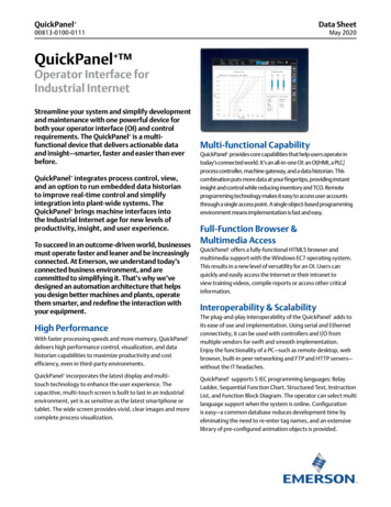
Two transformers systems (separate RC and RH wires), clip internal RC/RH jumper, located on back of thermostat.NEUTRALCooling TransformerHOT120 VACHOTHeat pump changeover, zone panel or3-wire hot water zone valve connection.(configurable as O, B or 2in the installer menu)24 VACNEUTRALDots IndicatePhasedRelationshipHeat Pump L terminal connectionDehumidifier(if configured fordehumidification)2nd stage heat(or dehumidifier)Thermostat1st stage heatHumidifier(if configuredfor humidification)2nd stage cool(or humidifier)1st stage coolCommon wire, 24VPower for heating, 24V††Heating TransformerHOT120 VACNEUTRALMulti-Stage(AC2, GA2, EL2)Dots IndicatePhasedRelationshipSingle Stage(AC1, GA1, EL1)NEUTRAL24 VACHOTPower for cooling, 24VSystemConfigurationCONVENTIONAL SINGLE STAGE OR MULTI-STAGE SYSTEMS (NO HEAT PUMP)Indoor blower (fan) energizedon call for fan, cool or electric heat7
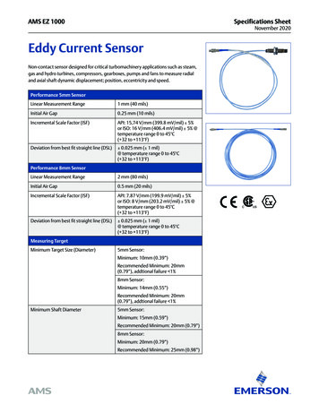
1st stage auxiliary/emergency heat(3rd stage heat)Humidifier(if configuredfor humidification)2nd stage heat andcool compressor††1st stage heat and cool compressorCommon wire, 24V8Power for cooling, 24VSystemConfigurationHEAT PUMP SYSTEMS†Power for heating, 24VHeat PumpSingle StageHP1Heat PumpMulti-StageHP224 VACNEUTRALHOT†Internal jumper between RC and RH, located on back of thermostat.Common connection required on Heat-only, Cool-only or Heat Pump systems.1st stage auxiliary/emergency heat(2nd stage heat)††Thermostat2nd stage auxiliary/ 2nd stage auxiliary/emergency heatemergency heat(3rd stage heat(4th stage heator dehumidifier)or dehumidifier)120 VACHOTIndoor blower (fan) energizedon call for fan, cool or heatNEUTRALHeat pump changeover (reversing valve)connection (configure as O or Bin the installer menu)Dots IndicatePhasedRelationshipHeat Pump L terminal connection
2. After installation, configure the thermostat to theappropriate system type. Press “Menu” on the thermostatand refer to these menu options as needed:CONFIGURATION MENU ITEMS REFERENCEMenu itemDescriptionOptionsOutdoor EquipmentSelect AC or Heat Pumpequipment, as well asthe number of stages.Set this to AC1 for singlestage systems or HP1 orHP2 for single or multistage heat pumpsAC1/AC2/HP1/HP2/NoneIndoor EquipmentSelect whether theequipment is an electricor gas furnace, or fanonly. Set this to EL1 forsingle stage electric orGA1 or GA2 for single ormulti-stage gas systems.GA1/GA2/EL1/EL2/FanReversing ValvePositionWhen configured for O,reversing valve is energizedin Cooling. This will covermost applications. Somemanufacturers such asRheem or Rhudd use theB terminal, which wouldenergize in heating. Forthree-wire zone hydronicsystems set this to Z.O/B/6/NoneHumidifier(wired tothermostat)If a humidifier is wired tothe thermostat, change theHumidifier setting to YESYes/NoDehumidifier(wired tothermostat)If a dehumidifier is wired tothe thermostat, change theDehumidifier setting to YES.Yes/NoAdditionalAccessories
3. Once the thermostat is installed and properly configured,test the equipment by following these steps: Turn on power to the system. Fan Operation If your system does not have a “G” terminalconnection, skip to “Heating System” below. Press the “Fan” button on the thermostat and select the“On” position. The blower should begin to operate. Press the “Mode” button to turn off the system. Thenpress the “Fan” button on the thermostat and select the“Auto” position. The blower should stop immediately. Circulating Fan Press the “Menu” button on the thermostat and pressthe “Next” button until you reach the “Fn” screen. Adjust the % run time from 10%-100% in 5%increments by using the arrow up or downbuttons (default is OFF), then press “Exit”. The % run time is the percentage of time thefan shall run in a day. This calculation takes intoaccount the amount of time the heating, cooling andcontinuous fan have run during the same day.10
Heating System Press the “Mode” button on the thermostatand select the “Heat” position. Press the up arrow on the thermostat and adjust the settingto 1 above the current room temperature. The heatingsystem should begin to operate and the thermostat willindicate “Heating” of “Heating Auxiliary” on the screen. For heat pumps with auxiliary, press the up arrowon the thermostat and adjust the setting to 3 above the current room temperature. The auxiliaryheat should begin to operate and the thermostatwill indicate “Heating Auxiliary” on the screen. Press the down arrow on the thermostat and adjust thesetting to 1 below the current room temperature. Theheating system should stop operating and “Heating” or“Heating Auxiliary” will disappear from the screen.11
Auxiliary System (only for heat pumps with auxiliary) Press the “Mode” button on the thermostat andselect the “Aux” position. This bypasses theheat pump and runs auxiliary-only heat. Press the up arrow on the thermostat and adjust thesetting to 1 above the current room temperature. Theauxiliary heating system should begin to operate and thethermostat will indicate “Heating Auxiliary” on the screen. Press the down arrow on the thermostat and adjustthe setting to 1 below the current room temperature.The auxiliary heating system should stop operating and“Heating Auxiliary” will disappear from the screen.12
Cooling System Press the “Mode” button on the thermostatand select the “Cool” position. Press the down arrow and adjust the setting to 1 belowthe current room temperature. The blower should come onimmediately on high speed, followed by cold air circulation.The thermostat will indicate “Cooling” on the screen. Notethat there can be up to a 5 minute delay for this process.This is indicated by a flashing setpoint temperature. Press the up arrow and adjust the setting to 1 above thecurrent room temperature. The cooling system should stopoperating and “Cooling” will disappear from the screen. If you encounter any issues while testing the equipment,refer to the troubleshooting actions on page 17.13
Humidification Press the “Mode” button on the thermostatand select the “Heat” position. Press the up arrow on the thermostat and adjust thesetting to 1 above the current room temperature.The heating system should begin to operate and thethermostat will indicate “Heating” on the screen. Press the “Menu” button on the thermostat and pressthe “Next” button until you reach the “H SP” screen. Turn Humidification On by pressing either the Up orDown button until the humidity set point is higher thanthe current room humidity. Humidity can be adjustedfrom 5%-50% in 5% increments, then press “Exit”. Check to ensure humidifier is running. Press the down arrow on the thermostat andadjust the setting to 1 below the current roomtemperature. The heating and humidificationsystems should both stop operating.14
Dehumidification Press the “Mode” button on the thermostatand select the “Cool” position. Press the down arrow and adjust the setting to 1 belowthe current room temperature. The blower should come onimmediately on high speed, followed by cold air circulation.The thermostat will indicate “Cooling” on the screen. Notethat there can be up to a 5 minute delay for this process.This is indicated by a flashing setpoint temperature. Press the “Menu” button on the thermostat and pressthe “Next” button until you reach the “dH SP” screen. Turn Dehumidification On by pressing either the Up orDown button until the humidity setpoint is lower thanthe current room humidity. Humidity can be adjustedfrom 40% to 95% in 5% increments, then press “Exit”. Depending on installed equipment, check that the systemfan speed has slowed, the dehumidifier is running,or the system cools up to 3 below temperature setpoint or until the humidity set point is reached. Press the up arrow and adjust the setting to 1 abovethe current room temperature. The cooling system anddehumidifier (if applicable) should both stop operating.15
TroubleshootingSYMPTOMPOSSIBLE CAUSECORRECTIVE ACTIONNo Heat/No Cool/No Fan(commonproblem)1. B lown fuse ortripped circuitbreaker1. R eplace fuse or reset breaker2. Furnace powerswitch to OFF3. F urnace blowercompartmentdoor panel loose2. T urn switch to ON3. R eplace door panel in properposition to engage safetyinterlock or door switch4. T ighten connections4. L oose connectionto thermostator systemNo Heat1. T hermostat notset to Heat2. Loose connectionto thermostator system3. H eating systemrequires serviceor thermostatrequiresreplacement161. Set thermostat to Heat.2. V erify thermostat and systemwires are securely attached.3. D iagnostic: Set Mode to Heat andraise the setpoint above roomtemperature. Within five minutesthe thermostat should make asoft click sound and “Heating”should appear on display. Thissound indicates the thermostatis operating properly. If thethermostat does not click, tryresetting the thermostat. Ifthe thermostat does not clickafter being reset, contact yourheating and cooling serviceperson or place of purchase fora replacement. If the thermostatclicks, verify the heating systemis operating correctly.
SYMPTOMPOSSIBLE CAUSECORRECTIVE ACTIONNo Cool1. T hermostat notset to Cool1. S et thermostat to Cool.2. Loose connectionto thermostator system3. C ooling systemrequires serviceor thermostatrequiresreplacement2. V erify thermostat and systemwires are securely attached.3. D iagnostic: Set Mode to Cooland lower setpoint below roomtemperature. Same procedures asdiagnostic for “No Heat” conditionexcept set the thermostat to Cooland lower the setpoint below theroom temperature. There may beup to a five minute delay beforethe thermostat clicks in Cooling ifthe AC Protection feature is on.Heat, Coolor Fan RunsConstantlyPossible short inwiring, thermostat,heat, cool orfan systemCheck each wire connectionto verify they are not shortedor touching other wires. Tryresetting the thermostat.ThermostatDisplay &ThermometerDisagreeThermostat displayrequires adjustmentDisplay can be adjusted /-5 usingthe Temperature Offset in Sensi app.17
SYMPTOMPOSSIBLE CAUSECORRECTIVE ACTIONHumidityDisplay &HygrometerDisagreeHumidity displayrequires adjustmentDisplay can be adjusted in 5%increments /-25% using theHumidity Offset in the Sensi app.Furnace (AirConditioner)Cycles TooFast or SlowThe location of thethermostat and/or the size of theHeating Systemmay be influencingthe cycle rateDigital thermostats provide precisecontrol and cycle faster than oldermechanical models. The system turnson and off more frequently, but runsfor a shorter time. If you would liketo increase cycle time, choose Slowfor the Cycle Rate in the Sensi app.“ C all forService”appears onthe screen1. H eating or Coolingsystem is notable to heat/cool the space towithin 5 degreesof the setpointwithin 2 hours1. S ee corrective action for“No Heat” or “No Cool”2. If “--” is displayedfor the RoomTemperature,a replacementthermostatis needed2. R eplace thermostat3. M ake sure keypad lockout isnot turned on. If it’s OFF, tryresetting the thermostat.Reset: Turn the power to yoursystem off, wait 5 secondsand turn it back on.3. N one of thebuttons operateon the thermostatFan turns onrandomly18The fan hasbeen set to runoccasionally in theconfiguration menuEnter the configuration menuand make sure the ‘Fn’ fan runtime percentage is OFF.
Connecting Sensi to Wi-Fi1. A sk the homeowner to download the free Sensi app onto theiriOS or Android device.2. A sk the homeowner to follow the prompts to createan account.3. Once the homeowner has logged in, ask to use their device toconnect the thermostat to the Wi-Fi.QUICK TIP: You must have your customer’s Wi-Fi Network(SSID) and Password, along with the Sensi Security Codecard to complete the wireless setup.4. S elect “Connect Thermostat to WiFi” and follow the in-app prompts tocomplete the connection steps.5. O nce the thermostat is connectedto Wi-Fi, enter your registered phonenumber by selecting “Contractor” fromthe drop down menu.19
WarningsINSTALLER INFORMATIONFAILURE TO READ AND FOLLOW ALL INSTRUCTIONS CAREFULLY BEFORE INSTALLINGOR OPERATING THIS CONTROL COULD CAUSE PERSONAL INJURY AND/OR PROPERTYDAMAGE.WARNING: OUT OF PHASETRANSFORMERSOn two transformer systems, thetransformers MUST be in phase.Measure the voltage across RCand RH. If more than 12 Volts AC ispresent between RC and RH, thenthe transformers are NOT in phase.To correct this condition, reverse thesecondary low voltage connectionsat either the Heating or Coolingtransformer.To prevent electrical shock and/or equipment damage, disconnectelectric power to system atmain circuit breaker box untilinstallation is complete.FOR CALIFORNIA RESIDENTS:WARNING:This product contains a chemicalknown to the state of California tocause cancer and birth defects andother reproductive harm.20VOLTAGE REQUIREMENTSDo not use on circuits exceedingspecified voltage. Higher voltage willdamage control and could causeshock or fire hazard.Thermostat installation and allcomponents of the control system shallconform to Class II circuits per the NECcode.CAUTION: E5 AlertIf “Call For Service” is displayed onyour Sensi thermostat, and E4 or E5appears where the room temperatureshould be displayed or the backlightis flashing, please call our supportteam immediately at 888.605.7131ATTENTION: MERCURY NOTICEThis product does not contain mercury.However, this product may replacea product that contains mercury.Mercury and products containingmercury must not be discarded inhousehold trash. Refer to thermostatrecycle.org for location to sendproduct containing mercury.
For Your CustomerMAKE SURE TO LEAVE THE SENSI WELCOME GUIDE FORYOUR CUSTOMER.It provides helpful instructions and information on the following: Includes their Sensi Security Code for connecting to Wi-Fi How to connect their Sensi thermostat to Wi-Fi (if this hasnot already been completed) or connect additional devices Key features of the thermostat and the app and how they work Customer Support21
0037-7678004
Heat Pump Single Stage HP1 Power for cooling, 24V Power for heating, 24V Common wire, 24V 1st stage heat and cool compressor Indoor blower (fan) energized on call for fan, cool or heat Heat pump changeover (reversing valve) connection (configure as O or B in the installer menu) Heat Pump L terminal connection 2nd stage heat and cool compressor