Transcription
Basic Duct Leakage TestingFrank SpevakThe Energy Conservatory Copyright 2014 The Energy Conservatory Presentation
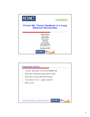
Housekeeping This webinar is being broadcast by computer only. If you can not hear please check your computersettings for your audio and the volume of yourspeakers. This webinar is being recorded and will be on theTEC website in the near future for you to review. Please ask questions throughout the webinar andwe will get to them at the end. Ask your questionby typing it in the chat box.2
Housekeeping For CEU credit – the maximum is 1.25 CEUthrough BPI. Be aware that your activity on your computer willinfluence the amount of the CEU credit. CEU credit will be determined by BPI and will be creditedto you soon after the completion of the webinar. If you have not provided your BPI number, please sendan email to editor@energyconservatory.com and includeyour full name, company and BPI number.3
Housekeeping We will be showing how to set up TEC equipment. Most of the information can be used regardless ofthe manufacturer of the equipment. Thank you for attending today.4
The Energy ConservatoryOur mission is to make buildings more energyefficient through the development and manufactureof diagnostic tools.5
The Energy ConservatoryWe provide the most comprehensive and extensivetechnical support to our customers on the use ofMinneapolis Blower Door , Minneapolis DuctBlaster and all of the equipment we manufacture.6
Learning Objectives#1: Learn about the current and future codes as theyrelate to duct leakage#2: Learn how to perform a number of tests tomeasure duct leakage#3: Learn what the results mean and the effects ofduct leakage in a house7
Agenda Overview of the IRC & IECC Code Status andRequirements DET and IDL Duct Testing Types of testing Procedures for testing What do the numbers mean?8
IRC and IECC IRC addresses all topics related to residentialconstruction– Structural, plumbing, electrical, mechanical etc.– Allows builder to carry only one code book– Chapter 11 covers energy efficiency IECC addresses only energy IECC addresses both residential and commercial The IRC has incorporated the residential energyprovisions of the IECC9
IECC10
Section R402.4.1.2 Section N 1102.4.1.2(R402.4.1.2)11
http://bcap-energy.org/12
13
What We Have Learned There 17 states that have not adopted IECC 2009as the state energy code contrary to each of thestates accepting federal funds that required theadoption of the energy code. States are free to adopt the I Codes by referenceand then modify with State specific amendments– These amendments can make important clarifications.– The State of Georgia’s Amendments to the IECC will bediscussed as an example14
Modifications to Code Individual jurisdictions within a state are takingindependent action to the state – both to be stricterand to be less strict.– El Paso County, CO - Stricter– Anonymous County, CA – Exempting all duct testing Many code officials are still learning what the codeis, what tests are required and what to do with thetest results. Always check with your local jurisdiction regardingrequirements.15
PA Amendments Tests shall be conducted in accordance withANSI/ASHRAE 152-2004, Method of Test forDetermining the Design and Seasonal Efficienciesof Residential Thermal Distribution Systems.16
State Amendments to the 2009 DET– Certified– Duct & EnvelopeTightness Verifier17
GA Amendments HERS RatersHome Performance with Energy Star ContractorBPI Building AnalystOr complete a Certified DET course18
19
Illinois Amendment20
Illinois Amendment Use DET verifier program developed by Southface butadapted to Illinois requirements.21
Louisiana Requirement Nationally recognized certification program––––BPIHERSDET not nationally recognizedIDL (Infiltration and Duct Leakage) from BPI Brand new Considered nationally recognized22
What We Have Learned Adoption to the code is slow but will continue. More education is needed throughout the system.–––––––State energy officeCode developers – IECC and StateCode officialsInspectorsBuildersContractorsHome owners23
2009 IECC 403.2.2Duct Tightness Tests Duct tightness shall be verified Post construction– 2 Methods Leakage to outdoors: 8 cfm/per 100 ft2 of conditioned floor areaorTotal leakage: 12 cfm/per 100 ft2 of conditioned floor area– tested at a pressure differential of 25pa (0.1 in w.g.) across entiresystem, including manufacturer’s air handler enclosure All register boots shall be taped or otherwise sealed during thetest.24
2009 IECCSECTION 403 403.2 Ducts. 403.2.1 Insulation– Supply ducts in attic shall be insulated to a minimum ofR-8.– All other ducts shall be insulated to a minimum of R-6.– Exception: Ducts or portions thereof located completelyinside the building thermal envelope.25
Ducts 403.2.2 Sealing (Mandatory) All ducts, air handlers, filter boxes and buildingcavities used as ducts shall be sealed– Joints and seams shall comply with IRC, SectionM1601.4.1 Building framing cavities shall not be used assupply ducts26
IECC SECTION 4032009 403.2.2 Sealing (mandatory)– All ducts, air handlers, filterboxes and building cavities usedas ducts shall be sealed 403.2.3 Building Cavities(mandatory)– Building framing cavities shallnot be used as supply ducts2012 403.2.2 Sealing (mandatory)– Ducts, air handlers and filterboxes shall be sealed 403.2.3 Building Cavities(mandatory)– Building framing cavities shallnot be used as ducts orplenums27
28
29
Conditioned Space Leakage30
Leakage to the Outside31
Duct Leakage Interactions32
Interior Cavity Leakage33
34
35
36
37
38
Duct Insulation Exception: Ducts or portions thereoflocated completely inside the building thermalenvelope39
Exception: Ducts or portions thereof locatedcompletely inside the building thermal envelope40
Testing Types of Duct Leakage Tests– Total Duct Leakage– Duct Leakage to Outside Set-up for Total Duct LeakageSet-up for Duct Leakage to OutsideDiscussion of Leakage ResultsDuct Blaster Calibration41
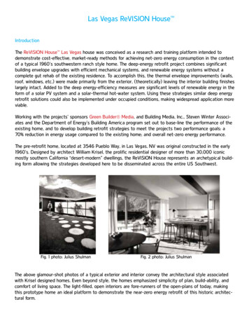
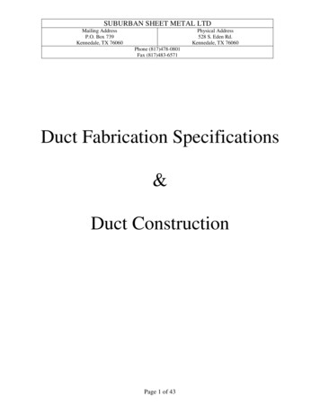
Types of Duct Leakage Tests Total Duct Leakage (required in 2009 and 2012)– Pressurize (or depressurize) duct work.– Duct Blaster connected to central return or air handler.– Measure air flow (CFM) needed to pressurize ducts to 25Pa.– Measures all duct leaks.42
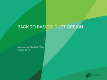
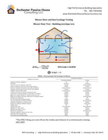
Types of Duct Leakage Tests Duct Leakage to Outside (required in 2009 but notallowed in 2012)––––Pressurize (or depressurize) duct work.Duct Blaster connected to central return or air handlerBlower Door operating to pressurize house to 25 Pa.Measure air flow (CFM) needed to equalize pressure inducts to 0 Pa.– Measures only duct leaks to outside the buildingenvelope (e.g. attics, crawlspaces, garages).43
Duct Leakage Test Results Rough-in test (air handler installed)– Total leakage 6 cfm/per 100 ft2 of conditioned floor area tested at a pressure differential 25Pa (0.1 in w.g.) acrossroughed-in system all register boots taped or otherwise sealed44
Duct Leakage Test Results Rough-in test (air handler not installed)– Total leakage 4 cfm/per 100 ft2 of conditioned floor area tested at a pressure differential 25Pa (0.1 in w.g.) acrossroughed-in system all register boots taped or otherwise sealed45
Types of Duct Leakage Tests Total Duct Leakage– Measures all duct leaks.– Pressurize (or depressurize) duct work.– Duct Blaster connected to central return or airhandler.– Measure air flow (CFM) needed to pressurizeducts to 25 Pa.46
Types of Duct Leakage Tests Duct Leakage to Outside– Measures only duct leaks to outside the buildingenvelope (e.g. attics, crawlspaces, garages).– Pressurize (or depressurize) duct work.– Duct Blaster connected to central return or airhandler– Blower Door operating to pressurize house to25 Pa.– Measure air flow (CFM) needed to equalizepressure in ducts to 0 Pa.47
Conditioned Space versus EnclosureExceptions: Duct tightness test is not required if the airhandler and all ducts are located within conditioned space48
Total Leakage Test (Pressurization)49
Total Leakage Test Connect the Duct TestingFan to either:– The largest return grille, or– The blower access door.50
Total Leakage Test Install the Flow Ring on the fan that you thinkbest matches the needed fan flow (can alwayschange Ring during test). Now have Ring 451
Total Leakage Test Turn off the air handler sothat it does not come onduring test. Temporarily seal off allremaining supply andreturn registers usingpainters tape, Duct Maskor other temporary seal.52
Total Leakage Test Turn off exhaust fans, dryers etc. Remove all filters from the duct system. Open a door or window between the houseand outside (prevents changes in housepressure during the test), and interior doors. Open access doors from unconditionedspaces (e.g. attics) containing ducts tooutside.53
Total Leakage Test Select a location to measureduct pressure.– Either in the supply plenum,supply trunk, or at a supplyregister.– In a tight duct system (i.e. 200 CFM25), location choicewill have very little effect onresults.– In zoned systems, must havedampers open, or will need totest each supply run separately(this is a big problem).54
Total Leakage Test Connect tubing to the DG-700Gauge.– Green tubing from duct pressureprobe to Input of Channel A.– Red tubing from Duct Blaster fanto input of Channel B.55
Total Leakage Test Put DG-700 in PR/ FL @25 Mode, enter Deviceand Configuration, adjust fan to about 25 Pa ductpressure on Channel A.– Gauge displays CFM25 on Channel B. (Can’tReach 25 Factor is built-in to the flow reading)– Saves time - no need to adjust test pressure toexactly 25 Pa - just get close (20 - 30).– In very leaky duct systems, displays leakageestimate if Duct Pressure is at least 5 Pa.56
Outside Leakage Test (Pressurization)57
Outside Leakage Test When possible, unconditioned zonescontaining ducts shall be opened to outsideand conditioned zones containing ducts shallbe opened to inside. If this is not possible,leave as is. Windows and doors to outside must beclosed. Prepare house for a Blower Door test.– Water heater on pilot.– Turn off heating and cooling system.58
Outside Leakage Test Seal off all registers and returns as in a Total DuctLeakage Test. Duct Testing Fan set up is the same as Total LeakageTest. Install Blower Door fanto pressurize house(not measuring flowfrom Blower Door fan).59
Outside Leakage Test (Blower Door) Start DG-700 gauge onthe Blower Door and goto the Cruise Mode. Set for 25 Pa. Start fan to maintainhouse at 25 Pa.60
Outside Leakage Test With Duct Blaster DG-700,connect tubing to the gauge(same as Total Leakage Test).– Green tubing from duct pressureprobe to Input of Channel A.– Red tubing from Duct Blaster fanto input of Channel B.61
Outside Leakage Test Put DG-700 in PR/ FL Mode (not PR/ FL @25),enter Device and Configuration. With Blower Door pressurizing building to 25 Pa,adjust Duct Blaster to create zero pressurebetween ducts and building (Channel A). Flowvalue from Channel B is the measured leakage.62
Total vs. Outside Leakage TestTotal Leakage Test:Pro: Con: Can do test at rough-in.Shorter set-up time/easier test.Less equipment needed.Often results in larger leakage measurement thanOutside test (unless all ducts are outside of the building). Harder to meet Energy Star requirements if leakagenumber is bigger. If testing at rough-in, often have to accept penalty formissing register grilles (2.5%), and missing air handler(2.5%).63
Total vs. Outside Leakage TestOutside Leakage Test:Pro: Often results in smaller leakage measurement thanTotal test (unless all ducts outside). Easier to meet Energy Star requirement if leakagemeasurement is smaller.Con: Longer set-up time. More equipment needed (Blower Door). Must wait until building envelope completed beforeconducting test.64
Tips and Troubleshooting When performing a Leakage to Outside Test, performa Total Leakage Test first to determine if house passeswithout the Outside Test. Provides you with a maximum leakage number. TheOutside Test can not have a number larger than theTotal Test. Remember, for Outside Test, have the gauge in PL/FLmode not PL/FL@25 mode – common error.65
Leakage Results How much duct leakage is acceptable? Use California as example (all ductwork is usuallyoutside building envelope)– For Retrofit Total duct leakage can not exceed 15% of rated flow ofair handler, or Reduction of total duct leakage by 60%. (Requires a pretest of duct leakage) Energy Star– For New construction 6 cfm leakage to the outside per 100 sq. ft. of floor area.66
Leakage Results How much leakage are we talking about? Retrofit:– House system has 2 ½ tons of cooling.– At 400 CFM per ton equals 1,000 CFM.– Retrofit @ 15% 150 CFM25 of total leakage. New construction:– 1000 square feet– Energy Star @ 6% equals 60 CFM25 of leakageto the outside67
Duct Leakage Impacts Example –– Outside duct leakage test results are 300 CFM25on a 2 ½ ton system.– Assuming the leaks are split equally betweensupply and return, the result is a 22.5% annualenergy penalty.– A 12 SEER system is now only 9.3.– An 80% furnace is now only 62%. Duct Leakage to Outside is a direct energypenalty for heating and cooling.68
Leakage Results Any duct leakage that is outside of the buildingenvelope creates an energy penalty as well as airquality problem. Duct leakage to the inside is not a large energypenalty, but can contribute to problems related todelivery of air, comfort issues and other problemsrelated to pressurization or depressurization of thehouse. Be aware that sealing all ductwork can cause otherproblems related to the air handler or combustionsafety.69
Duct Blaster Field Calibration Plate Used to perform a fieldcalibration check on yourSeries B Minneapolis DuctBlaster System (with DG700 gauge). Designed to simulate a ductleakage test with a leakagerate of 106 CFM @25 Pa.70
Finding Leaks71
Foggers72
73
74
IR75
76
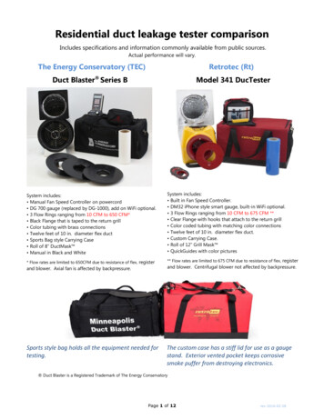
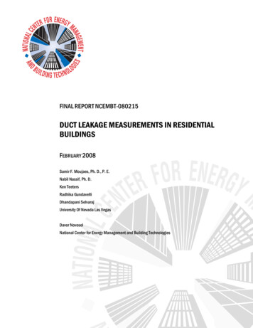
Duct Diagnostics Using A Blower Door Duct Leakage Diagnostics: Pressure Pan test to determine if duct work isconnected to the outside.With Blower Door maintaining 50 Pa, test registerswith Pressure Pan.Qualitative test.Helps find dominantleak to the outside.77
Duct Diagnostics Using A Blower Door Blower Door Subtraction–––––Test total envelope leakageof house.Seal all registers.Test house again.Compare test results withregisters sealed andunsealed.Result should be ductleakage to outside.78
Tools For Finding Leaks Blower doors Infrared Scanners Smoke pencils andtheatrical fog79 79
More Useful Information Fan Calibration Fans maintain their calibration unless physicaldamage occurs.These conditions are easily detected and shouldbe tested for on a regular basis.80
Main Issues Affecting FanCalibration The 2 most importantaspects to maintainingproper fan calibration: No leaks in flow sensor.Sensor in properposition. Damaged fan housing(e.g. broken flange) andbroken/ missing blades.81
Flow Sensor Position Because the Blower Doorand Duct Blaster flowsensors are connected to themotor, the motor determinesthe sensor position. Motors can move if fan isdropped, or motor mountscan bend.motormountmotor82
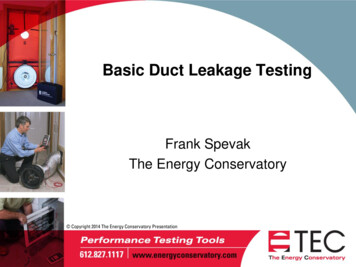
Checking Flow Sensor Position Measure the distancebetween the inlet plane ofthe fan housing and theface of flow sensor. Distance for a Duct Blasterfan should be between7/16” to 9/16”. Adjustsensor position. Return to TEC to replacebent motor mounts ordamaged props.83
Digital Gauge Calibration Calibration is recommended once every twoyears. Calibration is performed at TEC factory. Cost is 100 and is usually completed in about3 or 4 days. Blower Door and Duct Blaster manualsdescribe how to perform a calibration check inthe field. Upgrade of older DG-700 to Cruise is an extra 50 on top of recalibration.84
More Useful Information Visit our new website(www.energyconservatory.com) Articles on airsealing and duct leakage diagnostics. Previous newsletters. All product manuals and guides are online. Video Quick Guides for Blower Door and DuctBlaster Links to other sites. Download latest version of Software.85
Thank You86
Types of Duct Leakage Tests Duct Leakage to Outside (required in 2009 but not allowed in 2012) -Pressurize (or depressurize) duct work. -Duct Blaster connected to central return or air handler -Blower Door operating to pressurize house to 25 Pa. -Measure air flow (CFM) needed to equalize pressure in ducts to 0 Pa.