Transcription
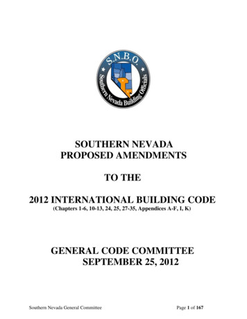
Las Vegas ReVISION House IntroductionThe ReVISION House Las Vegas house was conceived as a research and training platform intended todemonstrate cost-effective, market-ready methods for achieving net-zero energy consumption in the contextof a typical 1960’s southwestern ranch style home. The deep-energy retrofit project combines significantbuilding envelope upgrades with efficient mechanical systems, and renewable energy systems without acomplete gut rehab of the existing residence. To accomplish this, the thermal envelope improvements (walls,roof, windows, etc.) were made primarily from the exterior, (theoretically) leaving the interior building finisheslargely intact. Added to the deep energy-efficiency measures are significant levels of renewable energy in theform of a solar PV system and a solar-thermal hot-water system. Using these strategies similar deep energyretrofit solutions could also be implemented under occupied conditions, making widespread application moreviable.Working with the projects’ sponsors Green Builder Media, and Building Media, Inc., Steven Winter Associates and the Department of Energy’s Building America program set out to base-line the performance of theexisting home, and to develop building retrofit strategies to meet the projects two performance goals: a70% reduction in energy usage compared to the existing home; and overall net-zero energy performance.The pre-retrofit home, located at 3546 Pueblo Way, in Las Vegas, NV was original constructed in the early1960’s. Designed by architect William Krisel, the prolific residential designer of more than 30,000 iconicmostly southern California “desert-modern” dwellings, the ReVISION House represents an archetypical building form allowing the strategies developed here to be disseminated across the entire US Southwest.Fig. 1 photo: Julius ShulmanFig. 2 photo: Julius ShulmanThe above glamour-shot photos of a typical exterior and interior convey the architectural style associatedwith Krisel designed homes. Even beyond style, the homes emphasized simplicity of plan, build-ability, andcomfort of living space. The light-filled, open interiors are fore-runners of the open-plans of today, makingthis prototype home an ideal platform to demonstrate the near-zero energy retrofit of this historic architectural form.
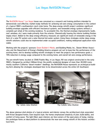
Fig. 3Front elevation of ReVISION House Las VegasFig. 4 ReVISION House Las Vegas Existing Plan
Existing Home Energy AnalysisTo baseline the energy performance of the existing residence SWA initially performed testing on 3546Pueblo Way in Las Vegas, Nevada on September 3rd, 2009. This audit was intended to investigate anddocument all the relevant performance related building specifications as they currently exist including building envelope, glazing, HVAC systems, hot-water, lighting, and appliances. Evaluation of this home included:1.2.3.4.Air leakage test: Minneapolis Blower DoorInfrared Scan: Flir B50 IR cameraDuct leakage test: Minneapolis Duct BlasterVisual inspection of components including insulation levels, equipment capacities and efficiencies,window types, etc.Air leakage was analyzed using the blower door in conjunction with the infrared (IR) camera. By scanningthe home before it is depressurized and then again while the blower door is running, the inspector can tellwhere air is entering an assembly. Air leakage often looks like tendrils of hair through the IR camera helpingthe auditor to differentiate between a simple conduction problem and an air leak. Also, cavities affected byair leakage will appear cooler or warmer with the blower door running than they did before the blower doorwas turned on. Using this diagnostic technique, air leakage can be detected in areas where it cannot befelt. More importantly, the point of origin of big air leaks can usually be detected.After the initial IR scan was conducted, the home was depressurized to 50 pascals with a MinneapolisBlower Door. The resulting flow reading was 2,725 cfm50 which equates to 7.5 air changes per hour @ 50pascals (ACH50). Quantitatively this is a moderate amount of leakage, and less than originally anticipated.Leak locations and magnitudes were detected by feel and with the IR camera in the following locations: The gas fireplace: this lacked glass doors and, because a gas inlet was present, the damper wasfixed in the open position (as required by code). A significant amount of air was pulled down thechimney. Ceiling mounted recessed can lights: there were several can lights in the ceiling of this home. Theceiling is a vented, closed cathedral configuration insulated with fiberglass batts in the rafter bays.Significant air leakage could be felt and imaged coming from these recesses light fixtures.Fig. 5:Infrared Picture Showing Air Leakage from a recessed can light
The duct chases/dropped ceiling: There were a few dropped ceilings to accommodate the ductwork coming down from the roof mounted air handlers. These areas communicated freely with thevented rafter spaces. The below images show the affects of this air movement through the insulation in the kneewalls and rafters.Fig. 6:Infrared Images Showing Air Leakage in Dropped Soffits and Rafter Bays Single pane, aluminum frame windows: Even when completely closed and locked, these windowsleaked. Air was coming from the fixed windows as well as the operable ones. Outlets and switch plates: Air could be felt coming from these areas as well as seen with the IRcamera. Interior wall penetrations leaked as much as exterior walls due to the connection with thevented roof.Fig. 7: Infrared Image Showing Leakage from Electrical OutletsEven though the overall leakage is considered moderate, because this is a slab-on-grade home, most significant leaks occur through insulated assemblies, seriously degrading the ability of the insulation to performas the intended thermal barrier. In addition to finding air leaks, the IR camera was used to detect thermalbypasses in the building shell. Besides the bypass in the kneewalls noted above, other problems areas included the corners, the wall/roof connection at the top plate around penetrations into the roof from lighting,smoke detectors, exhaust fans and heating/cooling registers. The following images of the ceiling were takenbefore noon on the southeast side of the house with the temperatures already over 100 degrees F outside.
Fig. 8:Infrared Scan Showing Ineffectiveness of Insulation in CeilingBoth of these IR images were taken prior to the blower door test. From these images it is clear that heatis getting around the insulation. In a well insulated cavity where it is much hotter outside than inside, thewood rafters should appear warmer than the cavity because they have a lower insulating value and thecolors in the images would be reversed. The framing members should be yellow to red and the cavitiesgreen to blue in comparison. In the existing assembly the R-30 cavity insulation performed worse than the2 x 10 rafters (approximately R-12).HVAC SystemsThere were two heating/cooling systems conditioning this home; both roof mounted Tempstar gas furnaceswith central air conditioning units each with heating capacities of 80 kBTU/hr and 36 kBTU/hr of coolingfor a total heating capacity of 160,000 BTU/h for heating and 72,000 BTH/h for cooling. Model and serial number nameplates were used to determine listed equipment efficiencies which were noted to the 0.80AFUE and SEER 10 for heating and cooling respectively.Both systems were tested for total duct leakage and leakage to the outside. Duct leakage tests were conducted per the Minneapolis Duct Blaster Operation Manual’s pressurization protocol. The results are summarized in Table 1 1.Table 1 1 Duct Leakage Test ResultsSystem #1System #2Total Leakage(cfm@25)258.0170.0Total:428.0Leakage to theOutside(cfm@25)154.0115.0269.0Leakage toOutside(%)11%9%10%*Total system flow is estimated to be 1350 cfm/air handler based on air handler flow testsand flow measurements at registers.Based on accepted practice, it is assumed that the air handlers were sized to deliver 450 cfm/ton of coolingfor this climate resulting in a total flow of 1,350 cfm per air handler. At this flow rate, leakage to the outside is approximately 10% of the total flow to the conditioned space.Walls and ceiling cavities were opened to verify cavity depths, insulation levels and quality of installation.The following existing energy related specifications were determined:
Walls were found to be 3-1/2” in depth containing fiberglass batts, approximately R-11. The vaulted rafter cavities are 9” deep and also contain fiberglass batts which are the fulldepth of the cavity, approximately R-30 nominally. The dropped ceiling areas were insulated on the flat ceiling and the kneewalls with fiberglassbatts, approximately R-38 & R-19 respectively. The ductwork, though insulated, was run in these cavities on top of the insulation leaving it inunconditioned space. No slab edge insulation was installed. Windows were single pane with metal frames in most cases. No storms were present. The water heater, located in the garage, was a 50 gallon, natural gas atmospheric unit in, presently leaking and beyond its useful life.Even though the insulation levels appear to be reasonable, the infrared camera indicated that the cavityinsulation is performing worse than the framing materials in each location. This means that the ceilingwas performing worse than an R-11.25 and walls worse than an R-3.75 effective value (based on the thermal gradient generated by the IR imagery. The kneewall insulation appeared to be completely ineffective.The performance goals for this project are to approach and potentially reach net-zero energy consumption on an annualized basis. To achieve this, the project team focused on getting the major building loadsas low as practical; applied very high-efficiency equipment to the resultant loads; and sized renewableenergy systems to match the annualized consumption of kilowatt-hours. Working within the structuralconfines of the existing building shell, and while leaving the majority of interior finishes intact, thermalenvelope options were somewhat more limited than usual but none-the-less available.Performance Optimization and ZEH SpecificationsUsing EnergyGauge USA 2.8.03, multiple parametric analyses were conducted to determine the optimalbalance of wall and roof insulation values, glazing U-factors and solar heat gain coefficients (SHGC), andenvelope tightness levels, again with the intent of minimizing, to the degree practical, space heating andcooling loads. Exterior walls are 2x4 framing, and with the interior finishes to remain, additional space forinsulation cannot be obtained toward the interior, so an exterior foam sheathing solution was developed.Closed-cell spray polyurethane foam (ccSPF) and open-cell spray polyurethane (ocSPF) were looked atfor the cavity fill while an EIFS solution was selected for the foam sheathing and exterior finish. Basedon the optimization study and the required R-value in the R-21 range, ocSPF was selected as the fillinsulation, with 2” EPS foam for the EIFS.The roof is low pitch (2/12) 2 x 10 rafters with the pitched rafters forming the sloped ceiling plane formuch of the house, thus most of the roof insulation must be within the rafter cavities, or above theroof decking. Given the extreme summer heat encountered in this location a heat-rejection strategy wasdeveloped for the roof covering. This consists of a “cool” standing seam metal roof over a 1-1/2” ventedspace. With this in place we reviewed options for the rafter cavity fill and selected a very aggressiveR-55 and specified 8.5” of ccSPF to achieve it.A small attic space exists above the entry hall and bedroom corridor. The cool-roof and rafter insulation strategy here is the same as the vaulted ceiling portions of the home, except that an ignition andthermal barrier needed to be added below the rafters to protect the foam insulation as no drywall
ceiling existed at this location. As access from the bottom of the rafters is height restricted, supportledgers and horizontal furring were applied to the bottom of the rafters from above, and the gypsumboard thermal barrier placed in the rafter cavities from above to rest on the furring and ledger supports.The extensive glazing in this home is integral to its iconic design, so the design team had three options inimproving the performance of the glazing in this home to near-ZEH levels: select very high-performancesouthern glass; eliminate glass where incompatible to the interior space served; or do both. The thirdapproach was selected with the existing single-glazed aluminum framed units replaced with triple low-eunits (U-0.22, SHGC-0.19). The rear facing French doors (prior replacement units) were to be replacedwith sliders in keeping with the original 1960’s design.Because the front of the home faces west and the major rooms occupying that elevation are two bedrooms, the extensive clerestory glazing in that elevation presents a huge solar-gain and cooling load, withlittle day-lighting or other benefit. Although modeling indicated substantial energy benefit in eliminatingthat glazing, the design team was concerned about altering the front appearance of this iconic home.Working with EIFS supplier and manufacturing partner Dryvit , a design solution was arrived at wherethe front facing trapezoidal clerestory glass would be eliminated and replaced with a contrasting EIFS finish with a dark, reflective surface mimicking the glass.Initial air-leakage envelope assumptions were borne out by envelope testing which resulted in 7.5 ACH50results. As the entire thermal-boundary of the home will be made up of ccSPF and ocSPF, air leakageassumptions for the completed home were anticipated to be in the 2.0 ACH50 area. The majority of leakpoints remaining following completion were anticipated to be between the concrete slab and the wallframing, and the typical leak points around the sliding door and glazing components.In hot-dry Las Vegas, cooling is a denominate cumulative energy load, as well as a dominate peak energyload. A key strategy when aiming for a net-zero energy outcome is therefore reducing the cooling load asmuch as practical. One component of this is rejecting heat energy before it has the chance to penetratethe thermal envelope. Because this one story home has a large roof-to-floor area ratio, and the roof isimpacted with very significant solar loading, a “cool-roof” strategy was adopted. A cool-roof is defined asa roof covering which maintains a level of solar reflectance at 0.65 (for a low sloped roof, which is 2/12or less as defined by ASTM Standard E 1918-97). With these criteria in mind, the design team selected astanding seam metal roof with a solar reflectance (SR) and thermal emittance (TE) above the minimumthresholds as define by the Cool Roof Ratings Council (CRRC).To further improve the solar heat rejection performance, the standing seam roof was installed over a1-1/2” vented space with continuous vents at the eaves and at the ridge. Earlier studies by OakridgeNational Lab (Miller, W., et al, 2007) found up to 30% heat rejection capability using the “above-sheathing-ventilation” (ASV) approach alone. SWA also isolated two sets of three contiguous vented bays forside-by-side temperature monitoring of a roof deck radiant barrier strategy versus a standard roofing underlayment. Given the aggressive solar heat rejection strategy adopted, the question of how much moreheat-rejection performance beyond the vented cool-roof can be obtained is one the design team desiredto answer. Data collection was initiated in July 2010 and early results show an approximate 15 degreereduction in peak temperature in the radiant barrier rafter bay versus the standard rafter bay. This resultis encouraging based on research team expectations.
Once the building enclosure specifications were finalized, alternate mechanical systems were investigatedbeginning with HVAC equipment. Initially the design team was intrigued with a very high performanceductless mini-split heat-pump system. The high efficiency ratings and the ductless configuration wouldallow for a relatively non-obtrusive retrofit, which the design team felt fit well with the occupied retrofitmessage. Other considerations, including first-cost, forced an alternate, more conventional ducted heatpump system to be selected. The existing design of the home, with the centrally located ceiling drops(which contained the existing ducts) provided an ideal location for the redesigned compact duct layoutto be placed inside-the-conditioned-space. To replace the two roof mounted air-handlers, a single, interiorfloor mounted vertical air handler was chosen. A single return, central to the floor plan was placed at thebase of the AHU, with a sound baffle to mitigate blower fan noise.Manual J sizing determined a 3-ton capacity with the peak heating and cooling being closely matched.The dry Las Vegas climate permitted a higher than typical sensible-heat-ratio of 0.85 for improved sensible performance and better comfort. The Trane equipment combination provides a SEER of 18 for cooling, and a HSPF of 8.5. Along with the single-zone variable-speed system, programmable user controlsand automated air filtration sections were selected for improved indoor-air-quality.The design team initially investigated a separately ducted energy-recovery-ventilator (ERV) for the(ASHRAE 62.2-2010) required fresh air ventilation. Energy modeling found that even with an 80% efficient ERV, the net BTU energy savings would be less than the operational energy cost, and the decisionwas made to go with an exhaust-only strategy. SWA has excellent experience and performance test datawith this type system, and given that this home does not have an attached garage or radon concerns,exhaust only ventilation Panasonic WhisperGreen fans (model number FV08VKSI) were selected. Localregulations require an exhaust fan for the laundry closet, which, being centrally located in the plan, wasthe fan selected to be programmed for constant flow to meet ASHRAE 62.2 ventilation standards.As a net-zero-energy home in a hot-dry climate, the inclusion of solar hot water was very desirable. Theselected system consists of an EagleSun DBS (drain back system). The DBS drain back is unique in thatit contains an integrated 10 gallon drain back tank with integrated pump on top of the 60 gallon storage tank for quicker and easier installation. Modeling estimated a 75% solar contribution. When the solarcontribution does not meet the full hot water demand, a Rinnai natural-gas tankless water heater willmake up the difference. Plumbed in series with the solar, the tankless water heater uses the solar hotwater as a pre-heat tank. If the water supplied from the tank is 130 degrees F, the Rinnai won’t activate;is less than 130 F it will. The very compact nature of the tankless unit allows installation central to thehot water use in the house reducing losses.The home had been largely renovated in the 1990’s including replacing all the kitchen appliances. Evenso the existing refrigerator, dishwasher, range and laundry appliances were not near as efficient as newerEnergyStar devices. With EnergyStar qualified appliances, a range of performances is available with onlythe minimum performance levels being indicated. All appliances will be replaced with new, higher thanminimally performing EnergyStar qualified devices.The existing permanently installed lighting fixtures were fully documented and placed into the energymodel along with the default operation and use schedule. Because the fixtures were so numerous, and
inefficient (100% incandescent), the resulting energy use is significant, even as a percentage of theenergy in the existing home (1971 kWh) a year. To control costs and to obtain the performance levels desired, a hybrid strategy was selected to reuse many of the existing fixtures, and re-lamp them with highefficacy devices, both compact fluorescent and LED. To accommodate the existing recessed fixtures inthe sloped ceiling, metal enclosures were fabricated and fitted over the fixtures prior to the foam insulation application. The new metal jacket allows the foam to be sprayed against the device while providinga small air space between the insulation and the heat generating lamp.An integrated lighting control system was also planned since most of the existing lighting and switchwiring could be made compatible with that application. Time-of-day controls, dimmers, group “activitysettings” controls and options further allow the occupant to fine-tune and adjust the artificial lighting tospecific needs, activities and time-of-day to reduce energy use even further. These efforts provided for anearly 75% reduction in predicted lighting energy down to 551 annual kWh.The cumulative improvement to the homes’ energy performance was predicted to bring the energy usedown to about 9000 kWh from 30,000 kWh a year. To get to the net-zero energy goals, the designteam matched the remaining power needs with on-site renewables, in this case a 6 kilowatt SunPowerPV system. Even though the roof surface faces a non-ideal southeast (versus true south), the low roofslope limits the performance de-rate more than a steeper slope would, and excellent production can stillbe obtained. The 500 square foot 6kW system is predicted to produce 9621 kWh annually, resulting innet-zero performance.Construction Process:Initial demolition and removals commenced late November 2009. Because the finished project was intended to be a completed “show home” to be displayed at the International Builders Show (IBS) in earlyFebruary a very compressed timeframe added logistical difficulty. As a result, building processes andcrews overlapped throughout the project.Building Envelope UpgradesExterior stucco and board-and-batten finishes were stripped exposing the original stud cavities. Theill-fitting fiberglass batts (nominally R-11) were also removed leaving the frame cavities void. The interiordrywall (much of which had been previously replaced due to a fire in the 1990’s) was left in place, keeping the interior wall finishes largely intact. The carport, which had been previously changed to a garage,was gutted, bringing it back to the original carport function. Having exposed the wall framing cavities,minor electrical work could be accommodated from the exterior, and additional hose-bibs could beadded. Once accomplished, the open-cell spray foam was added to the frame cavities, and raked flush.Fig. 9: Exposed wall framingFig. 10: Open-cell foam insulationFig. 11: Exterior EIFS
Structural sheathing in the form of CDX plywood was added as Las Vegas in is a high-risk seismic zoneand the home previously lacked much in the way of lateral bracing. Two Simpson Strong-Tie “StrongWall ” panels were also added at the rear elevation which is predominately glass.Following the sheathing application an EIFS (exterior-insulation-finish-system) was added over 2” of EPSfoam insulation. Cumulative R-value of the upgraded wall is 21.25. The EIFS has multiple benefits forthis project: it mimics the stucco removed from the existing walls; it is a complete system including theexterior foam, thus providing R-value and thermal breaks; and it comes with complete water managementdetails for around windows, door, penetrations and base terminations. Most other thick foam applications require fussy and expensive alternate detailing.With the extensive glazing and the low-performance capabilities of the existing windows, the fenestration represented a real weak-link in the buildings envelope performance. The replacement units, a combination of double and triple glazed low-e fiberglass units were custom fabricated to fit the existingopenings and install easily. The flange-type frames married well with the EIFS creating a relatively simpleoperation. The large trapezoidal units above the rear sliders were too big to fabricate as triples, so ratherthan subdivide the glass, high performance double glazed windows were selected. These face north, sothe increase in SHGC has little performance impact.Work on the roof proceeded using a similar strategy, with all roof covering and the roof decking removedleaving the rafter framing and the ceiling gypsum board attached to the bottom of the sloped rafters.Where a sloped ceiling did not exist (but a small attic space did) ledgers were attached along the bottom edge of the rafters and gypsum board was laid onto the ledgers. All 2 x 10 rafter spaces were thenfilled with 8.5” of closed-cell foam leaving a small 1” void at the top. The result is an R-55.25 assemblywith outstanding air-sealing.Fig. 12: Applying Closed-cell foam at rafters Fig. 13: 8.5” of foam in 2 x 10 raftersRafter foam insulation was followed by plywood roof decking; a drainage underlayment membrane, crosslapped furring strips; and a fully vented “cool” metal roof.Fig. 13: Decked roof with vent spaceFig. 14: Metal roof installation
Mechanical System UpgradesThe first step in reaching the ultimate performance goal is getting the building envelope loads down as lowas practical. The next step is to meet those loads with the most efficient mechanical systems practical.For the ReVISION House this included complete replacement of the HVAC systems using the specifications described above. Since the plan was altered slightly for the inclusion of the air-handler in conditionedspace (in a small centrally located closet) and the redesigned ducts are accommodated in the now-inconditioned-space attic loft, integrating the new SEER 18 heatpump, went smoothly. The zero-leak objective for the ducts was emphasized, as was the testing requirement, so the installer had additional motivation to see that the install was virtually leak-free. The installer did make minor adjustments to the registerlocations (although CARB felt them to be unnecessary). Operation or comfort was not affected by thechanges.Fig. 15: Revised HVAC designIn efficient homes, domestic hot water can be the largest load, so as described in the specificationsabove, the design team was aggressive in attacking it. Using the drainback solar thermal system as adirect pre-heat, and the tankless gas unit as a backup raised questions by both the solar manufacturerand the tankless water heater manufacturer. CARB has had good experience with this arrangement in thepast, and convinced both manufacturers of its viability. Two changes occurred during installation due tonon-availability of a 60 gallon storage tank: an eighty gallon tank was substituted; and because of the additional tank height, the drainback reservoir tank needed to be relocated and not directly mounted on topof the tank.
ASHRAE 62.2 ventilation remained as specified using an exhaust only approach and a Panasonic WhisperGreen fan, but since the municipality insisted on an exhaust fan for the laundry “room” (really a closet),CARB decided to use that centrally-located device as the prime whole-house ventilation fan, with the twoother bath fans as spot exhaust.Prior to the foaming of the roof rafters, a strategy allowing the existing recessed can light housings wasdeveloped. Small sheet metal cylindrical spacers were fabricated and placed over the devices creating a 1/2”air space between the devices and the insulation. A minimum of 3” of closed cell foam covered the tops ofthe spacers. During this phase the lighting wiring circuits were traced and labeled, allowing the later installation of the Lutron control system. Only minimal rewiring was required.Final Testing and Inspection Results:Following completion of construction Steven Winter Associates conducted final testing on 3546 Pueblo Wayin Las Vegas, Nevada on February 28, 2010. Evaluation of this home included:1.2.3.4.Air leakage test: Minneapolis Blower DoorInfrared Scan: Flir B50 IR cameraDuct leakage test: Minneapolis Duct BlasterVisual inspection of components.Blower Door ResultsAir leakage was analyzed using the blower door in conjunction with the infrared (IR) camera. By scanningthe home before it is depressurized and then again while the blower door is running, the inspector can tellwhere air is entering an assembly. Air leakage often looks like tendrils of hair through the IR camera helpingthe auditor to differentiate between a simple conduction problem and an air leak. Also, cavities affected byair leakage will appear cooler or warmer with the blower door running than they did before the blower doorwas turned on. Using this diagnostic technique, air leakage can be detected in areas where it cannot befelt. More importantly, the point of origin of big air leaks can usually be detected.After the initial IR scan was conducted, the home was depressurized to 50 pascals with a MinneapolisBlower Door. The resulting flow reading was 800 cfm50 which equates to 2.2 air changes per hour @ 50pascals (ACH50). Prior to the retrofits, the air leakage rate was approximately 7.5 ACH50. This is a 71%reduction in air leakage due to air sealing and insulating the walls and ceiling with spray foam insulation.The majority of the remaining air leaks appeared tobe coming from the following locations: The fireplace: Originally supplied with anatural gas option, the fireplace lacks glass doorsand, by code, the flue damper was sealed in theopen position. Sealed glass doors were recommended after initial testing, but designers chose toleave the fireplace as built, with the exception ofremoving the gas-line and altering the damper to beoperational. Further sealing of the fireplace duringFig.16:Livingroomfireplace
the blower door test showed that an additional 120 CFM@50 could be eliminated if the fireplacehad been better sealed. This amounts to 15% of the air leakage detected during the final testing. Slab/bottom plate connection: consiste
Both systems were tested for total duct leakage and leakage to the outside. Duct leakage tests were con-ducted per the Minneapolis Duct Blaster Operation Manual’s pressurization protocol. The results are summa-rized in Table 1 1. Table 1 1 Duct Leakage Test Results Total Leakage Leakag