Transcription
FINAL REPORT NCEMBT-080215DUCT LEAKAGE MEASUREMENTS IN RESIDENTIALBUILDINGSFEBRUARY 2008Samir F. Moujaes, Ph. D., P. E.Nabil Nassif, Ph. D.Ken TeetersRadhika GundavelliDhandapani SelvarajUniversity Of Nevada Las VegasDavor NovoselNational Center for Energy Management and Building Technologies
FINAL REPORT NCEMBT-080215NATIONAL CENTER FOR ENERGY MANAGEMENT ANDBUILDING TECHNOLOGIES TASK 05-11: DUCTLEAKAGE MEASUREMENTS IN RESIDENTIALBUILDINGSFebruary 2008Prepared By:Samir F. Moujaes, Ph. D., P. E.Nabil Nassif, Ph. D.Ken TeetersRadhika GundavelliDhandapani SelvarajUniversity Of Nevada Las VegasDavor NovoselNational Center for Energy Management and Building TechnologiesPrepared For:U.S. Department of EnergyWilliam HaslebacherProject Officer / ManagerThis report was prepared for the U.S. Department of EnergyUnder Cooperative Agreement DE-FC26-03GO13072
NOTICEThis report was prepared as an account of work sponsored by an agency of the United States government. Neither theUnited States government nor any agency thereof, nor any of their employees, makes any warranty, express orimplied, or assumes any legal liability or responsibility for the accuracy, completeness, or usefulness of anyinformation, apparatus, product, or process disclosed, or represents that its use would not infringe privately ownedrights. Reference herein to any specific commercial product, process, or service by trade name, trademark,manufacturer, or otherwise does not necessarily constitute or imply its endorsement, recommendation, or favoring bythe United States government or any agency thereof. The views and opinions of authors expressed herein do notnecessarily state or reflect those of the United States government or any agency thereof.UNIVERSITY OF NEVADA LAS VEGAS CONTACTSamir F. Moujaes, Ph.D., P.E.Associate ProfessorDeptartment of Mechanical Engineering4505 Maryland ParkwayBox 454027Las Vegas, NV 89154-4027(702) 895-3265samir@me.unlv.eduNATIONAL CENTER FOR ENERGY MANAGEMENT AND BUILDING TECHNOLOGIES CONTACTDavor NovoselChief Technology OfficerNational Center for Energy Management and Building Technologies601 North Fairfax Street, Suite 250Alexandria VA 5
TABLE OF CONTENTSEXECUTIVE SUMMARY.11. PROJECT OBJECTIVE.32. BACKGROUND.43. METHODOLOGY .53.1 Air Duct Leakage Laboratory .53.2 Zone DeltaP Method to Locate and Quantify duct leaks.73.3 Derivation of the Zone DeltaP Relationships .83.4 Zone DeltaP Test Procedure .103.5 Modifications and Improvements .143.6 Method for Determining Suppy and Return Leakage Rates When Physical Separation Is Not Possible .154. RESULTS .174.1 Analytical Validation.174.2 Experimental Validation.225. CONCLUSION .286. REFERENCES.30APPENDIX A. AIR DUCT LEAKAGE LABORATORY.33APPENDIX B. INSTRUMENTATION .36B.1 Zone Bags .36B.2 Duct Blaster .36B.3 Teclog .37B.4 Blower Door.39B.5 DG 700 Pressure and Flow Guage .40B.6 Automated Performance Testing System.41B.7 Register Sealing Film .42B.9 Visual Inspection System .42B.10 Pressure Pan .43APPENDIX C: BASELINE TESTING .44C.1 Parametric Studies on Zone Bags.44C.2 Test Procedure .47C.3 Baseline Local Leakages.50APPENDIX D. FLOW CHARACTERSTIC OF HOLES.53APPENDIX E. CHARACTERISTICS OF AIR DISTRIBUTION SYSTEM.55APPENDIX F. DUCT DISTRIBUTION MODEL .56NCEMBT-080215v
APPENDIX G. OVERVIEW OF DUCT LEAKAGE MEASUREMENT METHODS .57G.1 Duct Pressurization Test .57G.2 DeltaQ .57G.3 Nulling Test .58viNCEMBT-080215
LIST OF FIGURESFigure 1. Layout of the Air Duct Leakage Laboratory .6Figure 2. Zone Bag Assembly.7Figure 3. Schematic of the Zone DeltaP Method .8Figure 4. Potential Zone DeltaP Test Sequence for ADS1 .12Figure 5. Potential Zone DeltaP Test Sequence for ADS2 .13Figure 6. Method for Determining Supply and Return Leakage Rates When Physical Separation Is Not Possible.16Figure 7. Histograms For Normal Distribution Errors With A Standard Deviation Of 1 Applied To Pressure And FlowValues .18Figure 8. Comparison of Simulated Zone DeltaP Results vs. Assigned Leakage Rates for ADS1 with Different Errors(1%, 2%, 3% and 4%) Applied to the Flow and Pressure Values .19Figure 9. Comparison of the Assigned Leakage Rates and Simulated Results Using the Zone DeltaP Method ApplyingNormal Distribution Errors with Standard Deviations (Σ) of 1% (Left) and 4% (Right).20Figure 10. Comparison of the Total Assigned Leakage Rate and Simulated Results Using the Zone DeltaP, DuctPressurization and DeltaQ Method Applying Normal Distribution Errors with Standard Deviations (Σ) of 1% .21Figure 11. Comparison of Baseline Results with Zone DeltaP Ones .23Figure 12. Hole in the Supply Plenum of ADS1 .24Figure 13 Comparison of Known Local Leakages From Holes with Those Measured by the Zone DeltaP Method .26Figure 14 Comparison of Known Total Supply Leakages from Holes with Those Measured by the Investigated Methods.26Figure 15. Air Duct Leakage Laboratory as Seen from the East Side With the Heat Pump Servings ADS2.33Figure 16. Soffits for Air Distribution Systems (ADS) 1 and 2 .34Figure 17. Truss Structure in Soffits .34Figure 18. Zone Bag with a Nominal Size of Eight Inches .36Figure 19. Minneapolis Duct Blaster.37Figure 20. Screenshot of TECLOG .38Figure 21. Flow and Pressure Readings Along With Summary Statistics Provided by TECLOG when the Duct System IsPressurized.38Figure 22. Typical Blower Door Setup.39Figure 23. DG 700 Pressure Gauge by The Energy Conservatory .40Figure 24. Automatic Performance Testing System Manufactured by The Energy Conservatory.41Figure 25. Duct Mask by Conservation Strategies .42Figure 26. Visual Inspection System .43Figure 27. Pressure Pan by Conservation Strategies .43Figure 28. Duct Caps Used For Parametric Studies On The Zone Bag.44Figure 29. T section with the Zone Bag .45NCEMBT-080215vii
Figure 30. Effectiveness of the Zone Bags in 8” Straight Duct For Different Pressures Inside the Duct and Zone Bags.46Figure 31. Effectiveness of the Zone Bags in 8” Tee Duct Section for Different Pressures Inside the Duct and ZoneBags.46Figure 32. Steps Used for Determining the Local Leakages of ADS1 .48Figure 33. Steps Used for Determining the Local Leakages of ADS2 .49Figure 34. Local Leakage as a Function of the Leak Pressure for ADS1.50Figure 35. Local Leakage as a Function of the Leak Pressure for ADS2.51Figure 36. Flow Characteristics of the 20 Holes Introduced on the Boot of the Grilles .53Figure 37. Fan performance Curves for ADS1 and ADS2 .55viiiNCEMBT-080215
LIST OF TABLESTable 1. Correction factors (CF) for the Zone DeltaP method .9Table 2. Mean Difference (MD) and Mean Absolute Difference (MAD) as Determined by Comparing the AssignedLeakages vs. Simulated Results Obtained Using the Zone DeltaP Method.20Table 3. Mean Difference (MD) and Mean Absolute Difference (MAD) as Determined by Comparing the TotalAssigned Leakages vs. Simulated Results Obtained Using Different Duct Leakage Methods.21Table 4. Comparison of Baseline Local Leakages and Zone DeltaP Measured Values for ADS1 and ADS2 .22Table 5. Total Supply Leakage Rate As Determined By The Various Methods .24Table 6. Comparison of Mean Absolute Difference (MAD) and the Mean Different (MD) for Both ADS1 and ADS2 forthe Four Investigated Duct Leakage Measurement Methods.27Table 7. Specifications of the Air Conditioning Systems.34Table 8. Duct Blaster Specifications .37Table 9. Blower Door Specifications.39Table 10. DG-700 Pressure and Flow Gauge Specifications.40Table 11. Automated Performance Testing (APT) System Specifications.41Table 12. Visual Inspection System Specifications .42Table 13. Operational Range of Pressures for the Zone Bag .45Table 14. Leak Pressures and Flows for ADS1 .51Table 15. Leak Pressures and Flows for ADS2 .52Table 16. Total Leakages for ADS1 and ADS2 with Different Combinations of Opened or Closed Holes Located onBoots of Different Grilles .54NCEMBT-080215ix
xNCEMBT-080215
EXECUTIVE SUMMARYEXECUTIVE SUMMARYDuct leakage in forced-air distribution systems has a significant impact on the energy consumed inresidential buildings. It is a common practice to place the ducts outside the conditioned space in a largeportion of US homes. This can result in significant loss of energy by leakage to the outside on the supplyside and the infiltration of unconditioned air into the system on the return side. Field studies have shownthat existing residential air distribution systems can leak as much as 40% of the total supply air. As ductsare often outside the conditioned space, this leakage corresponds to a proportionate amount of energy lossfrom the duct system.Several methods for estimating duct leakage have been used in the past with varying degrees of accuracy.One of the widely used techniques is the Duct Pressurization Test. In this test, the total supply or returnleakage is estimated by measuring the flow from a calibrated fan into the duct system at a specific testpressure (usually 25 Pa) using the blower door measurement technique. More recently, DeltaQ andNulling tests have been proposed to determine both total supply and return duct leakage rates.The DeltaQ test is an extension of the Duct Pressurization Test using the same blower door measurementtechnique. It measures air leakage flows for the ducts and the building envelope over a large range ofpressures with the air handler on and off. The supply and return are leakages are determined from thefitting curves of the difference between the air handler off and on blower door flows at each pressurerecording station. The DeltaQ test forms the basis for ASTM Standard E1554-03 “Determining ExternalAir Leakage of Air Distribution Systems by Fan Pressurization”. Similarly, the Nulling test uses acalibrated fan to counteract the pressure change across the envelope due to duct leakage.All of these techniques focus on determining the total supply and return leakages irrespective of where theleaks are located along the air distribution system. However, the location and nature of the leak may beparticularly important for selecting an appropriate method to mitigate leaks more cost effectively than theexisting methods. Therefore, a method that simultaneously measures the “local” and “total” leakages isneeded as a means of targeting resources on leaky homes and on portions of ducts that have the mostproblems.The goal of this project was to develop a new measurement method for locating and estimating the localand total leakage rates. To achieve this goal, the following steps were performed: (i) an experimentalfacility, the Air Duct Leakage Laboratory (ADLL), was set up at UNLV; (ii) a validation procedure forthe new measurement method was developed; (iii) a test protocol for the developed technique wasestablished; and (iv) the new measurement method was analytically and experimentally validated in theADLL.The new measurement method, named Zone DeltaP, was derived from the duct pressurization techniquein which the duct system is pressurized by using a calibrated fan while all registers are sealed off. Zonebags are used to create artificial restrictions inside the duct and consequently different levels of leakpressures and flows. When the zone bag is inflated inside the duct, two different levels of pressures andleak flows (upstream and downstream of the zone bag) are artificially created. A very simple calculationis then performed to estimate the leakage in these two locations. The tests can be repeated to measure theleakages in different locations.The Zone DeltaP test offers several advantages over existing measurement methods. It determines thequantity of each leak within the air distribution system, i.e., it pinpoints where in the air distribution theleak is located and its rate of leakage. Thus, duct repair efforts can be focused on the most leakylocations. Other advantages of the Zone DeltaP Test are: (i) it estimates the duct leakage to outside orinside without the need to perform the house-Duct Pressurization Tests simultaneously as described inNCEMBT-0802151
EXECUTIVE SUMMARYAppendix A of ASHRAE Standard 152-2004, (ii) it reduces the uncertainty associated with convertingthe leakage at an artificial pressure (e.g. 25 Pa) to leakage at the operation pressures, and (iii) it solvescertain practical problems associated with duct pressurization technique, e.g., the difficulty to separate thesupply from the return leakages or the problem of an inaccessible air handler cabinet.The report presents results from an extensive laboratory and simulation evaluation. It also providesinsight of the performance of several current measurement methods such as Duct Pressurization Test,DeltaQ, and Nulling test for comparison with the newly developed Zone DeltaP Test.2NCEMBT-080215
PROJECT OBJECTIVE1. PROJECT OBJECTIVEThe main objective of this project was to develop and validate a measurement method for locating andestimating the leakages in typical residential air distribution systems. The specific goals of this projectwere: Develop a new measurement methods to locate and quantify leakages in residential airdistribution systems Validate the new measurement methods numerically and experimentally Compare the new measurement methods to establish protocols, such as Delta Q, DuctPressurization Test and Nulling Test.NCEMBT-0802153
BACKGROUND2. BACKGROUNDDuct leakage in forced-air distribution systems has a significant impact on the energy consumed inresidential buildings (Jump et al. 1996, Siegel et al. 1998, Davis et al. 1998, Walker et al. 1998, Siegel etal. 2003 and Francisco et al. 2002a, 2002b, 2003). It is a common practice to place the ducts outside theconditioned space in a large portion of US homes. This can result in significant loss of energy by leakageto the outside on the supply side and the infiltration of unconditioned air into the system on the returnside. Field studies have shown that existing residential systems typically lose 40% of the total supply airin the form of duct leakage (Jump et al. 1996; Cummings et al. 1990; Downey and Proctor 1994; Moderaand Wilcox 1995). As ducts are often outside the conditioned space, this leakage corresponds to aproportionate amount of energy loss from the duct system (Sherman et al 2000). There are also comfort,humidity and indoor air quality problems associated with return leaks drawing air from outside orunconditioned spaces within the structure (Francisco et al 2002 and Francisco et al 2003). In addition, asystem with more supply than return leakage causes increased infiltration of air that must be conditioned(Sherman et al 2000).Several methods for estimating duct leakage have been used in the past with varying degrees of accuracy.One of the widely used techniques is the Duct Pressurization Test that is part of ANSI/ASHRAE Standard152-2004 (ASHRAE 2004). In this test, the leakage is estimated by measuring the flow from a calibratedfan into the duct system at one test pressure (e.g. 25 Pa). Generally, the measurement method here is thesame as for a blower door test (Sherman 1995, ASTM 2003b). The approach is to mask of all registersand pressurize the duct system either from the air handler or a return grille using a calibrated fan. Theamount of air flowing through the calibrated fan serves as an indicator of the total leakage rate in the duct.To estimate the leakage in the supply and return sides separately, a physical barrier has to be installed toblock the air flow between the supply and return. The blower door can be used simultaneously with theDuct Pressurization Test to pressurize the house to measure the leakage to outside.More recently, Delta Q and Nulling tests have been used to measure total duct leakage. The Delta-Q testwas developed by Lawrence Berkeley Laboratory (Walker et al 2001; Walker et al 2004; Dickerhoff et all2004) based on an idea by Dr. Chuck Gaston of the Pennsylvania State University. The Delta-Q testmethod utilizes four multi-point blower door tests (ASTM 2003). Two of these are tests that pressurizethe house, and the other two depressurize the house. The test requires measuring the difference in flowsat the same envelope pressure difference, with the air handler fan on and the air handler fan off. Thedifference between these blower door flows is called the “DeltaQ” (see Appendix G).The Nulling test (Francisco and Palmiter 2001; Francisco and Palmiter 2000; Francisco et al 2004;Francisco et al 2003) uses a calibrated fan to counteract the pressure change across the envelope due toduct leakage. The Nulling test consists of two parts. The first part is the unbalanced duct leakage test,which is done with the air handler and duct system in their normal operating mode. The second part,referred to as the supply-only part, is performed to allow for the separate estimation of supply and returnleakage by using a second calibrated fan attached to the front of air handler in place of the air handlercabinet cover.All the previous techniques focused on determining the total supply and return leakages irrespective ofwhere the leaks are located along the air ducts. The location and the nature of the leak may be particularlyimportant for selecting an appropriate method to mitigate duct leakage cost effectively. Therefore, atechnique that measures simultaneously the “local” and “total” leakages is needed as a means of targetingresources on leaky homes and focusing efforts on portions of ducts that have the worst problems.4NCEMBT-080215
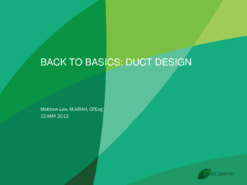
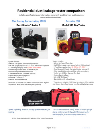
METHODOLOGY3. METHODOLOGY3.1 AIR DUCT LEAKAGE LABORATORYAs a first step towards meeting these goals and objectives, a research and testing laboratory, the Air DuctLeakage Laboratory (ADLL), was set up (Figure 1). This was done by customizing an existing buildingon the UNLV campus to suit the needs of the project. With the help of a local building contractor, somefeatures like partitions, trusses and soffits which are regularly seen in tract type homes in Las Vegas wereadded. he installation of units and ducts was done by a local HVAC contractor. The rationale was to usetypical components and standard field installation practices that are being used by HVAC contractors inLas Vegas area so that the design integrity of standard field practices could be analyzed.The basic set up was to create zones inside the laboratory space. Two independent HVAC units wereinstalled with different configurations of air distribution systems (ADS1 and ADS2) (see Figure 1). . TheHVAC units are outdoor-mounted, air-cooled, split-type heat pumps. Both air handlers are 1.5 ton singlephase Carrier units each with nominal air flow of 800 cfm. The first air handler (ADS1) is in thenorthwest corner of the building with the flex duct running along the west wall. The duct branches off inan asymmetrical fashion to four different registers from three regular sheet metal Y connections. For easeof identification numbers are designated to the registers and the Y connections as shown in Figure 1. Thesecond air handler (ADS2) is placed in the middle of the room and the duct configuration is symmetrical.The flex duct for this configuration runs on either sides of the supply plenum along the East wall. Air issupplied through four registers with just one sheet metal Y connection. The flex duct runs through a seriesof flat trusses in the framed soffits to simulate realistic duct runs in a typical attic. The soffits are ventedto the outside to simulate attic ventilation. One of the lateral surfaces of the soffit has been faced withdrywall and the other with transparent plexiglass for visual observations. The ducts in ADS2 are housedcompletely in the dropped down soffits, whereas in ADS1 they are partially open to the inside. Theformer demonstrates leakage to outside and the latter, leakage to inside. The supply plenum is placed righton the air handler. The return system is open to the inside. It has just one return grille that is ducted to thereturn plenum placed under the air handler.To improve the range of experimentation, a wide range of leakage levels can be introduced for bothconfigurations by creating holes (4.76 mm, 3/16” dia. each hole) at several locations of ductwork.Additional leaks can be introduced in both supply and return ducts to vary leakage from 1% to 25% oftotal system air flow. The detailed description of ADLL can be found in Appendix A. Owing to thesmall length of the return duct, the local leakages in the return side were not determined but were treatedas a single section and the aggregate return side leakage was determined.NCEMBT-0802155
METHODOLOGYFigure 1. Layout of the Air Duct Leakage Laboratory6NCEMBT-080215
METHODOLOGY3.2 ZONE DELTAP METHOD TO LOCATE AND QUANTIFY DUCT LEAKSA new method for locating and quantifying the total leakage and local leaks in residential air distributionsystems, Zone DeltaP, has been developed. It is based on the duct pressurization technique in which theduct system is pressurized by using a calibra
DUCT LEAKAGE MEASUREMENTS IN RESIDENTIAL BUILDINGS . FEBRUARY 2008 . Samir F. Moujaes, Ph. D., P. E. Nabil Nassif, Ph. D. Ken Teeters . . Minneapolis Duct Blaster.37 Figure 20. Screenshot of TECLOG .38 Figure 21. Flow and Pressure Readings Along With Summary Statistics Provid