Transcription
MechanicalForce GaugesMeasure tension, compressionor push/pull
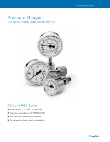
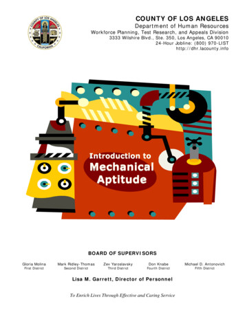
Dillon Model X Mechanical Force GaugesMeasure tension, compression and push/pull.Model X-C withcompression calibrationModel X-ST withtension calibrationModel X-C comes in ninecapacities ranging from 50 lb to25,000 lb or 50 to 10000 kg. Allfeature accuracy of 1% of fullcapacity, except the 25,000 (10000kg) capacity instruments which areaccurate to 2% of full capacity.Dillon offers the Model X-ST in sevencapacities from 100 lb to 10,000 lb or25 kg to 5000 kg. Accuracy is 1%of full range. (Note: For applicationsrequiring capacities beyond 10,000lb or 5000 kg in tension, consider theDillon Dynamometer).Load is applied against a hardenedball which rotates to maintain verticalalignment as pressure increases.The ball is held in place with a springclip or retainer. A threaded mountinghole is located opposite the loadingball in the bottom of the beam.Tension Force Gauges in capacitiesthrough 2,000 lb (1000 kg)are supplied with two rod-endconnectors. 5,000 and 10,000 lb(5000 kg) capacities are equippedwith convenient shackles and pins.Model X-C is available in pound orkilogram capacities.Calibration is available in pounds, orkilograms.Optionsn Shockless dial indicator for installations involving thesudden application or release of force. (Maximum pointercannot be supplied with shockless dial indicator.)n Maximum load pointer which remains at peak load untilmanually reset. (not available on Model X-PP)n Zero position on dial may be factory positioned at 12, 3, 6,or 9 o'clock. Standard position is at 12 o'clock.2Model X-PP withcompression/tensioncalibrationForce gauges calibrated in pushpull are available in four capacitiesin pounds ranging from 50-0-50 lbup to and including 2,500-0-2,500lb and three metric capacities from50-0-50 to 1000-0-1000 kg. Accuracyis 2% of maximum dial reading(based upon total capacity of bothcompression and tension scales).Model X-PP gauges in capacitiesup to and including 500-0-500 lb or250-0-250 kg are supplied with aset of self-aligning spherical rod-endconnectors for tension loading. Forceis applied to connectors through ahardened steel pin which must be slipfit in connector holes.2,500-0-2,500 lb and 1000-0-1000kg capacity gauges are equippedwith two shackle adapters, shacklesand pins. Shackles must be removedwhen compression load is involved.Force is then applied against shacklepins in a suitable test setup.All push-pull gauges are suppliedwith a compression-loading sphericalball fitting for compression loading.
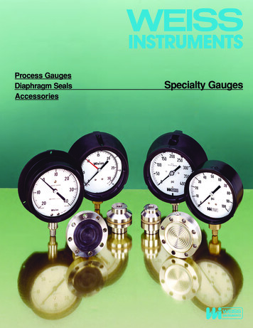
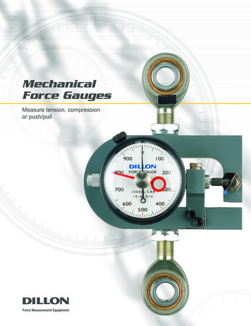
Model X Force-Gauge parts identification1113125291. Deflection beam2. Dial indicator with zeroat standard 12:00 position.13. Bezel4. Maximum load pointer (optional)5. Pressure button86. Slanted Anvil7. Dial indicator plunger8. Anvil set screw69. Mounting bracket for dial indicator10. Screws for mounting bracket11. Bezel-locking screw341012. Loading ball713. Spring retainer clipPrinciple of operationLow beam deflectionOverload ratingA D-shaped deflection beam is theheart of the Dillon Force Gauge.Machined to close tolerances, beamsare heat treated to develop optimumstrength and spring characteristics.High-strength aluminum is used inModel X instruments through 500lb (200 kg). Ranges above this arefabricated from aircraft-qualityalloy steel.When measured across the centerof top- and bottom-loading holes,the approximate beam deflection isas follows:Accidental overloads up to 30% ofcapacity can be safely sustainedwithout injury to the dial indicatoror deflection beam. All capacitiesfeature a 5:1 design safety factor.A precision dial indicator is mountedat the null point of the deflectionbeam. The indicator plunger restsagainst a slanted anvil at the openend of the beam, as shown in thephoto. Under compression loads,the two halves of the beam tend toclose. Tension force causes them tomove apart. This action pushes theplunger inward, as determined bythe slant of the anvil. Readingsproduced on the dial are in directrelation to applied load. The pointerrevolves 360 clockwise undercompression or tension forces.Push-pull gauges read half scale(180 ) clockwise in compression, andcounterclockwise, 180 from centerzero under tension loads.50 to 250-lb capacity(25 to 100 kg)0.019"500-lb capacity(200 kg)0.016"1,000-lb capacity(500 kg)0.018"2,000-lb capacity(1000 kg)0.011"5- and 10,000-lb capacity(2 and 5000 kg)0.010"25,000-lb capacity(10,000 kg)0.022"General informationn To reset zero, loosen knurledbezel-locking screw and rotatedial.n Dillon Model X Force Gauges maybe mounted horizontally, vertically,or flat.n The baked-enamel finish resistscorrosion and rust.n Operating temperatureup to 120 F.Certificate of Calibration3An official Certificate of Calibrationtraceable to NIST, dated and signed,accompanies each new or factoryserviced Dillon X Force Guage.
ABCPart No.CDTension lbPart No.Tension kg---------25 x .2530443-0176*30443-0044100 x 130443-009350 x .530443-0150* 30443-0184*30445-0034 250 x 2.5---100 x 130445-0109* 30445-0182*30445-0018500 x 530445-0026200 x 230445-0083* 30445-0091*D30276-0012 1,000 x 10---30276-0053* 30276-0061*500 x 530440-0013 2,000 x 20---30440-0054* 30440-0062*1000 x 10---5,000 x 50---2000 x 2030442-0052*---10,000 x 100---30441-0053* 30441-0061**Subject to 1/8” variation* with max hand45000 x 50
Model X-C (Compression) Force GaugePart No.ABPoundsPart No.ABCDEFGHJJ1KKilograms in. (mm) in. (mm) in. (mm) in. (mm) in. (mm) in. (mm) in. (mm) in. (mm) in. (mm) in. (mm) in. (mm)30386-003550 x 06(52.3)2.00(50.8)2.25(57.1).381/4-28 1/4-28(9.6)2.94(74.6)30386-0043100 x 1---50 x .530386-0159* )2.06(52.3)2.00(50.8)2.25(57.1).381/4-28 1/4-28(9.6)2.94(74.6)30446-0033 250 x 2.5---100 x 130446-0090* )2.06(52.3)2.00(50.8)2.25(57.1).381/4-28 1/4-28(9.6)2.94(74.6)30446-0017500 x 5---200 x 230446-0074* )2.06(52.3)2.00(50.8)2.25(57.1).381/4-28 1/4-28(9.6)2.94(74.6)30444-0019 1,000 x 10---500 x 530444-0050* )2.06(52.3)2.00(50.8)2.25(57.1).381/2-20 1/2-20(9.6)2.94(74.6)30388-0017 2,000 x 20---1000 x 1030388-0058* )2.25(57.1)2.50(63.5)2.75(69.8).381/2-20 1/2-20(9.6)3.44(87.3)30389-0016 5,000 x 50---2000 x 2030389-0057* )2.25(57.1)2.50(63.5)2.75(69.8).381/2-20 1/2-20(9.6)3.44(87.3)30423-0014 10,000 x 100---5000 x 5030423-0055* 0)2.75(69.8)3.00(76.1)3.62(91.9).757/8-14 7/8-144.50(19.0) (114.2)30449-0014 25,000 x 250---10000 x 100 6.5630449-0055* .31(84.0)3.63(92.1)3.62(91.9)1.001-14 1 1/4-12 5.50(25.4) (139.6)* with max handModel X-ST (Tension) and Model X-PP (Push-Pull) GaugesPart No.Push-Pull lbPart No.Push-Pull kgABCDEFGHJKLMNin. (mm) in. (mm) in. (mm) in. (mm) in. (mm) in. (mm) in. (mm) in. (mm) in. (mm) in. (mm) in. (mm) in. (mm) in. .0).385.004.25(9.6) (57.1).25(6.3).75(19.0).385.004.25(9.6) 6) .3).75(19.0).385.004.25(9.6) 25(57.1).50(12.7)1.31(33.2).626.945.62(15.7) 2.7)1.31(33.2).627.446.12(15.7) (155.3)1/2-2030800-0017 2,500-0-2,500 30800-0025 .9).755.441.94(19.0) 9(322.1)1.69(42.9).757.19(19.0)51.94 7/8-1/4(182.5)
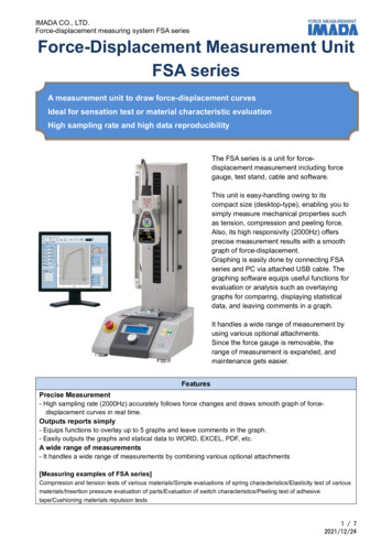
Dillon Model U Force GaugesSlim line design for added versatility.The Model U Force Gauge is an accurate ( 1% of full range) mechanicalcompression-measurement instrument. Its slim-line design has repeatedly proven valuable in installationswhere space is at a premium.The versatility of this simpleinstrument is demonstrated by thefact that it can be used as a handheld device, permanently mountedon a flat surface plate, or used intest fixtures.How the U ForceGauge WorksThe Dillon Model U Force Gaugeemploys a deflection beam machinedfrom aircraft quality alloy steel andheat treated to develop optimumstrength and spring characteristics.A precision dial indicator is mountedat the null point of this beam.2415Compression force is normallyapplied against a single pressurefitting mounted on the upper half ofthe beam. (For accurate calibration,designate the type of pressure fittingyou wish to use with the U ForceGauge. They are of four types:domed, cupped, flat, or a flat nyloninsert. Flat bottom gauges requireonly one fitting).Options6:003:009:00When load is exerted, the beammoves downward causing a slantedanvil on the free end to push againstthe indicator plunger. The indicatorreading is a direct representation ofthe applied load.Dillon offers a capacityfor every jobU Force Gauges are available formeasurement in pounds or kilograms.There are 6-pound capacities rangingfrom 25 x .25 to 5,000 x 50 lb. The 4kilogram capacities range from 10 x.1 to 500 x 5 kg.Dillon also offers high-capacitygauges with pounds capacities from500 to 5,000 lb and a metric modelwith a capacity of 500 kg. Highcapacity gauges all have flat-bottomdesign.6312:00Zero position—The zero positionon the indicator dial can be factorypositioned at 12 o'clock, 3 o'clock,6 o'clock, or 9 o'clock. The standardposition is the 6 o'clock position.Maximum pointer—Model U ForceGauges can include a maximumpointer which remains at peak loaduntil it is reset.Shockless dial indicator—Offersadded protection in applications whereforce is applied or released rapidly.Dial orientation—The dialindicator can be factory positionedat 0 (standard), 90 , 180 , 270 clockwise. Photos on this page showstandard dial orientation.Note: maximum pointer andshockless dial indicator cannot beoffered on the same unit.1. Deflection beam2. Indicator with zero at 6:00 positionCertificate of Calibration3. Pressure fittingAn official Certificate of Calibrationtraceable to NIST, dated and signed,accompanies each new or factoryserviced Dillon U Force Guage.4. Maximum pointer (optional)5. Indicator plunger6. Slanted anvil6
Low-Range Flat-Bottom Model U Force GaugePart No.PoundsABCDEFGHJKLMPart No. Kilograms in. (mm) in. (mm) in. (mm) in. (mm) in. (mm) in. (mm) in. (mm) in. (mm) in. (mm) in. (mm) in. (mm) in. (mm)30354-0017 25 x .25 30354-0066 10 x (2.4)1.67(42.4)30354-0033 100 x 1 30354-0082 50 x (2.4)1.67(42.4)30354-0058 250 x 2.5 30354-0090 100 x 2.4)1.67(42.4)Also available in newton calibrationHigh-Range Flat Bottom Model U Force GaugePart No.PoundsPart No.ABCDEFGHJNKilograms in. (mm) in. (mm) in. (mm) in. (mm) in. (mm) in. (mm) in. (mm) in. (mm) in. (mm) in. (mm)30482-0020500 x 57.2)30482-0053 1,000 x 10 30482-0079 500 x 0478-0034 5,000 x 50------4.747.94(120.1) 52.3)2.06(52.3)2.88(72.8)2.75(69.9)7
30160-0011Select the rightpressure fittings30156-0017Load is applied to the Dillon Model U Force Gaugethrough hardened pressure fittings.Replacement fittings for recessed-bottom - two fittingsFlat-bottom - one fitting30159-0014Fittings are not included. Choose fittings from the below -0015For 25 to 250 lb (10 to 100 kg) capacity gauges:Part No. 30160-0011 flat surfacePart No. 30156-0017 cupped surfacePart No. 30159-0014 domed surfacePart No. 30158-0015 nylon insertFor 500 lb, 1000 lb, and 500 kg capacity gauges:Part No. 30483-0011 domed surfacePart No. 30378-0019 cupped surfacePart No. 30484-0010 flat surfaceFor 5,000 lb capacity gauges:Part No. 30434-0011 domed surface pressure fittingPart No. 30125-0015 cupped surface pressure fittingPart No. 30475-0011 flat surface30484-0010AUTHORIZED DISTRIBUTORSDILLON USADILLON UKAsk the experts. Dillon distributorsoffer complete service capabilitiesfrom application assistance tosales and product support. Theirexperienced representatives are themost knowledgeable experts that youwill find in the force measurementindustry. We recommend that youconsult these capable specialists forall of your measuring needs.1000 Armstrong DriveFairmont, MN 56031Foundry Lane, Smethwick,West Midlands B66 2LPToll-Free: (800) 368-2031Phone: (507) 238-8796Fax: (507) 238-8258Phone: 44 (0) 845 246 6717Fax: 44 (0) 845 246 6718Email: lon-force.co.uk30475-0011A division of Avery Weigh-Tronix, LLCDillon is part of Avery Weigh-Tronix. Avery Weigh-Tronix is a trademark of the Illinois Tool Works group of companies whose ultimateparent company is Illinois Tool Works Inc (“Illinois Tool Works”). Copyright 2018 Illinois Tool Works. All rights reserved. This publication1/18is issued to provide outline information only and may not be regarded as a representation relating to the products or services concerned.mech force gauges L 08595-0012.inddThis publication was correct at the time of going to print, however Avery Weigh-Tronix reserves the right to alter without notice the08595-0012specification, design, price or conditions of supply of any product or service at any time.
connectors for tension loading. Force is applied to connectors through a hardened steel pin which must be slip fit in connector holes. 2,500-0-2,500 lb and 1000-0-1000 kg capacity gauges are equipped with two shackle adapters, shackles and pins. Shackles must be removed when compression load is involved. Force is then applied against shackle