Transcription
Fundamentals of Mechanical Engineering
THIS BOOK WAS DEVELOPED BY IDC TECHNOLOGIESWHO ARE WE?IDC Technologies is internationally acknowledged as the premier provider of practical, technical trainingfor engineers and technicians.We specialize in the fields of electrical systems, industrial data communications, telecommunications,automation and control, mechanical engineering, chemical and civil engineering, and are continuallyadding to our portfolio of over 60 different workshops. Our instructors are highly respected in their fieldsof expertise and in the last ten years have trained over 200,000 engineers, scientists and technicians.With offices conveniently located worldwide, IDC Technologies has an enthusiastic team of professionalengineers, technicians and support staff who are committed to providing the highest level of training andconsultancy.TECHNICAL WORKSHOPSTRAINING THAT WORKSWe deliver engineering and technology training that will maximize your business goals. In today’scompetitive environment, you require training that will help you and your organization to achieve its goalsand produce a large return on investment. With our ‘training that works’ objective you and yourorganization will: Get job-related skills that you need to achieve your business goals Improve the operation and design of your equipment and plant Improve your troubleshooting abilities Sharpen your competitive edge Boost morale and retain valuable staff Save time and moneyEXPERT INSTRUCTORSWe search the world for good quality instructors who have three outstanding attributes:1. Expert knowledge and experience – of the course topic2. Superb training abilities – to ensure the know-how is transferred effectively and quickly to you ina practical, hands-on way3. Listening skills – they listen carefully to the needs of the participants and want to ensure that youbenefit from the experience.Each and every instructor is evaluated by the delegates and we assess the presentation after every class toensure that the instructor stays on track in presenting outstanding courses.HANDS-ON APPROACH TO TRAININGAll IDC Technologies workshops include practical, hands-on sessions where the delegates are given theopportunity to apply in practice the theory they have learnt.REFERENCE MATERIALSA fully illustrated workshop book with hundreds of pages of tables, charts, figures and handy hints, plusconsiderable reference material is provided FREE of charge to each delegate.ACCREDITATION AND CONTINUING EDUCATIONSatisfactory completion of all IDC workshops satisfies the requirements of the International Associationfor Continuing Education and Training for the award of 1.4 Continuing Education Units.IDC workshops also satisfy criteria for Continuing Professional Development according to therequirements of the Institution of Electrical Engineers and Institution of Measurement and Control in theUK, Institution of Engineers in Australia, Institution of Engineers New Zealand, and others.
CERTIFICATE OF ATTENDANCEEach delegate receives a Certificate of Attendance documenting their experience.100% MONEY BACK GUARANTEEIDC Technologies’ engineers have put considerable time and experience into ensuring that you gainmaximum value from each workshop. If by lunchtime on the first day you decide that the workshop is notappropriate for your requirements, please let us know so that we can arrange a 100% refund of your fee.ONSITE WORKSHOPSAll IDC Technologies Training Workshops are available on an on-site basis, presented at the venue ofyour choice, saving delegates travel time and expenses, thus providing your company with even greatersavings.OFFICE LOCATIONSAUSTRALIA CANADA INDIA IRELAND MALAYSIA NEW ZEALAND POLAND SINGAPORE SOUTH AFRICA UNITED KINGDOM UNITED STATESidc@idc-online.comwww.idc-online.comVisit our website for FREE Pocket GuidesIDC Technologies produce a set of 6 Pocket Guides used bythousands of engineers and technicians worldwide.Vol. 1 – ELECTRONICSVol. 4 – INSTRUMENTATIONVol. 2 – ELECTRICALVol. 5 – FORMULAE & CONVERSIONSVol. 3 – COMMUNICATIONS Vol. 6 – INDUSTRIAL AUTOMATIONTo download a FREE copy of these internationally best selling pocket guides go to:www.idc-online.com/downloads/
PresentsFundamentals of MechanicalEngineeringRevision 5Website: www.idc-online.comE-mail: idc@idc-online.com
IDC Technologies Pty LtdPO Box 1093, West Perth, Western Australia 6872Offices in Australia, New Zealand, Singapore, United Kingdom, Ireland, Malaysia, Poland, United States ofAmerica, Canada, South Africa and IndiaCopyright IDC Technologies 2009. All rights reserved.First published 2009All rights to this publication, associated software and workshop are reserved. No part of this publicationmay be reproduced, stored in a retrieval system or transmitted in any form or by any means electronic,mechanical, photocopying, recording or otherwise without the prior written permission of the publisher. Allenquiries should be made to the publisher at the address above.ISBN: 978-1-921007-07-1DisclaimerWhilst all reasonable care has been taken to ensure that the descriptions, opinions, programs, listings,software and diagrams are accurate and workable, IDC Technologies do not accept any legal responsibilityor liability to any person, organization or other entity for any direct loss, consequential loss or damage,however caused, that may be suffered as a result of the use of this publication or the associated workshopand software.In case of any uncertainty, we recommend that you contact IDC Technologies for clarification or assistance.TrademarksAll logos and trademarks belong to, and are copyrighted to, their companies respectively.AcknowledgementsIDC Technologies expresses its sincere thanks to all those engineers and technicians on our trainingworkshops who freely made available their expertise in preparing this manual.
Contents12Basics of Mechanical Engineering11.11.21.31.41.512569IntroductionBasic conceptsUnits of engineering quantitiesFrictionSummaryMechanical 3233343435363738383839Types of lines and letters used in drawingsTypes of linesLettering in the drawingsSummary for Section AProjectionsWhat is projection?Pictorial projectionsConcept of cutting plane and sectional viewsSummary of Section BDimensioningDifferent systems of dimensioningDimensioning practicesSummary of Section CAssembly drawingsSummary of Section DWelded jointsTypes of welded jointsSummary of Section EBolt, nut and screw fastenersIntroductionSummary of Section FKeys, keyways and keyed assembliesTypes of keysSummary of Section GTolerance, limits and fitsConcept of toleranceConcept of limitsConcept of fitSummary of Section HThe role of CAD and CAMUse of computers for preparation of drawingsCAD softwareComputer Aided Manufacturing (CAM)
2.25J2.262.2734639393940Engineering 485255606465Mechanical properties of materialsProcessing of metals and alloysStress and strain in metalsNormal stress and shear stressTensile and hardness testingStress and strain diagramAlloy production and propertiesFracture of metalsCorrosion types and controlSummaryMechanical Design4.14.24.34.44.54.64.74.84.95Summary of Section IOffice practiceDrawing number and part nameSummary of Section JIntroductionCodes and standardsDesign considerationsFactory of safetyMechanical componentsFasteners/screwed jointsFastener failureCompression membersSummary676770707677105111115120Mechanical Engineering Codes and 8129Need for standardizationOverview of standardsBenefits of standardizationMechanical engineering standardsISO 6.56.66.7131134135137139142146Foundry processingHeat treatmentHot working of metalsCold working of metalsPressingNumerical controlSawing
6.86.96.106.116.126.136.14789BroachingShapers and shapingWeldingBrazingComputer-aided manufacturingManufacturing processes in oil and gas industrySummary146147147148149150150Mechanical 170170172176178180181186187192Sensors and actuatorsDifferential transformersVelocity and motionFluid pressure measurementLiquid flow measurementLiquid level measurementTemperature measurementLight sensorsSelection of sensorsPneumatics and hydraulicsControl valvesCylindersElectrical actuationElectrical drivesElectrical machinesGear motorsControl systemsSummaryFluid 228229PumpsCompressorsTurbinesFlow in pipesThermodynamicsReversibilitySummaryMaintenance of 6244The need for maintenanceTypes of maintenanceMaintenance strategiesFailureHow to select your maintenance planPredictive maintenance techniquesSummary
10Theory of Heat 49251258261263264Heat basicsHeat transferLaws of ThermodynamicsThermal cyclesHeat cyclesHeat pumpsAir conditioningSummaryExercises265Answers309
1Basics of Mechanical EngineeringMechanical Engineering, as its name suggests, deals with the mechanics of operation of mechanicalsystems. This is the branch of engineering which includes design, analysis, testing, manufacturingand maintenance of mechanical systems. The mechanical engineer may design a component, amachine, a system or a process. Mechanical engineers will analyze their design using the principlesof motion, energy, and force to ensure the product functions safely, efficiently, reliably, and can bemanufactured at a competitive cost.Learning objectives 1.1Basic conceptsUnits for engineering quantitiesFriction and its importanceIntroductionMechanical engineering plays a dominant role in enhancing safety, economic vitality, enjoymentand overall quality of life throughout the world. Mechanical engineers are concerned with theprinciples of force, energy and motion.Mechanical engineering is a diverse subject that derives its breadth from the need to design andmanufacture everything from small individual parts and devices (e.g. microscale sensors and inkjetprinter nozzles) to large systems (e.g. spacecraft and machine tools). The role of a mechanicalengineer is to take a product from an idea to the marketplace. In order to accomplish this, a broadrange of skills are needed. Since these skills are required for virtually everything that is made,mechanical engineering is perhaps the broadest and most diverse of engineering disciplines.Mechanical engineers play a central role in such industries as automotive (from the car chassis toits every subsystem — engine, transmission, sensors); aerospace (airplanes, aircraft engines,control systems for airplanes and spacecraft); biotechnology (implants, prosthetic devices, fluidicsystems for pharmaceutical industries); computers and electronics (disk drives, printers, coolingsystems, semiconductor tools); microelectromechanical systems (MEMS) (sensors, actuators,micropower generation); energy conversion (gas turbines, wind turbines, solar energy, fuel cells);environmental control (HVAC, air-conditioning, refrigeration, compressors); automation (robots,data and image acquisition, recognition, control) and manufacturing (machining, machine tools,prototyping, micro fabrication).
2 Fundamentals of Mechanical EngineeringThe main areas of study in this branch are: Materials Solid and fluid mechanics Thermodynamics Heat transfer Control, instrumentation Specialized mechanical engineering subjects include biomechanics, cartilage-tissueengineering, energy conversion, laser-assisted materials processing, combustion,MEMS, micro fluidic devices, fracture mechanics, nanomechanics, mechanisms,micropower generation, tribology (friction and wear) and vibrations.1.2Basic concepts1.2.1ForceA foundation concepts in physics, a force may be thought of as any influence which tends tochange the motion of an object. A force can be described as the push or pull upon an objectresulting from the object's interaction with another object. Whenever there is an interactionbetween two objects, there is a force upon each of the objects. When the interaction ceases, the twoobjects no longer experience the force. Forces only exist as a result of an interaction.There are four fundamental forces in the universe: the gravity force, the nuclear weak force, theelectromagnetic force, and the nuclear strong force in ascending order of strength. In mechanics,forces are seen as the causes of linear motion, whereas the cause of rotational motion is called atorque. The action of forces in causing motion is described by Newton's Laws.Force is a quantity which is measured using the standard metric unit called the Newton. A Newtonis abbreviated by a "N". To say "10.0 N" means 10 Newtons of force. One Newton is the amount offorce required to give a 1 kg mass an acceleration of 1 m/s2.Force mass x accelerationF m x a 1 kg x 1 m / s2A force is a vector quantity — it has both magnitude and direction. To fully describe the forceacting upon an object, you must describe both the magnitude (size or numerical value) and thedirection. Thus, 10 Newtons is not a full description of the force acting upon an object. In contrast,10 Newtons downwards is a complete description of the force acting upon an object; both themagnitude (10 Newtons) and the direction (downwards) are given.A torque is a special form of force that turns an axle in a given direction. It is sometimes called arotational force. You can create a torque by pushing on a rod or lever that rotates an axle. Likewise,a torque on an axle can result in a linear force at a distance from the center of the axle.Torque equals force multiplied by moment arm. Pushing on a rod that rotates an axle can create atorque on that axle. Likewise, a torque on an axle can result in a linear force at a radius from thecenter.The relationship between torque and force is:T FRorF T/RwhereT is the torque in newton-metersF is the force (Newtons)R is the radius or distance from the center to the edge (meters)
Mechanical Engineering Basics3R is also sometimes called the moment arm. The force, F, is applied perpendicular to the radius,lever or moment arm.1.2.2WorkWork refers to an activity involving a force and movement in the direction of the force.A work is done on an object when the force acts on it in the direction of motion or has componentin the direction of motion.In order to accomplish work on an object there must be a force exerted on the object and it mustmove in the direction of the force.Work Force x distance moved in direction of forceWork is measured in joules (J ). The formula for this is:J NxmWhere force is measured in Newtons and distance in meters.For a constant force F which moves an object in a straight line from x1 to x2, the work done by theforceWork force x (x2-x1)Mathematically, work can be expressed by the following equation:W F x d x cos Θwhere F is the force, d is the displacement, and the angle (theta) is defined as the angle between theforce and the displacement vector. Perhaps the most difficult aspect of the above equation is theangle "theta." Theta is defined as the angle between the force and the displacement. A force acts from the right on an object and it is displaced to the right. In such aninstance, the force vector and the displacement vector are in the same direction. Thus,the angle between F and d is 0 degrees.dΘ 0 degreesF A force acts from the left on an object and it is displaced to the right. In such aninstance, the force vector and the displacement vector are in the opposite direction.Thus, the angle between F and d is 180 degrees.dΘ 180 degreesF A force acts upward on an object as it is displaced to the right. In such an instance, theforce vector and the displacement vector are at right angles to each other. Thus, theangle between F and d is 90 degrees.dFΘ 90 degreesFor the more general case of a variable force F(x) which is a function of x, the work is still the areaunder the force curve, and the work expression becomes an integral.
4 Fundamentals of Mechanical EngineeringWork is not done when there is no motion or when the force is perpendicular to the motion.Let us apply the work equation to determine the amount of work done by the applied force in eachof the three situations described below.Diagram A Answer:W (100 N) x (5 m) x cos (0 degrees) 500 JThe force and the displacement are given in the problem statement. It is said (or shown or implied)that the force and the displacement are both to the right. Since F and d are in the same direction, theangle is 0 degrees.Diagram B Answer:W (100 N) x (5 m) x cos (30 degrees) 433 JThe force and the displacement are given in the problem statement. It is said that the displacementis to the right. It shows that the force is 30 degrees above the horizontal. Thus, the angle between Fand d is 30 degrees.Diagram C Answer:W (147 N) x (5 m) x cos (0 degrees) 735 J1.2.3EnergyEnergy is the capacity for doing work. You must have energy to accomplish work – it is like the"currency" for performing work. In the process of doing work, the object which is doing the workexchanges energy with the object upon which the work is done. When the work is done on theobject it gains energy. The energy acquired by the objects upon which work is done is known asmechanical energy.Mechanical energy is the energy which is possessed by an object due to its motion or due to itsposition. Mechanical energy can be either kinetic energy (energy of motion) or potential energy(stored energy of position). Objects have mechanical energy if they are in motion and/or if they areat some position relative to a zero potential energy position.Mechanical energy Kinetic energy Potential energyPotential Energy PE mass of the object x acceleration of gravity x height of the object
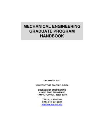
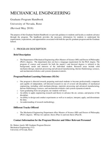
Mechanical Engineering Basics5PE m x g x hg represents the acceleration of gravity (9.8 m/s/s on Earth)Kinetic Energy is depend on two variables: the mass and the speedThe following equation is used to represent the kinetic energy (KE) of an object.KE 1/ 2 x m x v 21.2.4PowerPower is the rate at which work is done. It is the work/time ratio. Mathematically, it is computedusing the following equation.Power work / time (force x displacement) / timeThe standard metric unit of power is the Watt. As is implied by the equation for power, a unit ofpower is equivalent to a unit of work divided by a unit of time. Thus, a Watt is equivalent to aJoule/second. For historical reasons, the term ‘horsepower’ is occasionally used to describe thepower delivered by a machine. One horsepower is equivalent to approximately 750 Watts.Most machines are designed and built to do work on objects. All machines are typically describedby a power rating. The power rating indicates the rate at which that machine can do work uponother objects. Thus, the power of a machine is the work/time ratio for that particular machine. Thepower rating relates to how rapidly the engine can accelerate the car.1.3Units of engineering quantitiesTable 1.1 gives the most common units of engineering quantities that you will come across.Figure 1.1 shows a representation of the linkage of basic mechanical units.Table 1.1Units of engineering quantitiesLength (L)Time (T)Mass (M)Velocity (L/T)Acceleration (L/T2 )Force (M L/ T2)Work (M L2/ T2)Energy (M L2/ T2)Power (M L2/ T3)SI unitsMeter mSecond sKilogram kgm/sm/ s2kg m / s2 Newton NN m J joulejouleJ / s W wattsUS commonFoot ftSecond sSlugft/sft/ s2slug ft/ s2 pound lblb ft ft lbft lbft lb/s
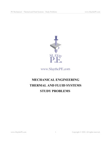
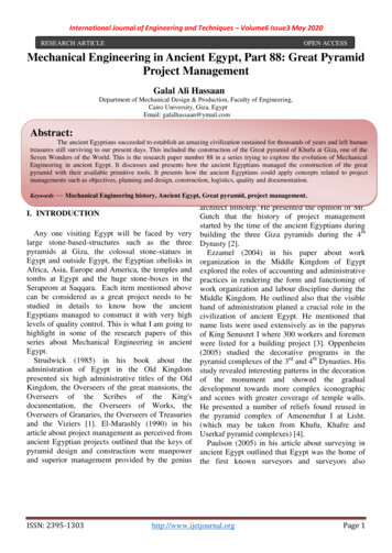
6 Fundamentals of Mechanical EngineeringDivided byLength LgivesTime TSpeed L / TWhich with direction becomesMass MVelocityAccelerationL / T2the rate ofTimeschange of velocitygivesForce M L / T2timesPowerleverarm23ML /TtimesmovedTorqueM L2 / T2distancerate of doing workWorkM L 2 / T2EnergyM L2 / T2Figure 1.1Basic Mechanical units1.4FrictionFriction is a force that is created whenever two surfaces move or try to move across each other.Friction always opposes the motion or attempted motion of one surface across another surface.Friction is dependant on the texture of both surfaces and the amount of contact force pushing thetwo surfaces together.In a machine, friction reduces the ratio of output to input. An automobile, for instance, uses onequarter of its energy on reducing friction. Yet it is also friction in the tires that allows the car to stayon the road, and friction in the clutch that makes it possible to drive at all. From matches tomachines to molecular structures, friction is one of the most significant phenomena in the physicalworld.There are advantages and disadvantages of friction. Since friction is a resistance force that slowsdown or prevents motion, it is necessary in many applications to prevent slipping or sliding. But itcan also be a nuisance because it can hinder motion and cause the need for expending energy. Agood compromise is necessary to get just enough friction.Disadvantages of friction: makes movement difficult machine parts get overheated wastes energy any device that has moving parts can wear out rapidly due to friction. Lubrication isused not only to allow parts to move easier but also to prevent them from wearing out.The force of friction is a force that resists motion when two objects are in contact. If we look at thesurfaces (Figure 1.2) of all objects, there are tiny bumps and ridges. Those microscopic peaks andvalleys catch on one another when two objects are moving past each other.
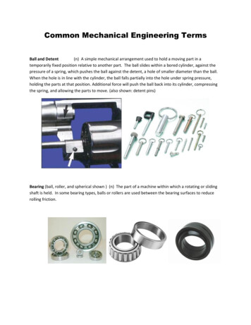
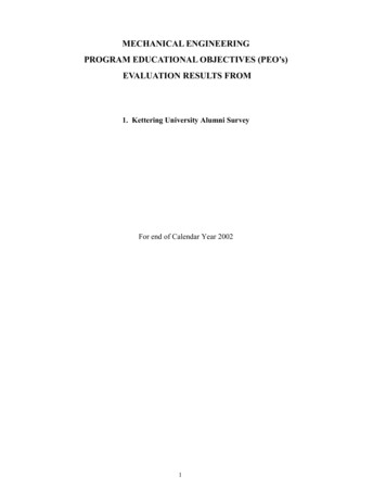
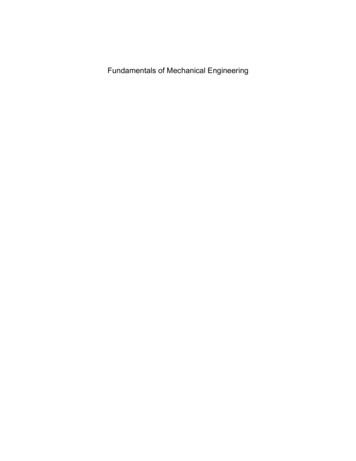
Mechanical Engineering Basics7Figure 1.2Typical surfaceThere are two types of friction Static KineticIf we try to slide two objects past each other, a small amount of force will result in no motion. Theforce of friction is greater than the applied force. This is static friction. (Figure 1.3) If we apply alittle more force, the object ‘breaks free’ and slides, although we still need to apply force to keepsthe object sliding. This is kinetic friction (Figure 1.4). We need not apply quite as much force tokeep the object sliding as we originally needed to break free from the static friction.Figure 1.3Static frictionFigure 1.4Kinetic frictionFigure 1.5 shows the relationship between applied force and frictional force.
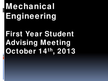
8 Fundamentals of Mechanical EngineeringFigure 1.5Relationship between applied and frictional forceLet’s examine the relationship between these two forces and the applied force that creates them.Figure 1.5 shows static frictional force increasing to a maximum with the application of a forcethen dropping off sharply to a lesser value (kinetic friction) once the object starts moving. We canconclude few points from this graph such as those listed below.Static friction: Static friction fs is proportional to Fn (surface normal force) It is independent of area It reaches a maximum value (which depends on the surface materials) in preventingmotion between surfaces, and then drops to the lower value of sliding friction as theobject begins to move.Kinetic friction: Kinetic friction fk is proportional to Fn It is also independent of area and speed of surfaces It is always less than static friction fk fs (meaning it’s easier to push an object onceit’s moving)Since friction is proportional to the force pressing the surfaces together (Fn)f α Fnwhich means that,f / Fn constantThis constant is known as coefficient of friction: μ (the Greek letter ‘mu’). Thus we can write theequation as:f μ x FnSince static friction and kinetic friction are different, there is a μ for each one:μs coefficient of static frictionμk coefficient of kinetic frictionTable 1.2 shows some common values of coefficients of kinetic and static friction.Static friction fs μs Fn
Mechanical Engineering BasicsKinetic fk9 μkFnNote that static friction is expressed as an inequality in the above equation. This is because it variesfrom zero to a maximum. At the maximum value, and only at the maximum value (just before theobject moves), the static frictional force is exactly equal to μsFn, orfs max μs FnCoefficient of friction μ f / FnTable 1.2Some common values of coefficients of kinetic and static frictionµ (static)µ (kinetic)μsμkSteel on steel0.740.57Glass on glass0.940.40Metal on Metal(lubricated)0.150.06Ice on ice0.100.03Teflon on Teflon0.040.04Tire on concrete1.000.80Tire on wet road0.600.40Tire on snow0.300.20SurfacesThese values are approximate.1.5SummaryMechanical Engineering deals with mechanics of operation on different systems. The variousfunctions that fall within the scope of this branch are designing, manufacturing and maintenance.For this purpose it uses laws of physics and applies them to analyze their performance.Friction is a force which is created when two surfaces move across each other. It plays veryimportant role in some situations like walking, writing, etc. where you could not do without theforce of friction. In some cases friction is less required, so compromise is required.
10 Fundamentals of Mechanical Engineering
Mechanical Engineering, as its name suggests, deals with the mechanics of operation of mechanical systems. This is the branch of engineering which includes design, analysis, testing, manufacturing and maintenance of mechanical systems. The mechanical engineer