Transcription
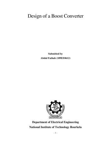
Flyback ConverterProject report submitted in partial fulfillment of the requirements ofBachelor of TechnologyBy,Anurag Gupta120070029Guide: Professor Mukul C. ChandorkarDepartment of Electrical EngineeringIndian Institute of Technology, BombayApril, 2016
Table of ContentsTable of Contents . 21Introduction . 41.1Buck-Boost converter . 41.1.11.2Flyback converter . 51.2.123Principle of operation . 5Principle of operation . 5Flyback converter for Modular Multilevel converter . 62.1Rating. 72.2TNY279 Functional description . 72.3TNY279 Operation . 82.4Feedback circuit . 92.5Current limit state machine . 102.6Schematic . 112.7PCB layout . 132.8Testing . 142.9Application . 172.9.1Pre-charging of module capacitors . 182.9.2Design modification . 202.9.3Challenges . 21Flyback converter for powering Nixie tubes . 223.1Nixie tubes . 223.2Rating. 223.3Multi-output flyback converter . 223.3.1Motivation. 223.3.2Design specification . 223.3.3Transformer design . 253.3.4Results . 273.4USB powered flyback converter . 283.4.1Design. 293.4.2Transformer design . 29
3.4.33.54Results . 30Conclusion . 32Reference . 33
1 IntroductionFlyback converter (Figure 1) is a dc-dc converter topology derived from buck-boost converter(Figure 2) with inductor split up to form a transformer for galvanic isolation between inputand output. Section 1.1 describes the working of buck-boost converter followed bydescription of flyback converter in Section 1.2.Figure 1: Flyback converterFigure 2: Buck-Boost converter1.1 Buck-Boost converterA buck-boost converter has an output voltage that is either greater than or less than inputvoltage depending on duty cycle of switching pulse. Its voltage gain expression is given by𝑉𝑜𝑢𝑡𝐷 𝑉𝑖𝑛1 𝐷𝑉𝑜𝑢𝑡 : 𝑂𝑢𝑡𝑝𝑢𝑡 𝑣𝑜𝑙𝑡𝑎𝑔𝑒 𝑎𝑐𝑟𝑜𝑠𝑠 𝑐𝑎𝑝𝑎𝑐𝑖𝑡𝑜𝑟 𝐶1𝑉𝑖𝑛 : 𝐼𝑛𝑝𝑢𝑡 𝑠𝑜𝑢𝑟𝑐𝑒 𝑣𝑜𝑙𝑡𝑎𝑔𝑒 𝑉1𝐷: 𝑑𝑢𝑡𝑦 𝑐𝑦𝑐𝑙𝑒 𝑜𝑓 𝑠𝑤𝑖𝑡𝑐ℎ𝑖𝑛𝑔 𝑝𝑢𝑙𝑠𝑒
1.1.1 Principle of operationLet us assume that buck-boost converter is operating in continuous conduction mode (CCM)for analysis. During steady state, voltage Vout appears across the capacitor (C1) and a non-zeroaverage current flows through the inductor (L1). The basic operation of buck-boost convertercan be understood by analyzing the two states of switch (Q1).When the switch (Q1) turns ON, input voltage is directly connected to inductor L1, ignoringthe on state resistance of switch, and diode D1 gets reverse biased. This leads to rise in currentthrough inductor governed by expression𝑑𝑖𝑉 𝐿 ( )𝑑𝑡𝑉: 𝑉𝑜𝑙𝑡𝑎𝑔𝑒 𝑎𝑐𝑟𝑜𝑠𝑠 𝑖𝑛𝑑𝑢𝑐𝑡𝑜𝑟𝐿: 𝑉𝑎𝑙𝑢𝑒 𝑜𝑓 𝑖𝑛𝑑𝑢𝑐𝑡𝑎𝑛𝑐𝑒𝑖: 𝐼𝑛𝑑𝑢𝑐𝑡𝑜𝑟 𝑐𝑢𝑟𝑟𝑒𝑛𝑡When the switch (Q1) turns OFF, current through inductor cannot immediately die down tozero, hence, diode (D1) starts conducting due to Faraday’s law of electromagnetic inductionproviding a path for inductor (L1) to charge the output capacitor (C1).To derive voltage gain expression, we can use the condition that average voltage acrossinductor should be equal to zero (or else the inductor will burn). During ON state, 𝑉𝐿1 𝑉𝑖𝑛and during OFF state, 𝑉𝐿1 𝑉𝑜𝑢𝑡 . Applying average voltage criteria, we get𝑉𝑖𝑛 𝐷 𝑇 𝑉𝑜𝑢𝑡 (1 𝐷) 𝑇 0𝑇: 𝑇𝑖𝑚𝑒 𝑝𝑒𝑟𝑖𝑜𝑑 𝑜𝑓 𝑠𝑤𝑖𝑡𝑐ℎ𝑖𝑛𝑔 𝑝𝑢𝑙𝑠𝑒 𝑉𝑜𝑢𝑡𝐷 𝑉𝑖𝑛1 𝐷1.2 Flyback converterAs explained earlier, flyback converter is obtained by replacing inductor with transformer ina buck-boost converter. Corresponding voltage gain expression for flyback converter is𝑉𝑜𝑢𝑡 𝑁2𝐷 𝑉𝑖𝑛𝑁1 1 𝐷𝑁1 : 𝑁𝑢𝑚𝑏𝑒𝑟 𝑜𝑓 𝑡𝑢𝑟𝑛𝑠 𝑜𝑛 𝑡ℎ𝑒 𝑝𝑟𝑖𝑚𝑎𝑟𝑦 𝑠𝑖𝑑𝑒 𝑜𝑓 𝑡𝑟𝑎𝑛𝑠𝑓𝑜𝑟𝑚𝑒𝑟𝑁2 : 𝑁𝑢𝑚𝑏𝑒𝑟 𝑜𝑓 𝑡𝑢𝑟𝑛𝑠 𝑜𝑛 𝑡ℎ𝑒 𝑠𝑒𝑐𝑜𝑛𝑑𝑎𝑟𝑦 𝑠𝑖𝑑𝑒 𝑜𝑓 𝑡𝑟𝑎𝑛𝑠𝑓𝑜𝑟𝑚𝑒𝑟1.2.1 Principle of operationWe can analyze the two states of switch (Q1) for deriving the voltage gain expression in amanner similar to buck-boost converter.When the switch Q1 turns ON, input voltage appears across the primary side of transformer,thereby, increasing the energy stored in magnetizing inductance 𝐿𝑚 of transformer. Because
of the shown dot polarities in Figure 1, negative voltage appears across the diode D1 and itdoes not conducts. During this state, capacitor (C1) satiates the current demand of load.When the switch Q1 turns OFF, current stored in Lm cannot instantaneously die down to zero.Hence, diode (D1) starts conducting because of the Faraday’s law of electromagneticinduction and transfer of energy from inductor to output capacitor (C1) takes place.Figure 3 illustrates the voltage and current waveform for ON and OFF state of switch (Q1). 𝐼𝑝in the plot represents peak value of current through primary side of transformer (T1).Figure 3: Primary voltage, primary current, secondary current and output voltage waveform forPWM switching of flyback converterTo derive voltage gain expression, we can apply average voltage criteria on the primary sideof transformer (T1) to get𝑉𝑖𝑛 𝐷 𝑇 𝑉𝑜𝑢𝑡 𝑁1 (1 𝐷) 𝑇 0𝑁2𝑉𝑜𝑢𝑡 𝑁2𝐷 𝑉𝑖𝑛𝑁1 1 𝐷2 Flyback converter for Modular Multilevel converterDuring first part of the project, a flyback converter which takes rectified input from an ACpower supply and produces a regulated output voltage was designed as shown in Figure 4. Afull bridge rectifier followed by a smoothing capacitor was used to obtain unregulated DCsupply for the flyback converter. Further, a transformer with turn ratio of 10:1, designed byWurth Electronik, and TNY279 switch plus controller IC from Power Integration was used forgalvanic isolation and output regulation respectively. Section 2.1 specifies the rating of flyback
converter followed by functional description and operation of TNY279 in Section 2.2 andSection 2.3 respectively. Design of feedback loop is discussed in Section 2.4 followed by tersedescription of current limit state machine feature of TNY279 switch in Section 2.5. Towardthe end, Section 2.6 and 2.7 covers the schematic of implemented design and its PCB layoutin Eagle.Figure 4: Flyback converter with TNY279 controller IC2.1 RatingInput: 85-265 VAC, 3.15 A.Output: 15 V, 1 A.2.2 TNY279 Functional descriptionFigure 5 and Figure 6 shows the package and functional block diagram of TNY279 controllerIC used for the design of flyback converter. Pin EN/UV, BP/M, D and S representsenable/under-voltage, bypass/multifunction, drain and source respectively.Figure 5: TNY279 package (Source: Power Integrations)
Figure 6: TNY279 functional block diagram (Source: Power Integrations)During ON state, current flows from D to S. BP/M is used to decouple internal power supplyand to decide global limiting value of current from drain to source by appropriate choice ofcapacitor between BP/M and S. An internal current limit state machine adaptively adjusts thelocal current limit for different loads. EN/UV pin decides the state of switch based on feedbackfrom the output voltage. It can also be used to detect under-voltage on the input side andshut down the MOSFET.2.3 TNY279 OperationDuring normal operation, input circuitry at EN/UV consists of a low impedance sourcefollower set at 1.2 V. If current through this terminal exceeds the threshold value of 115 µA,a logic 1 is generated at the output of this circuitry otherwise a logic 0 is generated. Based onthe output of this logic, generated at the rising edge of internally generated 132 kHz signal,state of the switch is controlled. If logic 1 is sampled on the rising edge, MOSFET is turned offotherwise it’s turned on. During the cycle when MOSFET is turned on, drain current keepsincreasing and MOSFET is turned off as soon as this currents reaches the drain-source currentlimit as shown in Figure 7. Note that this current limit is updated by current limit statemachine based on previous cycles and is explained later.
Figure 7: TNY279 switching waveform (Source: Power Integrations)2.4 Feedback circuitUnlike PWM mode, TNY279 uses on/off method to regulate output voltage using externalfeedback circuitry. In a typical implementation, reverse breakdown voltage of zenerconnected in series with optocoupler LED decides the regulated output voltage as shown inFigure 8. When output voltage exceeds the target regulated value, LED starts to conduct andoptocoupler pulls the EN/UV pin to zero leading to turning off of switch. To set a regulatedoutput voltage of 15 V, zener diode (ZD1) with reverse breakdown voltage of 15 V was chosenfor the design. Resistance (R3) precludes damage to optocoupler by circumscribing thecurrent flowing through LED.Figure 8: Feedback circuit for TNY279
2.5 Current limit state machineThe current limit state machine reduces the current limit – for comparison with drain currentwhen MOSFET is in on state – when output is connected to light load. This increases thefrequency of switching and allays the associated audible noise due to magnetostrictionphenomenon in transformer. The state machines observes the past switching cycles ofMOSFET to determine the load condition and updates current limit in discrete steps. Figure 9and Figure 10 represents the state machine adaptation to different load conditions.Figure 9: Variation in drain current limit for moderately heavy load (Source: Power Integrations)Figure 10: Variation in drain current limit for very light load (Source: Power Integrations)
2.6 SchematicEagle 7.3 was used to design schematic (Fig. 8) for designed flyback converter.Figure 11: Eagle schematic layout for flyback converterOverall schematic can be understood by understanding its subparts as illustrated in Figure 12:Full bridge rectifier followed by pi filter - Figure 14. Subpart corresponding to Figure 12represents a full bridge rectifier followed by pi filter to generate unregulated DC supply. F1, afuse of rating 3.15 𝐴, breaks supply to circuit in the event of a fault. LED1 is meant to indicateon/off state of input. IN4007, with rating of 700 V RMS voltage, was chosen for AC rectificationkeeping in mind the maximum voltage across diodes.Figure 12: Full bridge rectifier followed by pi filter
Figure 13 represents the snubber circuit on the primary side of transformer to prevent voltagespike, during transition of states. Use of zener clamp and parallel RC optimizes both EMI andenergy efficiency.Figure 13: Snubber circuit for primary windingRemaining subpart of the schematic represents a DC-DC flyback converter topology as shownin Figure 14. Additional circuitry like 3.6 MΩ resistance facilitates under voltage protection;additional bias winding on transformer provides overvoltage protection in the event of openfeedback loop faults; indicator LED indicates the state of output.Figure 14: DC-DC flyback converter
In this project, transformer ratio of 10:1 is used for designing a flyback converter with 15 Vregulated output and 1 𝐴 current rating. Therefore, reverse breakdown voltage of zenerdiode (in this case 15 V), connected between optocoupler input and output voltage, plus theoptocoupler LED forward drop should be such that when the output exceeds 15 V, currentshould flow in the LED of optocoupler. This would result in current greater than 115 µA tosink from EN/UV pin of TNY279 switch, turning the MOSFET off. Note that transformer ratioof 10:1 was chosen in accordance with zener clamping circuit. As per design criteria of zenerclamping circuit, if clamping voltage of zener diode is around 150 V, output voltage of 12 Vwhen reflected on primary would be close to but less than 150 V.2.7 PCB layoutEagle 7.3 was used for designing PCB layout as shown in Fig. 12. Basic considerations whiledesigning the layout show in Figure 15 were as follows: Minimizing distance between positive and negative terminals of AC source to reducestray inductance.Minimum separation of 2 cm between ground plane of input and output.Large distance between input and output connector for safety.Figure 15: Board layout of the flyback converter
2.8 TestingIn order to characterize output voltage regulation, input voltage sweep from 0 - 230 V (r.m.s)was carried out using variac for resistive load of 16 Ω, 25 Ω, 40 Ω, 55 Ω, 80 Ω, 148 Ω, 200 Ωand no load. Multimeter was used to record input r.m.s voltage and output dc voltage. Errorin regulated output voltage is 2% which is within acceptable limit for the application of IGBTgate driver. Figure 16 - Figure 23 shows the plot of output voltage for input voltage sweepwith different load conditions.Figure 16: Voltage sweep of flyback converter (No load)Figure 17: Voltage sweep of flyback converter (Rload 200 Ω)
Figure 18: Voltage sweep of flyback converter (Rload 148 Ω)Figure 19: Voltage sweep of flyback converter (Rload 80 Ω)
Figure 20: Voltage sweep of flyback converter (Rload 55 Ω)Figure 21: Voltage sweep of flyback converter (Rload 40 Ω)
Figure 22: Voltage sweep of flyback converter (Rload 25 Ω)Figure 23: Voltage sweep of flyback converter (Rload 16 Ω)2.9 ApplicationFlyback converter, in this section, was designed for the purpose of driving IGBT gate fromoutput of module capacitor voltage in Modular Multilevel Converter (MMC). A MMC is a
power electronic device which can generate as many level of output voltage as the numberof modules in one leg. Functional diagram of a three phase MMC is illustrated in Figure 24.Figure 24: Three phase Modular Multilevel Converter (Source: Modular Multilevel Converter,Modulation and Control, Sreejith M.R.)2.9.1 Pre-charging of module capacitorsOne of the challenge associated with MMC is that of pre-charging its module capacitors. Useof auxiliary power supply makes the process cumbersome and expensive. Therefore, activeresearch is undergoing in an attempt to pre-charge module capacitor from main power supplyitself. It is achieved in two stage: in the beginning, an uncontrolled pre-charging of modulecapacitors is initiated through diodes of MOSFET present in series with capacitor (ref. Figure25 and Figure 26). After a certain threshold voltage is achieved, flyback converters attachedat the output of module capacitors are employed for controlled pre-charging using sortingalgorithm. Flyback converter was chosen for this low power application because of itsrequirement for less no. of components.
Figure 25: Half bridge cell of a MMC (Source: Modular Multilevel Converter, Modulation and Control,Sreejith M.R.)Figure 26: Full bridge cell of a MMC (Source: Modular Multilevel Converter, Modulation and Control,Sreejith M.R.)The problem with abovementioned technique for controlling gate drives is unstable voltageimbalance across module output due to negative resistance characteristics of flybackconverter. Say, a small voltage imbalance of Δ𝑉 takes place across module 1 and module 2 oflimb 1. This creates a voltage 𝑉 Δ𝑉 and 𝑉 Δ𝑉 at the output of module 1 and module 2respectively. Because of this small perturbation, more current will be drawn by flybackconverter from module 1 (negative resistance characteristics of flyback converter) and lessercurrent will be drawn from module 2. This leads to further deterioration of voltage difference.
One way to circumnavigate the problem is by producing unregulated output in the range of30-40 V from flyback converter followed by a linear regulator such as 7815. Section 2.9.2discusses two possible types of modification in the existing flyback converter foraccommodating this feature.2.9.2 Design modificationA crude way to generate desired deregulation at output is to add a P-MOSFET in series withTNY279 switch and an N-MOSFET in parallel to this configuration as shown in Figure 27.Reverse breakdown voltage of feedback zener diode (ZD1) is increased to 35 V. During startingphase, P-MOSFET (Q1) remains ON providing a path for TNY279 to bring up the output voltageto 35 V. An external logic immediately turns off the P-MOSFET at this instant and the NMOSFET (Q2) starts to regulate output voltage in the range of 30 – 40 V using hysteresiscontrol. Logics for MOSFET Q1 and Q2 are not shown in figure for the sake of clarity.Figure 27: Modified version 1 of flyback converter feedback controlThe only drawback of this technique is increase in the number of components leading to highcost of setup.A second technique is proposed herein which eliminates the need of a P-MOSFET, a majorcontributor to the total cost of previous setup. BP/M pin of TNY279 IC which provides theutility of overvoltage protection is exploited here. When the required output of 35 V isachieved, BP/M is shorted to pin S by use of an external N-MOSFET, thereby, shutting downthe IC. From then on, an external logic based on output voltage feedback, roughly regulatesthe output in the range of 30 – 40 V. Although total number of components for the setupremains the same, total cost reduces significantly because of replacement of P-MOSFET withN-MOSFET which is lot cheaper. Figure 28 illustrates the schematic of second idea.
Figure 28: Modification version 2 of flyback converter feedback control2.9.3 ChallengesAlthough design modifications in previous subsection eliminates the problem of instability, itis inefficient due to use of linear regulator for high power application. Therefore, steps arebeing undertaken to utilize a modified version of sorting algorithm for control.
3 Flyback converter for powering Nixie tubes3.1 Nixie tubesA nixie tube, or cold cathode display, is an electronic device for displaying numerals or otherinformation using glow discharge. It operates on 180 𝑉, 0.001 – 0.002 𝐴 input power source.Here, in this section, we will design various dc-dc converter for powering nixie tube anddiscuss their advantages and disadvantages.3.2 Rating𝑉𝑖𝑛 : 180 𝑉𝐼𝑖𝑛 : 2 𝑚𝐴3.3 Multi-output flyback converter3.3.1 MotivationA flyback converter with multi-output terminals is proposed which takes input from 220 VACpower supply and generates output of 180 V and 5 V at its two output terminal. 180 V is usedto power nixie tube whereas 5 V supplies power to micro-controller. In order to regulateoutput, 5 V output terminal is fed back to control circuit as nixie tubes are more tolerable toripples in voltage than micro-controller. Figure 29 represents the topology for multi-outputflyback converter.Figure 29: Multi-output flyback converter3.3.2 Design specification𝑉𝑖𝑛 : 220 𝑉𝐴𝐶𝑉𝑜𝑢𝑡1 : 180 𝑉, 2 𝑚𝐴 (𝑠𝑒𝑐𝑜𝑛𝑑𝑎𝑟𝑦 𝑤𝑖𝑛𝑑𝑖𝑛𝑔)𝑉𝑜𝑢𝑡2 : 5 𝑉, 2 𝐴 (𝑡𝑒𝑟𝑡𝑖𝑎𝑟𝑦 𝑤𝑖𝑛𝑑𝑖𝑛𝑔)
𝑓𝑠 : 100 𝑘𝐻𝑧3.3.2.1 Continuous conduction modeTo begin with the design of flyback converter let’s assume N1 : N2 320 : 181 (becausecapacitor voltage on primary side of transformer 220 2 320 and we have assumed 1V diode drop on secondary side), N1 : N3 320 : 6 and D 0.5 as a rule of thumb for CCM.Peak value of secondary current comes out to be 0.008 A (refer waveform in Figure 30) usinglaw of energy conservation for one cycle,𝑃𝑜𝑢𝑡 (𝑡𝑟𝑎𝑛𝑠𝑓𝑜𝑟𝑚𝑒𝑟) 𝑃(𝑑𝑖𝑜𝑑𝑒) 𝑠𝑝𝑒𝑎𝑘 (𝑉𝑜𝑢𝑡 1) (1 𝐷) 𝑉𝐷 (1 𝐷) 𝑉𝑜𝑢𝑡 𝑝𝑒𝑎𝑘 181 0.5 1 0.5 180 0.00222 𝐼𝑠𝑝𝑒𝑎𝑘 0.008 𝐴Let us consider 10 % current ripple in magnetizing inductance. From this we can obtain thatvalue of inductance reflected on secondary side of transformer,𝑉𝑜𝑢𝑡 110 (1 𝐷) 𝑇 0.008𝐿100 𝐿 1.13 𝐻1.13 H of inductance will make the size of converter bulky, hence, we cannot proceed withour design in CCM.Figure 30: Voltage and current waveform for flyback converter in CCM3.3.2.2 Discontinuous conduction modeGiven the infeasible value of magnetizing inductance obtained in CCM, let’s start with 1 mHas suitable value for magnetizing inductance in DCM. Assuming, as before, turn ratio 𝑁1 : 𝑁2
320: 181 and 𝑁1 : 𝑁3 320: 6 (keeping in mind 1 V drop across output diode). From𝑑𝑖equation 𝑉 𝐿 𝑑𝑡 we obtain,𝑉𝑝 𝐷 𝑇 𝐼𝑝𝑝𝑒𝑎𝑘𝐿𝑝𝑉𝑝 : 𝑃𝑟𝑖𝑚𝑎𝑟𝑦 𝑠𝑖𝑑𝑒 𝑣𝑜𝑙𝑡𝑎𝑔𝑒𝐿𝑝 : 𝑀𝑎𝑔𝑛𝑒𝑡𝑖𝑧𝑖𝑛𝑔 𝑖𝑛𝑑𝑢𝑐𝑡𝑎𝑛𝑐𝑒 𝑜𝑛 𝑝𝑟𝑖𝑚𝑎𝑟𝑦 𝑠𝑖𝑑𝑒𝐼𝑝𝑝𝑒𝑎𝑘 : 𝑃𝑒𝑎𝑘 𝑣𝑎𝑙𝑢𝑒 𝑜𝑓 𝑝𝑟𝑖𝑚𝑎𝑟𝑦 𝑐𝑢𝑟𝑟𝑒𝑛𝑡𝐷: 𝐷𝑢𝑡𝑦 𝑐𝑦𝑐𝑙𝑒And from law of conservation of energy we get,𝑉𝑝 𝐼𝑝𝑝𝑒𝑎𝑘 𝐷 181 0.002 6 22Dividing above two equations we obtain value of peak secondary current,𝐼𝑝𝑝𝑒𝑎𝑘 0.5 𝐴Substituting 𝐼𝑝𝑝𝑒𝑎𝑘 in any of the two equations we get,𝐷 0.15625Note that obtained value of duty cycle is applicable for full load condition only. Therefore, aclosed loop control is mandatory for variable load. Figure 31 represents typical waveforms forDCM operation at steady state. Similarly, capacitance values can be obtained by satisfying thespecification of 1% ripple in voltage.Figure 31: Voltage and current waveform for flyback converter in DCM
3.3.3 Transformer designNow that basic parameters for the design have been derived, we can focus on the design oftransformer. One of the popular method in literature for the design of high frequencytransformer is area product approach. We will use the same procedure for our design. Weknow that𝑑𝜙Δ𝐵 𝐴𝑐 𝑁1 𝑑𝑡𝐷 𝑇𝐷 𝑇 𝑁1 𝑉1𝑚𝑎𝑥 ΔB AcΔ𝐵: 𝐶ℎ𝑎𝑛𝑔𝑒 𝑖𝑛 𝑓𝑙𝑢𝑥 𝑑𝑒𝑛𝑠𝑖𝑡𝑦 (0.3 𝑇 𝑓𝑜𝑟 ℎ𝑖𝑔ℎ 𝑓𝑟𝑒𝑞𝑢𝑒𝑛𝑐𝑦 𝑐𝑜𝑟𝑒)𝑉1 𝑁1 Similarly,𝐷1 𝑇Δ𝐵 𝐴𝑐𝐷1 𝑇𝑁3 𝑉3𝑚𝑎𝑥 Δ𝐵 𝐴𝑐𝐷1 : 𝐹𝑟𝑎𝑐𝑡𝑖𝑜𝑛 𝑜𝑓 𝑎 𝑐𝑦𝑐𝑙𝑒 𝑓𝑜𝑟 𝑤ℎ𝑖𝑐ℎ 𝑜𝑢𝑡𝑝𝑢𝑡 𝑑𝑖𝑜𝑑𝑒 𝑖𝑠 𝑖𝑛 𝑐𝑜𝑛𝑑𝑢𝑐𝑡𝑖𝑛𝑔 𝑚𝑜𝑑𝑒𝑁2 𝑉2𝑚𝑎𝑥 In order to get a successful design, our windings should fit in the given window area.𝑖. 𝑒. 𝐾𝑤 𝐴𝑤 𝑁1 𝑎1 𝑁2 𝑎2 𝑁3 𝑎3 𝑁1 𝐼1𝐼2𝐼3 𝑁2 𝑁3 𝐽𝐽𝐽𝐾𝑤 : 𝑝𝑎𝑐𝑘𝑖𝑛𝑔 𝑓𝑎𝑐𝑡𝑜𝑟 (0.4 𝑓𝑜𝑟 𝑡𝑟𝑎𝑛𝑠𝑓𝑜𝑟𝑚𝑒𝑟 𝑑𝑒𝑠𝑖𝑔𝑛)𝐼1 : 𝑅. 𝑀. 𝑆. 𝑣𝑎𝑙𝑢𝑒 𝑜𝑓 𝑝𝑟𝑖𝑚𝑎𝑟𝑦 𝑐𝑢𝑟𝑟𝑒𝑛𝑡𝐼2 : 𝑅. 𝑀. 𝑆. 𝑣𝑎𝑙𝑢𝑒 𝑜𝑓 𝑠𝑒𝑐𝑜𝑛𝑑𝑎𝑟𝑦 𝑐𝑢𝑟𝑟𝑒𝑛𝑡𝐼3 : 𝑅. 𝑀. 𝑆. 𝑣𝑎𝑙𝑢𝑒 𝑜𝑓 𝑡𝑒𝑟𝑡𝑖𝑎𝑟𝑦 𝑐𝑢𝑟𝑟𝑒𝑛𝑡𝐽: 𝐶𝑢𝑟𝑟𝑒𝑛𝑡 𝑑𝑒𝑛𝑠𝑖𝑡𝑦 (3 𝐴 𝑚𝑚2 )𝐴𝑤 : 𝑊𝑖𝑛𝑑𝑜𝑤 𝑎𝑟𝑒𝑎 𝑜𝑓 𝑐𝑜𝑟𝑒Substituting value of N1, N2 and N3 from previous equation, we get𝐾𝑤 𝐴𝑤 𝐽 Δ𝐵 𝐴𝑐 𝑓𝑠 𝑉1𝑚𝑎𝑥 𝐷 𝐼1 𝑉2𝑚𝑎𝑥 𝐷1 𝐼2 𝑉3𝑚𝑎𝑥 𝐷1 𝐼3Divide and multiply R.H.S. with average current of each term 𝐾𝑤 𝐴𝑤 𝐽 Δ𝐵 𝐴𝑐 𝑓𝑠 𝑉1𝑚𝑎𝑥 𝐷 𝐼1𝑎𝑣𝑔 𝐼1𝐼1𝑎𝑣𝑔 𝐾𝑤 𝐴𝑝 𝐽 Δ𝐵 𝑓𝑆 𝑃𝑜1 𝐼1𝐼1𝑎𝑣𝑔 𝑉2𝑚𝑎𝑥 𝐷1 𝑃𝑜2 𝐴𝑝 : 𝐴𝑟𝑒𝑎 𝑝𝑟𝑜𝑑𝑢𝑐𝑡 (𝐴𝑐 𝐴𝑤 )𝑃𝑜𝑖 : 𝐴𝑣𝑒𝑟𝑎𝑔𝑒 𝑝𝑜𝑤𝑒𝑟 𝑜𝑢𝑡𝑝𝑢𝑡 ( 𝑖 1, 2, 3)𝐼2𝐼2𝑎𝑣𝑔𝐼2𝑎𝑣𝑔 𝐼2𝐼2𝑎𝑣𝑔 𝑃𝑜3 𝑉3𝑚𝑎𝑥 𝐷1 𝐼3𝐼3𝑎𝑣𝑔𝐼3𝑎𝑣𝑔 𝐼3𝐼3𝑎𝑣𝑔
For DCM operation mode, we can substitute the value on RHS to obtain14 𝐷4 (1 𝐷)𝐾𝑤 𝐴𝑝 𝐽 Δ𝐵 𝑓𝑠 (𝑃𝑜2 𝑃𝑜3 ) ( )𝜂33𝜂: 𝑒𝑓𝑓𝑖𝑐𝑖𝑒𝑛𝑐𝑦 𝑜𝑓 𝑐𝑜𝑛𝑣𝑒𝑟𝑡𝑒𝑟 ( 90 %)𝐼𝑟𝑚𝑠4 𝐷 𝑓𝑜𝑟 𝐷𝐶𝑀 ��3On substituting values in equation above, we get 𝐴𝑝 538 𝑚𝑚4 . Standard table formagnetic characteristics of ferrite core recommends use of EE20/10/5 core with 𝐴𝑝 1490 𝑚𝑚4 , 𝐴𝑤 47.8 𝑚𝑚2 , 𝐴𝑐 31 𝑚𝑚2. Now, we need to calculate R.M.S. values forcurrent waveforms.2𝐷𝑇1𝑉𝑖𝑛𝐼1 ( 𝑡) 0.117 𝐴𝑇 0𝐿𝑝𝐼2 𝑁1 𝐼 0.207 𝐴𝑁2 1𝐼3 𝑁1 𝐼 6.24𝑁3 1Using R.M.S. value obtained in previous step, we can re-verify that our winding fits in thewindow area.𝑖. 𝑒. 𝑁1 𝐼1𝐼2𝐼3 𝑁2 𝑁3 𝐾𝑤 𝐴𝑤 0.4 47.8 19.12𝐽𝐽𝐽𝑁1 𝑉1𝑚𝑎𝑥 𝐷 𝑇320 0.16525 10 5 57ΔB Ac0.3 31 10 6181 57 323206𝑁3 32 1181𝑁2 57 0.1170.2076.24 32 1 10.927333As 10.927 19.12, winding will comfortably fit into available window area. We now needto find air gap required to achieve required inductance using𝐴𝑐𝐿𝑝 𝑙𝑔 0.12 𝑚𝑚𝑙𝑔 𝜇0 𝑁 2 𝑙𝑔 : 𝐴𝑖𝑟 𝑔𝑎𝑝 𝑙𝑒𝑛𝑔𝑡ℎ
The last step is to find standard wire gauge for each winding and then the design process iscomplete.𝑎1 𝐼1 0.039 𝑚𝑚2 𝑆𝑊𝐺 343𝑎2 𝐼2 0.069 𝑚𝑚2 𝑆𝑊𝐺 313𝑎3 𝐼3 2.08 𝑚𝑚2 𝑆𝑊𝐺 1533.3.4 ResultsFlyback converter designed in this section was simulated for full load in Simulink. Figure 32depicts the Simulink model for the multi-output flyback converter. Rectified 220 VAC inputwas fed to the input of converter and a closed loop control was implemented using PIcontroller block with 5 V as the reference voltage. Parameters 𝐾𝑝 and 𝐾𝐼 were set to 1 and 15respectively after successive trial and error method. Output error was given to a PWMgenerator block for generating switching pulses for MOSFET. Resulting voltage waveforms fortwo output terminals are shown in Figure 33 and Figure 34 and input current waveform atsteady state is shown in Figure 35. Peak value of 5 A input current during steady stateindicates that our design was correct.Figure 32: Simulink model for multi-output closed-loop flyback converter
Figure 33: Simulation waveform for 5 V output terminalFigure 34: Simulation waveform for 180 V output terminalFigure 35: Input current waveform for DCM operation at steady state3.4 USB powered flyback converterIn the early part of this project, idea of using USB port (5 V, 0.5 A power supply) to power nixietube was proposed using multi stage converter. If we were to use a single stage boostconverter, it would require 97.2 % duty cycle (D) for its steady state operation. Practically it isnot advisable to go beyond 90 % duty cycle, hence, a multi-stage design using boost converterwas proposed. It consisted of two cascaded boost converter: first stage boosts the inputvoltage from 5 V to 30 V followed by second stage which boosts it to 180 V. It had its own
demerits in terms of high input current and absence of galvanic isolation between its inputand output. Further, operation in continuous mode required large inductance value. In orderto tackle these problem, a flyback converter design operating is proposed. Again the problemof high inductance value exists if we were to operate in CCM, so, operational design in DCMis made in following section. Added advantage of powering3.4.1 DesignBased on the design principle followed in Section 3.3.2.2, we can apply law of energyconservation to obtain,𝐷 𝐷 181 0.0022 𝐿𝑝 𝐷2 𝐿𝑝 2896𝑉𝑝 𝑉𝑝 To obtain 𝐿𝑝 , use the maximum input current limitation. Let’s keep 𝐼𝑝𝑝𝑒𝑎𝑘 0.3 𝐴 to be onsafer side i.e. to avoid current overshoot to exceed 0.5 A during transient. More on this willbe discussed in results section. Therefore,𝑉𝑝 𝐷 𝑇 0.3𝐿𝑝 𝐷 6000 𝐿𝑝Dividing above two equations, we obtain𝐷 2896 0.483 𝑎𝑛𝑑 𝐿𝑝 80.5 𝜇𝐻60003.4.2 Transformer designRefer to Section 3.3.3 for detailed derivation of transformer design. We can use the resultobtained to get area product for transformer using14 𝐷4 (1 𝐷)𝐾𝑤 𝐴𝑝 𝐽 Δ𝐵 𝑓𝑠 𝑃𝑜2 ( )𝜂33 𝐴𝑝 0.623 17.3 𝑚𝑚436000Standard table for magnetic characteristics of ferrite core recommends use of EE20/10/5 corewith 𝐴𝑝 1490 𝑚𝑚4 , 𝐴𝑤 47.8 𝑚𝑚2 , 𝐴𝑐 31 𝑚𝑚2. Now, we need to calculate R.M.S.values for current waveforms.2𝐷𝑇1𝑉𝑖𝑛𝐼1 ( 𝑡) 0.21 𝐴𝑇 0𝐿𝑝𝐼2 𝑁1 𝐼 5.81 𝑚𝐴𝑁2 1Using R.M.S. value obtained in previous step, we can re-verify that our winding fits in thewindow area.
𝑖. 𝑒. 𝑁1 𝐼1𝐼2𝐼3 𝑁2 𝑁3 𝐾𝑤 𝐴𝑤 0.4 47.8 19.12𝐽𝐽𝐽𝑁1 𝑉1𝑚𝑎𝑥 𝐷 𝑇5 0.483 10 5 3ΔB Ac0.3 31 10 6𝑁2 181 3 1095 3 0.210.00581 109 .42133As 0.421 19.12, winding will comfortably fit into available window area. We now need tocalculated air gap required to achieve given inductance using𝐴𝑐𝐿𝑝 𝑙𝑔 4.35 10 3 𝑚𝑚𝑙𝑔 𝜇0 𝑁 2 𝑙𝑔 : 𝐴𝑖𝑟 𝑔𝑎𝑝 𝑙𝑒𝑛𝑔𝑡ℎThe last step is to find standard wire gauge for each winding and then the design process iscomplete.𝑎1 𝐼1 0.07 𝑚𝑚2 𝑆𝑊𝐺 303𝑎2 𝐼2 0.00194 𝑚𝑚2 𝑆𝑊𝐺 4533.4.3 ResultsFlyback converter designed was simulated for full load in Simulink. Figure 36 depicts theSimulink model for the designed flyback converter. 5 V input was fed from a dc source and aclosed loop control was implemented using PI controller block parameters 𝐾𝑝 and 𝐾𝐼 set to.0001 an
In this project, transformer ratio of 10:1 is used for designing a flyback converter with 15 V regulated output and 1 current rating. Therefore, reverse breakdown voltage of zener diode (in this case 15 V), connected between optocoupler input and output voltage, plus the optocoupler LED forward drop should be such that when the output exceeds .