Transcription
Low Temperature Plasma Technologiesfor Advanced Packaging ApplicationsNCCAVS - Northern California Chapter AVSJoint User Group Meeting (CMP, PAG, & TFUG)David LishanPlasma-Therm Confidential 2017 All Rights ReservedJune 12, 20181
OutlinePlasma-Therm IntroductionDeep Silicon Etching / TSVLow Temperature Strip / CleanTSV Isolation and Seed LayerSurface ActivationPlasma Dicing2
Plasma-ThermSemiconductor equipment manufacturerHeadquarters in FL, USAIncorporated19741975198319901994F.A.S.T. IBE/IBDRelocated toSt. Petersburg, 01520162017 2018PartnershipAcquired byCombinedsolutionEstablishedCritical machiningcapabilitiesOrigin:RF power suppliesFirst ever Photomask plasma etchsystem introductionLaunchedIndustry firstPlasma dicingSystem in productionAcquiredTMIndustry first single wafer productionplasma etch reactorHDRFStripping/Cleaning3
Etch and Deposition ailureAnalysisR&DEtch & Clean Solutions: ICP, RIE, PE, PHF-RIE, DRIE, HDRF, IBE, RIBE, HF releaseDeposition Solutions: PECVD, ICP-CVD, IBD, FAST-CVDPlasma Dicing Solutions4
Plasma DicingDEEP SILICON ETCHING / TSV5
DRIE – Deep Reactive Ion EtchingPassivation (C4F8 (CF2)n)Low temperatureHighly chemical etch mechanismHigh material selectivities( 250:1 to PR, 700:1 to SiO2)High etch rates (25um/min)AnisotropicSelective passivation removalIsotropic etching of Si (SF6)Scallop DepthScallop Length6
DRIE – High F Radical ConcentrationsFast Process Steps and Process ControlLow scallopingC4F8MFCMFCSF6Decreasing step timesFast Gas Switching(FGS)Profile ControlWith MorphingParameterelectrodeBiasDep time(sec)startendpath3755500.21.5320.2Vertical profilesWithout MorphingPathProcess Module0.5111nm2Fast valve response timeNo MFC overshoot pressureTapered profiles57
DRIEWide range of etch capabilitiesAspect ratio 60:1Notch reductionon SOISmooth sidewallsroughness 10 nmHigh LoadHigh Etch Rate 25 µm/minLow Tilt Angle 0.2ºHigh selectivitySi:PR 200:1Si:SiO2 700:1Optimizedreactor8
DRIEWide range of applications9
DRIE – TSV Applications50µm Via diameter50µm Via diameter10µm Via diameter200µm deep150µm deep100µm deepUndercut 500nmUndercut 1 µmScallops 400nmScallops 76nmEtch Rate 7 µm/minUniformity 1.5%Selectivity Si: PR 175:1Straight profile 89.9 /-0.1Etch Rate 14 µm/minUniformity 5%Straight profile 90.5 /-0.510
Low Tilt & SOI ApplicationsNotch reduction on SOI waferLow Tilt Angle2 to 10µm wide trench40µm deepMore gooddies perwaferEtch Rate 7µm/minUniformity 2%* Si open area 15%11
Plasma DicingLOW TEMPERATURE STRIP / CLEAN12
Plasma-Therm: HDRFTMHigh Density Radical FluxTMConventional RFHDRF technologyDownstreamActive species: O* RadicalsO*“mini” ICPsourcesO*O ionsHigh plasma density ICP sourceActive species: O* IonsRadicals density 1E17 cm-3Mainly O* radicals at wafer levelIons damage, heatingLow damage on sensitive devicesLow ions at wafer levelLow temperature processing 80 C13
DRIE polymer removalEDX analysis(Energy Dispersive X-ray Spectroscopy)DRIE Bosch polymer – Via topXPS analysis(X-ray Photo-electron Spectroscopy)DRIE Bosch polymer – Via bottom10KVF* peakAfter HDRF10KVNo more trace of F and CAfter HDRFNo more F* peakEfficient dry cleaning technology, to remove fluor-carbon polymers14
PR & Polymer removalSEM and EDAX Pre Post measurementSpot1Spot2Spot3COFSi(Weight %)(Weight %)(Weight %)(Weight %)Spot 1(PR)73 027 00 00 0Spot 2(polymer)29 00 071 00 0Spot 3(baseline)0 00 00 098 100Spot1Spot2Spot315
Low-temperature PR (and polymer) stripWafer Temperature 80CLow temperature HDRF processFor temperature sensitive applicationsHigher strip rate withincreasing temperature16
Micro Mirrors CleaningWet treatmentElimination of mirror tilt due to residuesDamage-free. No electrical chargingYield improvementWith plasma treatmentHigh-density micro mirrors17
Plasma DicingTSV ISOLATION and SEED LAYER18
F.A.S.T. Crossroads of ALD and alTechnologyMultilayer growth19
3D Technology Approaches for TSVVery Thin&ConformalALDPEALDProcess timeVery thick&Non-conformalPECVDProcess timeThick&ConformalFASTProcess time20
Provides increased conformality vs. PECVD, PVDALDALDCombined mode(FAST ALD)FASTFAST modePVDPECVD21
Wide material range and applicationsTiO2HardmaskPlanar layersa-SiSiO2HfO2OXIDESAl2O3InsulatorsOptical materialsZnOTa2O5Metal alloysBarrier layersGeSbTeCuTiAlNMETALSTaNWConductivefilmsPlug contactTiNNITRIDES TaCNSiNProtectivecoatings22
3-D Integration23
F.A.S.T. SiO2 LinerComformalilty tuning (150 C)24
TiN example with FAST (375C)MOCVD: High, non-linerar growth rateALD: Low deposition rateFAST: Linear, fast growth rate,wider process windowWider process window25
Cu film performancesDeposition Using Cupraselect precursor and H2 Deposition rate 30nm/min Deposition temperature below 200 CVia: 100µmx10 µm95% CONFORMITY10:1 AR26
Plasma DicingSURFACE ACTIVATION27
Surface Activation and Cleaning for WaferBondingWithout plasma treatment20 voidsWith plasma treatment 1 voids150mm waferScanning AcousticMicroscopeSilicon to Silicon and Silicon to Quartz. Si-OH HO-Si Si-O-Si H20HDRF plasma: reduced ion-impact allowing longer exposure to radicals.Lower surface activation energy promotes bonding28
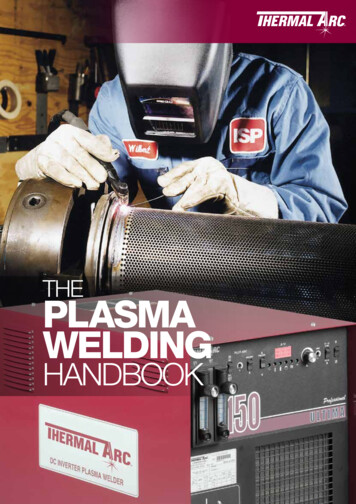
Underfill – surface activation at low temperatureSilicon Chip with Nitride PassivationCopperinterconnectConventional Treatment30umFB type polymer substrateFluxresiduesVoidsUnder Fill regionSolder flip chip bumpBenefits: Better epoxy wetting and reflow Fewer voids, increased yieldHigh density radical plasma treatmentO2/Ar at 50 CChemical, low UV and ions, low tempVoid-free underfil distributionExample: contact angle from 60-80 to 10 with O* radical exposure29
Wire Bonding Pad CleaningOrganic cleaning with O2 2nd step de-oxydation with H2After wire bondingdiesubstratediePAD (typically Ni,Au, Cu )substrateContamination and/or oxidation removal from the bond pads prior to wirebonding to increase reliability and yields30
Plasma DicingPLASMA DICING31
Current Wafer Dicing Technology- Sequential ProcessesBlade Dicing Damage: cracks/chips Orthogonal layouts required Slower for thin wafers ( 100μm) Slower for small die Poor accuracy Debris and water residuesLaser Dicing Damage: thermal, recast, debris,delamination, micro-cracks Orthogonal layouts required Slower for small die Multiple passes for thicker wafers32
Plasma Dicing: Parallel ProcessTape frameTapeChemical process – low temperatureNo silicon damageThinner wafers shorter processHigh selectivity low setup costNo additional mask requiredNo tape damageAccurate and precise ontrol of die szeDice any shapes/layouts33
Plasma Dicing BenefitsLower CostPer DieMore Die perWafer Thinner wafers faster dicing speed50µm thick wafer 3 min for dicing Ultra narrow streets ( 5µm) Less wafer starts, more capacity Freedom to dice any shape, multiNo Layout Designproduct wafersConstraints Rethink/relocate test/alignment areasHigherDie StrengthHighestAccuracy No chipping or micro-cracking No mechanical or thermal stress Die size variation determined by themask 34
Plasma Dicing on TapeLow temperature, highly selective DRIE conPolymer Smooth & CleanSidewallsTapeNo Tape DamageBOSCH ProcessUsing the device’s passivation,the plasma etches the siliconin the streets35
A Variety of Passivation Materials Can Serveas Masks 2014, Plasma-Therm,All Rights ReservedSiO2Photo Resist 2014, Plasma-Therm, AllRights ReservedSiO2 MaskDepth: 300µmWidth: 15µmSelectivity: 800No notchingPR MaskDepth: 150µmWidth: 15µmSelectivity: 430No notchingCuPolyimide 2014, Plasma-Therm,All Rights ReservedPI and exposed CuDepth: 250µmWidth: 100µmSelectivity: 250No notching36
Better dicing Better die qualitySuperior Die StrengthNo chipping, no lateral damageEnables thinner devices and wafers 2014, ON Semiconductor,All Rights Reserved 90µmEliminates “seal” rings 2014, ON Semiconductor,All Rights Reserved1 mm2 die37
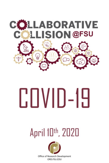
More Die Per WaferNormalized Die Countper Wafer and Die SizeDie Size (mm)
New Dicing Capabilities with SidewallProfile Control5μm 2015, Plasma-Therm, All Rights Reserved 2015, Plasma-Therm, All Rights Reserved 2015, Plasma-Therm, All Rights ReservedAdditional SidewallSurface AreaTapered ProfilesVariable SidewallQualityApplication-tailoredscallop size, withoutchippingImproved epoxyreflow & moldencapsulationDeliver smoothersidewalls in active areaand in non-active area.Plasma dicing provides smoother sidewalls, a ndnew sidewall profilecapabilities which can solve downstream packaging challenges39
New Dicing CapabilitiesDice any shape or layoutExamples: Power devices, multi-product wafers, RF devices, LEDs, image sensors, microphones 2014, Plasma-Therm LLC, All Rights Reserved40
Plasma Dicing AdoptionQualified (in production on MDS)Under QualificationPowerLEDRFIDIR Imagesensor3D MEMSIII-VCMOSWafer size6 & 8”4 & 6”8”8”8”3 & 4”8” & 12”Wafer typeSi,GaN/SiSi,GeSiSiSiGaAsSiStreet size10µm 5µm7µmRound die20µm30µm10µmWaferthickness 50µm 120µm100µm400µm100 300µm300µm50 to750µmAssemblyWirebondFlip ChipWirebondFlip ChipConfidentialFlip ChipWirebondFlip ChipCustomerconfidentialCustomerconfidential 2014, ON Semiconductor,All Rights Reserved 2015 Plasma ThermAll Rights Reserved 2015 Plasma ThermAll Rights Reserved 2015 Plasma ThermAll Rights Reserved41
AcknowledgementsChristopher Johnston, Plasma ThermThierry Lazerand, Plasma ThermDr. Marco Notarianni, Plasma ThermDr. Kenneth Mackenzie, Plasma ThermYannick Pilloux, Plasma ThermJulien Vitielo, Plasma ThermGordy Grivna, ON SemiconductorJason Doub, ON SemiconductorDr. Tomotak Tabushi, DISCODr. Frank Wei, DISCOHideyuki Sando, DISCOJS Jung, DISCOThank your for your contributions and materials toprepare this presentation42
Thank youContact: david.lishan@plasmatherm.com43
Solder flip chip bump Silicon Chip with Nitride Passivation Flux residues FB type polymer substrate Benefits: Better epoxy wetting and reflow Fewer voids, increased yield Chemical, low UV and ions, low temp Underfill -surface activation at low temperature Voids Void-free underfil distribution Conventional Treatment