Transcription
THEPLASMAWELDINGHANDBOOK
PlasmaThe FourthState ofMatterpage 2
ContentsPAGEIntroduction to Plasma Welding4-7ULTIMA 150 Plasma Welding System8-9Modular Plasma Welding Systems10-13System Layout10Power Supply and Welding Console11Coolant Recirculators12System Component Ordering Information12Plasma Welding Torches13Plasma Welding Torch Parts and Consumables14-17PWH/M 2A Parts and Consumables14PWH/M 3A Parts and Consumables15PWH/M 4A Parts and Consumables16PWM 300 Parts and Consumables17PWM 6A Parts and Consumables17Plasma Welding Controller18Cold Wire Capstan Feeder18-19Modes of Operation - Melt-in Fusion Welding20Modes of Operation - Keyhole Welding21Gas Selection22Troubleshooting23Service Test Procedures23page 3
PlasmaThe term Plasma, refers to a gas that hasbeen sufficiently ionized to conduct anelectrical current. As we see matter in theworld around us, we are usually consciousof its existence in three states . solid, liquidand gas. We are all aware of the differencebetween solids, liquids, and gases, and thefact that increasing the temperature changesa material from one state to another. Whenenough energy is applied to a gas, this willcause an ionization of the gases atomicstructure. This process is visible to us in theform of fluorescent lighting in our homes andoffices, lightning in the night sky, or even ourvery sun. Most of the visible universeis a type of plasma.When energy (heat) is added to a materialin a gaseous state, the temperature of thegas keeps increasing. If enough energy isadded, the temperature becomes high enoughthat the gas no longer exists as individualmolecules. The molecules come apart and thematerial made up of individual atoms, if thetemperature is further increased, the atomswill then lose electrons and become ions. Thismaterial then consists of a combination of ions(with a positive charge) and free electrons.Under these conditions, the matter now existsin a fourth state. the PLASMA state.Plasma has many properties that are similarto those of a gas but also some specialproperties that make it unique. The mostimportant property of the plasma, as faras welding is concerned, is that it containsfree electrons which allows it to easily carryan electrical current. The plasma weldingprocess does not have an exclusive on theuse of plasma as it also exists in all other arcwelding processes. Plasma welding utilizesthe developed hot gases to provide uniquebenefits to the welding operation.page 4
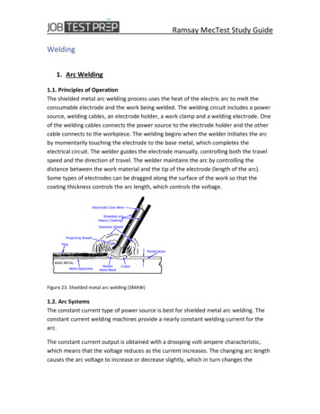
Plasma Arc Welding (PAW)PlasmaOUTPUTArc Welding(PAW) is a weldingprocess that heatsan inert gas to anextremely highPLASMA temperature so thatthe gas becomesionized and electrically conductive. Thisplasma gas is constricted into a columnby an orifice placed downstream of theelectrode which is protected inside thenozzle of torch. The plasma is used totransfer an electric arc to the workpieceto obtain the melting and coalescence ofmost metals and to constrict the arc duringthe welding process.PAWProcessAdvantagesOUTPUTMAX OUTPUTDC CC 150AMPSVOLTAGEAllmetalsINPUTamenableor TIGPOWER to GTAWHERTZwelding can be welded with the plasmaPHASEarc welding showsarc process. Plasmaits greatest advantages in the weldingof high volume repetitive productionoperations. These applications normallydemand repeatable welds on a nearcontinuous basis using the melt-in fusionmode and include spot fusion welds,corner edge welds, lamination welds andcircumferential / seam welds.208460VPlasma now has proven its value in thearea of highly repetitive automated welds.The process provides increased reliabilityand repeatability to meet today’s highstandards of productivity. It is frequentlyused as an alternate to the gas tungstenarc welding process (GTAW).5060For most applications, the plasma arcprocess offers increased electrode life,reliable arc starting, improved arc stability,better penetration control and reducedcurrent levels. In some cases plasmaoffers increased travel speeds, improvedweld quality, and less sensitivity tooperating variables.Plasma welding is not a new process tothe industry, but only in the past few yearshas it gained significant acceptance. Untilrecently, the process was consideredexotic and difficult to understand. Thiswas mainly due to the applications it wasbeing adapted to.Features & Benefits - The Protected ElectrodeOne of the most important features ofthe plasma arc welding process is theProtected Electrode which provideshigher efficiency and reduces downtime inmost applications.The tungsten electrode, which is securedinside the plasma torch and behindthe orifice, is protected from outsideimpurities that would normally attackits hot surface. With this protection, theelectrode is shielded from materials thatcan constantly attack an “exposed”electrode. The protected electrode in theplasma welding torch normally requires achange only once every 8 hours for mostoperations. This reduction in electrodechange allows for increased productivity.The electrode is secured externallyin the TIG welding process (GTAW).This exposes the electrode to thecontaminants (stamping and forming oils,degreasers, oxides, etc.) present on thesurface of the base material to be welded.These contaminants, under intensetemperatures, will attack and erode thetungsten electrode requiring the frequentchanging of the electrode on a repetitivebasis.It is not uncommon in many applicationsfor the electrode in the GTAW torch torequire replacement changes 1 to 2 timesper hour depending on part cleanlinessand production levels. The time requiredto change the electrode depends on theaccessibility of the torches on the fixtureapparatus. Five minutes or more may bespent on each electrode change in somecases, eating away costly productiontime.Multiplying the number of electrodechanges required in an 8 hour shift bythe time required for each change, anddividing by the total amount of productiontime available, will yield the percentageof lost production time. Based on thatnumber, it is now easy to figure parts lostdue to frequent electrode changes. Thisreduction in electrode change allows forincreased productivity.(See chart below)Typical Plasma/TIG Welding Productivity Benefit AnalysisCOMPARISIONTimeTIGHourDayPLASMA2081Minutes ToChangeElectrodes54,99224120Total Parts@ 100% CapacityTIG ElectrodeChanges17PlasmaElectrodeChanges04163Parts LostWith TIGParts LostNet GainWith Plasma Plasma Over 08,16078013,52094,640Value per PartProduction Parts/Financial Gain with Plasma194,640YearShift Hours per WeekDays Worked per WeekApplication: Outside corner welds home appliance245NOTE: 4 welds required on each part. For more information, contact Victor Technologiespage 5WA3YE
Plasma ArcWeldingAdvantages and DisadvantagesReliable, easy-to-operate Thermal Arc PlasmaWelding Systems boost profits and productivityby helping you achieve consistently high qualityrepeatable welds – manually or automatically.Whatever your application needs, the broad,versatile line of Thermal Arc consoles, torches,power supplies, and accessories provide theright tools for the job.Plasma arc welding is measurably the lower costprocess with savings gained through increasedproductivity, reduced scrap, reduced downtime andfewer electrode changes.Plasma arc welding offers many advantages over TIGWelding (GTAW - Gas Tungsten Arc Welding):ADVANTAGES: Reliable Arc Starting Protected Electrode Less Sensitive to Stand-Off Changes Improved Arc Stability at Low Current Lower Current Levels Required Reduced Heat Input or Distortion Arc is More Directional (Less Arc Wander) Improved Weld Geometry and Penetration Control Less Filler Material Required Reduced Current Levels Single-Pass Welds Minimized Weld Preparation Narrower Weld Beads Visual Proof of 100% Weld Penetration Improved Weld GeometryDISADVANTAGES: Limited to Flat, Horizontal, and Vertical-Up Positions More Sensitive to Variable Changes Limited to Automated Operationspage 6
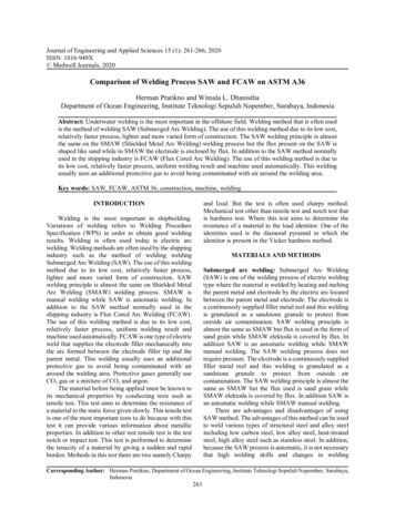
What Is Plasma Arc Welding?Simply stated, Plasma Arc Welding(PAW) is a superior variation to TIGwelding (GTAW) that encloses thetungsten electrode in a protectedenvironment (Figure 1) and deliversthe arc through a cooled copper tip.Enclosing the electrode protects itfrom contamination, thus substantiallyextending its life.The constant stable arc shape ofplasma results in consistent welds foreight hours or more of operation ascompared to automated TIG welding,where deterioration of the exposed TIGelectrode (Figure 2) can result in weldarc variations (Figure 3) in one hour orless of operation. Plasma arc weldinguses a pilot arc (Figure 4) to consistentlytransfer the arc to the work without therepeated use of high frequency current.PROTECTED ELECTRODEELECTRODESUsed TIG ElectrodeNew ElectrodeUsed Plasma ElectrodeFigure 1Figure 2TIG WELD SAMPLEPILOT ARCFigure 3Figure 4Pilot ArcAnother outstanding feature of thePlasma arc welding process is the PilotArc which provides reliable arc startingand contributes to the repeatabilityand increased productivity of plasmawelding.The Pilot Arc is a low current DC arcthat is sustained in the tip area of thetorch to ionize a gas as it passes aroundthe electrode and through the orifice.Arc initiation is provided by the pilotarc that transfers between the tungstenelectrode and the tip. It is started byimposing high frequency (from a smallhigh frequency generator or C.D. arcstarter inside the control console) ona low DC current for a short duration oftime to ionize the gas. Once the pilot archas been established, the requirementsfor high frequency are no longer needed.The pilot arc now remains on to reliablyassist the starting of the main transferredwelding arc from a separate DC powersource.Without the need for high frequencyused in TIG welding (GTAW), the erosionof the electrode by constantly etchingits surface is diminished. This eliminatesthe phenomena of inconsistent arcstarting, resulting in the loss of arcdirectability. The use of a pilot arcinstead of conventional high frequencycircuitry provides extremely reliable arcstarting. This repeatable arc initiationnearly eliminates significant downtimeand minimizes the number of rejectsor reworks due to poor welds thusreducing scrap.Constricted ArcAn orifice (also called a nozzle or a tip)which is inserted into the front end of thetorch body provides for the laminar flowof the plasma gas and constriction of thearc. The magnitude of this constriction isnormally controlled by three variables . theorifice diameter, the plasma gas flow rate,and the electrode setback (the distancethe electrode is recessed within the tip).The arc will be most constricted when thetorch is operated at higher plasma gas flowrates and the electrode placed at maximumsetback. This type arc is typically usedwhen trying to achieve keyhole single passwelds requiring maximum penetration,narrower weld beads, minimized heataffected zone, and reduced base materialdistortion. Keyhole welding is generallyused on material thickness ranging from.090” (2.3 mm) to .250” (6.4 mm).By reducing the electrode setback andplasma gas flow rates, a softer, lessconstricted arc will occur. This type arc istypically used for the melt-in fusion (nonkeyhole) mode and allows for faster travelspeeds on reduced base material thickness.010” (.3 mm) to .187” (4.7 mm).page 7
ULTIMA 150Plasma WeldingSystems SYSTEM INCLUDES: POWER SOURCE,TORCH, COOLANT & SPARE PARTS KITFOR PLASMA WELDINGBELOW 150 AMPSULTIMA 150 PLASMA WELDING SYSTEMS200-460VAC, 1/3PH, EMCDC AMPSYSTEM DESCRIPTIONRATING0.5-75 AMPS10-100 AMPS50-150 AMPSULTIMA 150OPTIONSW/25 FTTORCH & LEADSPWH-2A, 70 DEG1-1555-211-1556-21PWH-2A, 90 DEG1-1555-221-1556-22PWH-2A, 180 DEG, OFFSET1-1555-231-1556-23PWH-3A, 70 DEG1-1555-311-1556-31PWH-3A, 90 DEG1-1555-321-1556-32PWH-3A, 180 DEG, OFFSET1-1555-331-1556-33PWH-4A, 70 DEG1-1555-411-1556-41PWH-4A, 90 DEG1-1555-421-1556-42PWH-4A, 180 DEG, OFFSET1-1555-431-1556-43PWH-4A1, 180 DEG, INLINE1-1555-531-1556-53ULTIMA 150 POWER SOURCE ONLY3-2772QUICK DISCONNECT KIT(ALLOWS EXISTING TORCHES TOBE CONVERTED FOR USE WITHULTIMA 150)5-2990REPLACEMENT TORCHESPARTNO.W/12.5 FTTORCH & LEADSDESCRIPTIONREPLACEMENT TORCHESPARTNO.DESCRIPTIONREPLACEMENT TORCHESPARTNO.DESCRIPTIONPWH/M-2A TORCH (QUICK DISCONNECT)PWH/M-3A TORCH (QUICK DISCONNECT)2-210070 deg. (H), 3.8m2-211070 deg. (H), 3.8m2-212070 deg. (H), 3.8m2-210470 deg. (H), 7.6m2-211470 deg. (H), 7.6m2-212570 deg. (H), 7.6m2-210190 deg. (H), 3.8m2-211190 deg. (H), 3.8m90 deg. (H), 7.6m90 deg. (H), 7.6m90 deg. (H), 3.8m2-21052-21152-21192-2102180 deg. (H), offset 3.8m2-2112180 deg. (H), offset 3.8m2-2106108 deg. (H) offset 7.6m2-2116108 deg. (H) offset 7.6m2-2103180 deg. (M), offset 3.8m2-2113180 deg. (M), offset 3.8m2-2107180 deg. (M), offset 7.6m2-2117180 deg. (M), offset 7.6mpage 8PWH/M-4A1 TORCH (QUICK DISCONNECT)2-212690 deg. (H), 7.6m2-2121180 deg. (H), offset 3.8m2-2127108 deg. (H) offset 7.6m2-2122180 deg. (M), offset 3.8m2-2128180 deg. (M), offset 7.6m2-2123180 deg. (H), inline 3.8m2-2129180 deg. (H), inline 7.6m2-2124180 deg. (M), inline 3.8m2-2130180 deg. (M), inline 7.6m
ULTIMA 150 - Features and Benefits 0.5-150 Amp current range - providing qualityperformance on a wide variety of applications Smooth DC arc - repetitive, high quality welds Pilot arc - repeatable arc starting reducing defects andrework Smart Logic - circuit protects unit from damage ifimproper voltage is applied Current Limiter - limits power source output to torchcapability to avoid torch damage Preview Set Current - eliminates costly test set-ups/displays actual current/voltage Protection devices:- Coolant flow protection/interlock- Coolant temperature protection/interlock- Console temperature overload detection/interlock Simple interface - automated or manual control3456789 10 11211 - System On/Off2 - Shield Flow Control3 - Plasma Flow Control4 - Pilot Arc On/Set5 - Pilot Current Adjust6 - Pilot Current Preview7 - Weld Current Preview / Actual8 - Weld Current Adjust9 - Current Limiter Adjust10 - Weld Current Range11 - Remote / Panel ControlMACHINE SPECIFICATIONSProcessesPAW Plasma Arc Welding100A / 18V @ 100%Rated Output150A / 25V @ 50%Open Circuit VoltageRated Output:Amperage RangeWarrantyDimensions (H x W x D)WeightShipping Weight60V DC150A @ 50%Low: 0.5 - 15 AHigh: 5 - 150 A2 Years457mm x 381mm x 724mm59 kg72 kgPRIMARY POWERPrimary VoltageSupply FrequencyNumber of Phases400 VAC50/60 Hz3 phThe Ultima 150 Plasma Arc Welding System is self contained in asmall package with a 150 amp power supply, coolant recirculatorand control console with many advantages over traditionalautomated TIG welding. Its pilot arc circuit results in consistentarc starting every time, reducing scrap and improving processcontrol for repeatable, high quality welds. The Ultima 150 virtuallyeliminates problems of high frequency interference (noise) withCNC controllers, phone systems and computers which arecommon with the TIG welding process. The perfect machine forMelt-In Fusion welding with power output needs under 150 ampswhen working on materials 3/16" (4.7 mm) thick or less.The Ultima 150 has a number of features for ionized coolantprotection, coolant flow and console temperature monitors, aswell as gas flow meters. Equipped with system status and errorindicator lights to monitor input voltage, output current and pilotarc activity.It can utilize any number of current Thermal Arc quick disconnecthand-held or automated torches and delivers high heatconcentration and arc directability to work segment allowingfor greater penetration and reduction in current levels in manyapplications.OPTIONAL REMOTE CONTROLSPRODUCTPART NO.Foot Control, 25 ft. (Includes 7-3316 Adapter Cable)7-3080HP-100 Hand Held Remote Control, 25 ft. (Req. 7-3316 Adapter Cable)10-2005Adapter Cable7-3316page 9
Moldular Plasma Welding SystemsREQUIRED FORPLASMA WELDINGABOVE 150 AMPSFiller Metal/Wire Drive(not shown)Plasma Modular EquipmentPlasma Welding TorchThermal arc offers everything to build thecomplete plasma arc welding system for yourkeyhole needs over 100 amps for welding metalsgreater than 3/16” thick.A typical plasma welding system consists of:n Welding Consolen DC Power Supply with a Suitable WeldingRangen Plasma Welding Torch (Manual or Mechanised)n Closed Loop Coolant Recirculatorn Inert Gas Flowgauge Regulators(Manual or Mechanised)A plasma welding torch suitable for the particularwelding operation should be used. Torches areavailable with various head and size configurations.All are liquid cooled. The orifices of some torchesare also liquid cooled to provide improved orificelife and higher current carrying capacity. Plasmatorches use tungsten electrodes, which are normally2% thoriated.Welding ConsoleClosed Loop Coolant RecirculatorThe pilot arc control console is the ‘mixing box’ intowhich the power, gases and coolant are controlledand monitored. It has a small DC power supply forthe pilot arc. Some consoles provide additionalcontrols and digital meters to assist in weldparameter control.A coolant recirculator of a nonferrous design mustbe used. The use of deionized water to preventelectrolysis in the torch is required.DC Power SupplyOptional AccessoriesA typical DC power supply with constant-currentcharacteristics, remote contactor/current control,and suitable welding range is recommended formost operations. A solid-state power supply with anon-mechanical contactor is recommended whenperforming high duty cycle short duration welds.Plasma arc welding is done almost exclusively withthe use of straight polarity (DCEN). The use of anAC Square-Wave power supply is recommended forthe welding of aluminum or aluminum alloys.Options for the plasma welding system couldinclude Weld Controllers with remote handpendants and cables. A Weld Sequencer packagewould be needed to monitor and control pulse, weldtiming, current and gas slopes. For applicationsusing filler metals, a Wire Feeder Capstan withspool assembly and torch bracket would berequired.page 10
WC 100B Welding ConsoleAutomatic/Manual Operation, Pilot ArcCompatible with all Thermal Arc plasma welding torches,the WC 100B features reliable arc starting by means ofa pilot arc. It offers advantages in low-current weldingoperations and in repetitive, high-duty-cycle, automaticapplications. The pilot arc can be used in eitherinterrupted or continuous mode. The latter providesgreater arc stability along with instant arc starting atlow currents or in high-duty-cycle, fast cycling welding.Other feature include: LED amperage/voltage display;large, easy-to-read plasma and shield gas flowmeters;internal torch leads connections for increased safety; Hi/Low pilot current switch to provide the best arc startingcharacteristics at various main arc current levels; plugin enclosed relays; and auxiliary control receptacle forautomatic or manual operation.PowerMaster PLUS 400SP400 Amp Welding Power SourceMACHINE SPECIFICATIONSNominal Supply Voltage400V 15%Nominal Supply Frequency50/60HzPhaseStandard3 phaseIEC 60974-1Power Factor at Maximum Output0.99Recommended Fuse SizeInput Current at Maximum Output32 Amp28.1 AmpTorch CoolingWelding Current RangeWelding Voltage RangeNominal DC Open Circuit Voltage100% Rated Duty Cycle60% Rated Duty CycleDimensions (HxWxD)WeightWarranty PeriodFan Cooled /Liquid Cooled5-400 Amp15.2-34V81V350 Amp @ 31.5V400 Amp @ 34V855 x 445 x 1116 mm112kg3 YearsThe PowerMaster 400SOP Welding Power Source is designed to deliver the welding current power you need for those higheramperage plasma welding applications. The unit is perfectly fitted to connect to the Thermal Arc WC-100B Plasma WeldingConsole when used with the accessory remote control, cables and interface kit listed on page 12.This workhorse will meet the productivity requirements you need on automated plasma welding applications.page 11
Coolant RecirculatorsFor Modular Plasma Welding SystemsHE-100A Coolant RecirculatorHigh efficiency and completely non-ferrous internalconstruction (including a reusable metal filter) makethe HE 100A a useful, dependable companion for anyThermal Arc plasma welding system to 300 Amps.A positive displacement, rotary vane pump deliversa maximum of 2.3 gpm (8.7 lpm) at 100 psi (.9 lpmat 7 kg/cm2). The pressure is adjustable. Maximumrating is 20,000 BTU/hr (5040 K/Cal/hr) (based on100 F [38.8 C] difference between ambient air andhigh coolant temperature, and 40 F [4 C] differencebetween high and low coolant temperature).HE-150 Coolant RecirculatorThe HE-150 is required for applications above 300Amps, and is used with the PWM-6A Torch. Theunit delivers a maximum of 4 gpm at 125 psi, and amaximum rating of 65,000 BTU/hr (based on 100 F[38.8 C] difference between ambient air and highcoolant temperature, and 40 F [4 C] differencebetween high and low coolant temperature).Moldular Systems Ordering InformationWELDING POWER SUPPLYPRODUCTPowerMaster PLUS 400SPAMP RATING / DUTY CYCLEINPUT VOLTAGEPART NO.350A @ 100% 400A @ 60%400V, 3Ph, 50/60HzW1000303PPACCESSORIESHR911 Remote ControlCAN Cable14-Pin Interface KitREQUIRED to use PowerMaster PLUS 400SPas part of a modular plasma welding installationW4000100W7000450W4012101WELDING CONSOLEPRODUCTWC-100B ConsoleAPPLICATIONINPUT VOLTAGEPART NO.KEYHOLE(USES FLOWMETER 0.2 - 3.6 SCFH)400V, 3Ph, 50Hz3-2657-14KEYHOLE(USES FLOWMETER 0.8 - 7.0 SCFH)400V, 3Ph, 50Hz3-2657-24COOLANT RECIRCULATORSPRODUCTNOTEMAX RATINGINPUT VOLTAGEPART NO.HE-100A CoolantRecirculatorFor Systems Less Than 300A20,000BTU/HR230V, 1Ph, 50Hz7-3011-3HE-150 CoolantRecirculatorREQUIRED for PWM-6A torch(Rating 300A DC and above)65,000BTU/HR230V, 1Ph, 50Hz7-2972-3page 12
Plasma TorchesManual Plasma Torches70 , 90 and 180 (PWH)WELDING PROCESSES:PLASMA (PAW)Plasma Torches come complete with: Torch Spare Parts Kit Rack & Pinion AssemblyRack & Pinion AutomatedPlasma Torches 180 Inline or Offset (PWM)Torch2ATypePartNo.PWH-2A70 2-244312.5 ft (3.8 m)PWH-2A90 2-250625 ft (7.6 m)PWM-2A180 Offset withrack & pinion2-248012.5 ft (3.8 m)2-252712.5 ft (3.8 m)2-259925 ft (7.6 m)PWH-3A70 4ATorch DimensionsAB7-15/16" 1-11/16"(202 mm) (43 mm)75Amps(DCSP)2,000 BTU/hr(504 K/Cal/hr)7-3/4"1/4 gpm coolant (196 mm)flow @ 50 PSI(0.9 lpm @3.7 kg/cm2)18-1/4"(463 mm)1-11/16"(43 mm)CD5/8"(16 mm)7/8"(22 mm)5/8"(16 mm)7/8"(22 mm)8-3/4"2-5/8"(222 mm) (67 mm)7/8”(22 mm)1-1/16"(27 mm)12.5 ft (3.8 m)25 ft (7.6 m)2-261612.5 ft (3.8 m)2-262125 ft (7.6 m)PWM-3A180 Offset withrack & pinion2-253112.5 ft (3.8 m)2-262425 ft (7.6 m)PWH-4A70 2-282112.5 ft (3.8 m)2-282025 ft (7.6 m)12-1/2" 3-3/16"(318 mm) (81 mm)1-1/4”(32 mm)1-3/8"(35 mm)PWH-4A90 2-281912.5 ft (3.8 m)12-1/4" 3-3/16"(311 mm) (81 mm)1-1/4”(32 mm)1-3/8"(35 mm)PWM-4A180 Offset withrack & pinion2-248212.5 ft (3.8 m)2-259225 ft (7.6 m)PWH-3A180 OffsetPWM-4A1180 Inline withrack & pinion300 PWM-3002-285012.5 ft (3.8 m)2-285125 ft (7.6 m)2-280425 ft (7.6 m)2-284512.5 ft (3.8 m)2-284625 ft (7.6 m)2-273112.5 ft (3.8 m)2-272025 ft (7.6 -3/8"9-1/4"15"(21 mm) (235mm) (381 mm) (35 mm)2-2529PWH-4A1180 Inline6ACoolantRequirements2-2623PWH-3A90 3ATorch Lead CurrentLengthRating(PWM designated models only) 12.5 ft (3.8 m) or 25 ft (7.6 m) Lead Operator’s Manual (not shown)8-1/2"2-5/8"7/8”1-1/16"(216 mm) (67 mm)(22 mm)(27 mm)6,000 BTU/hr(1513 K/Cal/hr)1/3 gpm coolantflow @ 50 PSI(1.25 lpm @3.7 kg/cm2)Min.Max.19-1/4"1"1-3/8"9-1/4" 16-3/4" (35(489 mm) (25 mm) (235mm)mm) (425 mm)8,000 BTU/hrMin.Max.(2017 K/Cal/hr)18"1-3/4"1-3/8" 1-1/4"16"(321/2 gpm coolant (457 mm) (44 mm) 8-1/4"(35mm) mm)(209 mm) (406 mm)flow @ 50 PSI(1.9 lpm @3.7 kg/cm2)Min.Max.21"1-3/4" 11-1/4"1-3/8" 1-1/4"19"(32(533 mm) (44 mm) (286(35mm) mm)mm) (483 mm)300Amps(DCSP)12,000 BTU/hr(3025 K/Cal/hr)Min.Max.3/4 gpm coolant 22-3/16" 2-1/"21-3/8" 1-5/8"8-1/4"8-1/4" (35(41flow @ 100 PSI(.56 m) (64 mm) (209mm) mm)mm) (209 mm)(1.9 lpm @ 3.7 kg/cm2)500Amps(DCSP)20,000 BTU/hr(5042 K/Cal/hr)Min.Max.13-1/2" 1-1/8"2-1/4"2 gpm coolant8-1/4"8-1/4"flow @ 50 PSI (1.9 (343 mm) (29 mm) (209 mm) (209 mm) (57 mm)lpm @ 3.7 kg/cm2)page 13
Torch Parts & ConsumablesPWH/M 2A Torch75 Amp Plasma Welding TorchDESCRIPTIONSpare Parts KitTorch Head - 70 Torch Head - 90 Torch Head - 180 (offset)Torch Leads set, 3.8mTorch Leads set, 7.6mPWH torch handleQuick Disconnect Adapter KitShield Cup - Standard TipShield Cup - Extended TipTip - 35A, (.045), StandardTip - 55A, (.062), StandardTip - 75A, (.081), StandardTip - 15A, (.031), ExtendedTip - 25A, (.045), ExtendedTip - 35A, (.062), ExtendedTip - 50A, (.081), Extendedpage 14REF. PART 08028-208228-2083DESCRIPTIONREF. PART NO.Electrode (.093), Standard88-2033Electrode (.093), Extended88-2006Electrode (.040), Standard88-2044Electrode (.040), Extended88-2046Gas Distributor (.093)38-2040Gas Distributor (.040)38-2042Shield Cup Gasket48-2036O-Ring, Back Cap68-2035Collet for .093 Electrode78-2039Collet for .040 Electrode78-2041Back Cap - Standard98-2032Back Cap - Extended98-2030Electrode Gauge / Wrench8-2021
Torch Parts & ConsumablesPWH/M 3A Torch150 Amp Plasma Welding TorchDESCRIPTIONREF. PART NO.Spare Parts KitDESCRIPTIONREF. PART NO.5-2985Tip - 30A, (.031), Extended29-1788Torch Head - 70 68-3030Tip - 50A, (.046), Extended29-1789Torch Head - 90 68-3031Tip - 75A, (.062), Extended29-1790Torch Head - 180 (offset)68-3032Tip - 100A, (.081), Extended29-1791Torch Leads set, 3.8m4-2615Tip - 130A, (.093), Extended29-1811Torch Leads set, 7.6m4-2624Electrode (.093), Standard98-2007PWH torch handle9-1757Electrode (.093), Extended99-1775Quick Disconnect Adapter Kit5-2990Gas Distributor39-2240Shield Cup18-3038Shield Cup Gasket48-3057Shield Cup with gas lens18-3040Gas Diffuser58-3059Tip - 10A, (.014), Standard28-3052O-Ring, Back Cap78-0527Tip - 15A, (.022), Standard28-3053Collet89-1780Tip - 30A, (.031), Standard29-1782Back Cap - Standard109-1779Tip - 50A, (.046), Standard29-1783Back Cap - Extended109-1803Tip - 75A, (.062), Standard29-1784Electrode Gauge / WrenchTip - 100A, (.081), Standard29-1785Tip - 130A, (.093), Standard29-17959-1810page 15
Torch Parts & ConsumablesPWH/M 4A Torch220 Amp Plasma Welding TorchDESCRIPTIONREF. PART NO.Spare Parts Kit5-2986DESCRIPTIONElectrode (.187), StandardREF. PART NO.39-1827Torch Head - 70 98-4014Electrode (.187), Extended39-1834Torch Head - 90 98-4015Gas Distributor49-2204Torch Head - 180 (offset)98-4016LinerTorch Head - 180 (inline)98-4054Shield Cup Gasket68-4069Torch Leads set, 3.8m4-2525O-Ring, LinerTorch Leads set, 7.6m4-2544O-Ring, TorchPWH torch handle9-5914Gas Diffuser (Threaded)78-4040Quick Disconnect Adapter Kit5-2990Gas Diffuser (Slip-on)78-40878-40118-05608-0528Shield Cup - Ext, Tip, (Threaded)18-4064Collar88-4024Shield Cup - Std, Tip, (Slip-on)18-4088O-Ring, Back Cap108-0530Tip - 100A, (.062), Standard29-1847Collet119-1876Tip - 125A, (.093), Standard29-1848Back Cap - Standard128-4158Tip - 150A, (.125), Standard29-1849Back Cap - Extended129-1877Tip - 100A, (.062), Extended29-1890Electrode Gauge / WrenchTip - 125A, (.093), Extended29-1891Tip - 150A, (.125), Extended29-1892page 169-1873
Torch Parts & ConsumablesPWM 300 Torch300 Amp Plasma Welding TorchDESCRIPTIONREF. PART NO.Spare Parts KitTorch Head - 180 11Torch Leads set, 3.8mTorch Leads set, 7.6mDESCRIPTIONREF. PART NO.5-2910Gas Distributor78-66518-6649Liner68-65094-2525Shield Cup Gasket98-65124-2544O-Ring, Liner59-2956Shield Cup - Brass18-4373O-Ring, Torch108-0531Shield Cup - Ceramic18-6542Gas Diffuser88-6652Tip - 200A, (.093)28-4370Shield Adaptor for 8-6542Tip - 250A, (.113)28-4371O-Ring, Back Cap128-3487Tip - 300A, (.125)28-4372Collet138-6650Electrode (.178)49-1827Back Cap148-66548-6541Electrode Gauge / Wrench8-6653PWM 6A Torch500 Amp Plasma Welding TorchDESCRIPTIONREF. PART NO.DESCRIPTIONREF. PART NO.Torch Head - 180 98-6502Gas Distributor38-6547Shield Cup18-6542Liner68-6509Tip - 100A (.067)28-6526Sleeve78-6565Tip - 200A (.099)28-6527Shield Cup Gasket88-6512Tip - 300A, (.125)28-6528Shield Adaptor58-6541Tip - 400A, (.156)28-6539O-Ring, Back Cap108-3487Tip - 500A, (.187)28-6540Collet118-6548Electrode 100A - 300A48-6545Spring128-5031Electrode 400A - 500A48-6549Back Cap138-6520Tip Wrench8-6517page 17
Plasma Welding ControllersWELD TIMERS, WELD PULSERS, CURRENT SLOPING, GAS SLOPINGPRODUCTCONNECTIONINPUT VOLTAGEWC-1 Weld Process Controller110/230V, 1PH, 50/60HZPART NO.600279Contol Cable, 10 ft.WC-100B to WC-19-4129Remote Hand Pendant, 25 ft.WC-1600280WC-1 Weld Process ControllerWF-100 Wire Capstan FeederSYSTEM FEATURES:n Remote Hand Pendantn Adapter Cables Includedn Full-Featured Current Pulser controlswarpage, penetration and weld puddlen 32 User-Selectable Weld SchedulesSYSTEM FEATURES:n Plastic Deforms the Filler Wire virtuallyeliminating wire castn Increased Drive Force eliminates wire slip,flattening and damage to wire surfaceThe Thermal Arc WC-1 Weld Process Controlleradds a compact packaged micro-processorsystem to the plasma welding package providingaccurate and repeatable parameter control overthe entire welding system. The Sloper Function isdesigned to permit the development of a completesequence of operation for a specific weldingjob. With two Programmable Outputs, the first isused to control the Plasma power source and thesecond controls a Cold Wire Feed Motor DriveControl. The perfect fit to control your ModularPlasma System.The Thermal Arc WF-100 Cold Wire CapstanFeeder is a compact, precision wire feeder forrobotic or automation fixture applications. TheCapstan’s small size and light weight (less than6 lbs.) allows it to be placed directly on theautomated fixture or robot wrist and also providesan increase in wire drive contact area by wrappingthe wire around the wire drive wheel. The IntegralWire Straightener on the discharge side of thefeeder allows the wire drive to precisely locate thefiller wire independent o
as welding is concerned, is that it contains free electrons which allows it to easily carry an electrical current. The plasma welding process does not have an exclusive on the use of plasma as it also exists in all other arc welding processes. Plasma welding utilizes the developed hot gases to provide uniq