Transcription
Basic Troubleshooting GuideRevised June 2009
ContentsBevel Basics .3How Torch Position Affects Bevel .4What Causes Bad Cuts .5Gear Ratio Calibration .7Tightening Set Screws .8Adjusting Belt Tightness .9Height Control Troubleshooting .10Basic System Test Points .11AVHC Basic Overview .12M100/101 Time Out Error .131-866-571-1066 x3International: 775-673-2200 x3Email: support@torchmate.comToll Free:
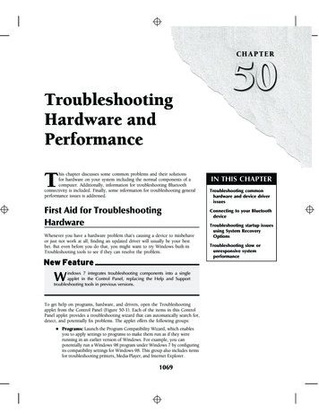
Bevel BasicsCorners can also have a bit more bevelthan a normal cut. This is causedwhen the machine slows down tomake the direction change. This canbe minimized by adjusting rampingrates and start stop values. It is alsopossible in some cases to use a loweramperage to allow for slower travelspeeds. This reduces the amount ofslowdown through corners.Bevel is caused by the motion ofthe plasma gas as it is emitted fromthe nozzle. In plasma cutting it isunavoidable. High definition plasmaproduces less bevel than a standardcutter.Torch height, air pressure, quality ofair, direction of cut, and consumablecondition all contribute to how muchbevel a cut has.Sharp corners can be achieved bycutting a larger shape that puts theslow down and acceleration of themachine into a scrap area. Thiscut is used more on thick materialswhere the corner bevel is increaseddramatically.In the process to create a plasma arcfor cutting the gas must be shaped intoa vortex. Because of this an arc willhave a direction of rotation. This willcause one side of the cut to have morebevel than the other. To ensure thatthe best bevel is on the part, properdirection of travel is necessary.The direction of cuts are referred toas “conventional” and “climbing”. Ina conventional cut the torch will gocounter-clockwise on outside cuts andclockwise on inside cuts. A climbingcut is the opposite. For plasma thebest bevel is achieved by using aclimbing cut. Basically the best cutbeing to the right of the direction oftravel.3Consumables if not replaced regularlycan cause bevel. If a tip wears outor slag builds on it the air flow isredirected in ways that can causerandom bevel and inconsistent cutquality. Always check consumableswhen troubleshooting bevel.ConventionalClimbingThe easiest way to reduce bevel is bycutting at the proper speed and heightfor the material and amperage thatis being cut. Constant air pressureand volume that is clean and dryalso decreases the bevel. Usingconsumable in good condition alsoprevents excessive bevel.
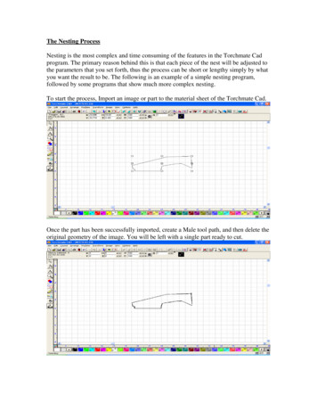
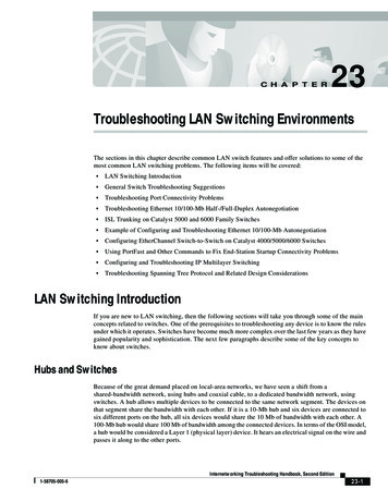
How Torch Position Affects BevelCorrect torch heightTorch square to materialTorch angled to materialIncorrect torch heightTorch too highIncorrect torch heightTorch too lowPosition oftorch whilecuttingBevel offinished partEqual bevel on all sidesUnequal bevelExcessive bevelReversed bevelMinimal bevelOne side may be straight theanother excessively beveledCut may not go all theway through materialTorch may contact materialand short out or damage tipLongest consumable lifeCan be caused by worn tip4
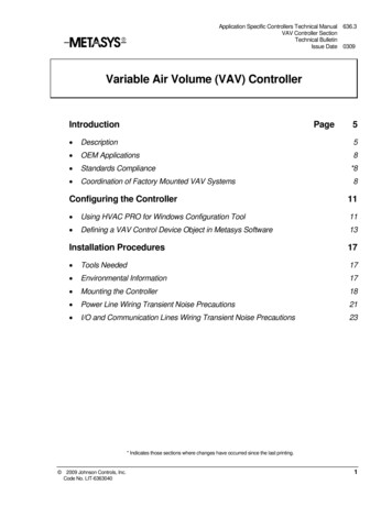
What Causes Bad CutsInstances where the metal was not fully cutindicate a few different problems. If the groundclamp was not properly attached to the materialthis can happen. A similar cut can happen ifthere was a drop in air pressure, moisture in theair line, or a drop in power. A third cause is ifthe torch contacts the material, most plasmacutters will go into a low power mode when thishappens causing the cut not to penetrate all theway.When a machine’s performance suddenlychanges or degrades gradually from one partto another this generally indicates somethingmechanical has changed. In cases like thischeck tightness of belts and set screws. Ensurethat the gear to gear rack spacing is adjustedproperly. The square of the gantry to the tablecan also cause parts to be out of shape.A cut where the path does not return to the startpoint indicates mechanical slipping or binding.In some cases it will be clear which axis islosing position. Examine the particular axisfor loose set screws, loose belts, or physicalobstructions.5
In some cases the slipping in one direction willbe offset by slipping in the opposite directionof travel. This allows the part to be cut out butthe tool path was not followed correctly. Setscrews, belts, gear spacing, and square of thetable should be checked.When the machine begins to move before apierce is completed the cut will not complete.In this case the dwell time or pierce delay mustbe adjusted to allow for enough time to piercethe material.6
Gear Ratio CalibrationIf one or both axes of travel move an incorrectdistance but that distance is consistent thisindicates an incorrect gear ratio. A gear ratiotest is required to calibrate the table. Basicallythe machine will be told to move a certaindistance and the actual distance moved will bemeasured.To move the table a certain distance go to thepoint menu and type in the desired distanceto move. Measure how far the table actuallymoves. Using those two numbers and thecurrent gear ratio a corrected gear ratio can befound. To find the current gear ratio and tochange it go to“Configuration” “Machine” “Mechanics”To Calculate the Gear RatioTake the distance told to travel and divide by the actual distance traveled.DISTANCE TOLD TO TRAVEL / ACTUAL DISTANCE TRAVELEDTake this number and multiply by the current gear ratio.(DISTANCE TOLD TO TRAVEL / ACTUAL DISTANCE TRAVELED) X CURRENT GEAR RATIOThis number is the corrected gear ratio.7
Tightening Set ScrewsA loose set screw is the most common cause forpoor cut shape. Ensure that these are checkedfor tightness regularly.8Set Screws
Adjusting Belt TensionBelts should be adjusted hand tight. Ensure thatthere is no slop or backlash between the twopulleys.9
Height Control TroubleshootingAn automatic voltage height control relies ona connection to the plasma cutter to receive araw arc voltage signal. This is used to maintainthe height of the torch from the work piece.While cutting if the height climbs away from thematerial the “set voltage” is too high. Likewiseif the torch tends to dive into the material the“set voltage” is too low.Most issues with the height control happenwhen it comes down to sense where the materialis. During this operation the motor is lookingfor a small amount of resistance. If the heightcontrol does not come down all the way to thematerial before trying to fire this indicates thatenough resistance was sensed during travel.The cause of this resistance can range from asmall piece of slag getting caught in the acmescrew to a severe lack of preventative cleaningthat necessitates a full break down and cleanup. The first step to try would be to wipe downthe screw and rods to ensure that no smallobstructions are present. If this step does notremedy the problem a full cleaning is necessary.10When reassembling or adjusting the lifter stationit is also critical to ensure that the two guiderails are parallel. If they are not this can alsocause binding and behavior similar to a dirtylifter station.
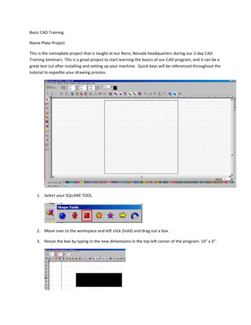
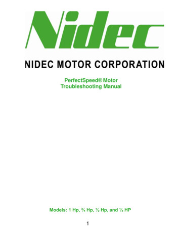
Basic System Test PointsSignal GeneratorOut6Out5Out4Out3Out2Out1All output lines are 0V offand 5V active when readacross the ground.In7In6In5In4OUTPUTINPUTMachineInterfacefor PlasmaIf an AVHC is used this connectionwill go to “Start”. If no AVHC isused the connection will go to theplasma cutter start wires.Limit Switch CableIn 1In 2In 3In 4In 5After the AVHC has cycled downto the material this connection willread continuity if the cut is on. Whenoutput line is deactivated this willread open.TORCHAutomatic VoltageHeight Control(AVHC)START11In2In1All input lines can be set to normallyopen or normally closed in the softwareOutOutGND21When output 1 is active the twoinside screws will have continuity.All other times it will read open.In3GND GND GND GND GND GND GND GNDInterface CableOPT OutGND 8OPT Out 5V 7In8
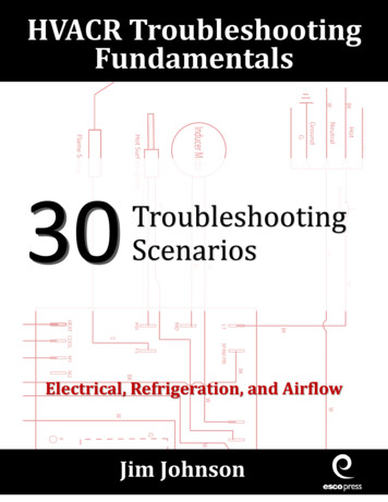
AVHC Basic OverviewVOLTS- The volts connection is an input from the raw arcvoltage points on a plasma cutter. This connection is polarityspecific and accepts a DC voltage signal. With the connectionsremoved the points should read a dead short when the AVHC isoff and 1 MΩ when the unit is on.TORCH- The torch connection is an output used to activate theplasma cutter. This connection is a normally open dry contactthat will close to turn the torch on.PIERCE- The pierce connection is an output used to relay theOK to move signal to the signal generator. This connectionis a normally open dry contact that will close when a signalis received from the OK to move connection, or the piercedelay has expired depending on the configuration of the systemcomponents.CORNER- Corner is not used in Torchmate systems.OK TO MOVE- The OK to move connection is an inputthat receives a normally open signal from the plasma cutterwhen it switches from a pilot arc. This signal is also called atransfer signal. Some plasma cutters do not send this signal, theconnection is not necessary to run.START- The start connection is an input that accepts a normallyopen signal from the machine interface for plasma to activate theAVHC’s function.12STARTOK TO MOVECORNERFAULTPIERCETORCHVOLTSFAULT- The fault connection is an output connected to the signalgenerator. This connection is a normally open dry contact thatwill close if the program needs to be paused by the height controlunit. The pause will generally occur if voltage is not detected inautomatic mode or an OK to move signal was expected but notreceived.Automatic Voltage Height Control(AVHC)
M100/101 Time Out ErrorM100/101 TIME OUT ERRORS- When operating the table an M100/101time out error can happen if the signal generator never receives a signal fromthe pierce connection.If a plasma cutter has an OK to move connection the signal originates whenthe plasma cutter transferrers from a pilot arc. This is received by the AVHCat the “OK TO MOVE” connection, from there it is sent along to the signalgenerator through the “PIERCE” connection. The pilot arc transition will nothappen if the plasma is trying to start over air or an area that is already cutor if the ground clamp is not connected. The pierce signal will not be sent if“Piece Complete” is disabled in the AVHC setup menu.If a plasma cutter does not have an OK to move connection to signal is sentfrom the AVHC through the ‘PIERCE” connection to the signal generatorafter the pierce delay time. If “OK to move” is enabled in the AVHC setupmenu and no signal is received the signal will never be sent. Ensure that“OK to move” is disabled.In both cases a loose connection on any of the wires will cause the error.13
the plasma gas as it is emitted from the nozzle. In plasma cutting it is unavoidable. High defi nition plasma produces less bevel than a standard cutter. Torch height, air pressure, quality of air, direction of cut, and consumable condition all contribute to how much bevel a cut has. In the process to create a plasma arc