Transcription
American J. of Engineering and Applied Sciences 3 (1): 83-89, 2010ISSN 1941-7020 2010 Science PublicationsComparative Study of Different Underfill Material on Flip Chip CeramicBall Grid Array Based on Accelerated Thermal Cycling1, 3Z. Kornain, 1A. Jalar, 2N. Amin, 3R. Rasid and 4C.S. FoongInstitute of Microengineering and Nanoelectronics, University Kebangsaan Malaysia,43600 UKM Bangi, Selangor Darul Ehsan, Malaysia2Department of Electrical, Electronics and System, University Kebangsaan Malaysia,43600 UKM Bangi, Selangor Darul Ehsan, Malaysia3School of Applied Physics, University Kebangsaan Malaysia,43600 UKM Bangi, Selangor Darul Ehsan, Malaysia4Freescale Semiconductor, Free Industrial Zone Sungai Way,47300 Petaling Jaya Selangor, Malaysia1Abstract: Problem statement: This study mainly to study the effect of several commercial underfillmaterials to the reliability of HiCTE Flip Chip Ceramic Ball Grid Array (FC-CBGA) package due toAccelerated Thermal Cycling (ATC) effect. Approach: The warpage condition of package, die backstress, interfacial die shear stress, and solder bump fatigue for different commercial underfills wereassessed and compared via a commercial Finite Element Analysis (FEA) under JEDEC Standard ofATC. The thermo-mechanical properties of underfills for simulation were obtained by using ThermalMechanical Analyzer (TMA) and Dynamic Mechanical Analyzer (DMA). The actual package ofHiCTE FC-CBGA were assembled with those underfill materials and underwent ATC to be comparedwith FEA result. Results: The results from FEA and experimental were discussed to characterize theperformance of each underfill material. The results of this study indicate that the underfill materialsinvestigated, those with a glass transition temperature (Tg) and a Young’s modulus of approximatelyabove 105 C and 8-9 GPa, respectively, were appropriate for HiCTE FC-CBGA with high lead solderbumps. Conclusion: The result from FEA analysis and ATC reliability test found that the underfillmaterials with high and medium low Young’s modulus has high reliability in FC-CBGA package.Key words: Ceramic, FC-CBGA, FEA, reliability thermo-mechanical, stressINTRODUCTIONTo meet the strict demands for smaller productsize, lighter weight, and higher interconnectiondensities in electronics packaging, flip chip device havebeen developed. The reliability of these packages canbe improved significantly with the use of underfillmaterials (Suryanarayana et al., 1993). The necessity ofusing an underfill for improving flip chip devicereliability is well documented (Chen et al., 2006;Paquet et al., 2006). Underfill can improve thereliability life of flip-chip device as much as ten foldswhich provided environmental protection to the device,and to distribute the stress imposed by CoefficientThermal Expansion (CTE) mismatch between siliconchip and substrate. By using an underfill material, thestress on the solder bumps during temperature cyclinghas been dispersed over the area of device. Thus, thestress on the device can be reduced and the reliability ofthe device can be enhanced (Xuefeng et al., 2009; Lauet al., 2000; Fan et al., 2001).To some semiconductor manufacturers, the currentstudy of new underfill material for ceramic flip chippackage becomes a matter of great concern since thecurrent materialis giving much trouble to thereliability of package such as solder bump crack andunderfill delamination after thermal cycle loading.Even though ceramic substrate is costly materialcompared with organic substrate but due to itssuitability for high speed device, it still applicable incurrent industry.In many studies, to presume the effect of underfillproperties towards the reliability of flip-chip package,the application of Finite Element Analysis (FEA) toolCorresponding Author: Azman Jalar, Institute of Microengineering and Nanoelectronics,University Kebangsaan Malaysia, 43600 UKM Bangi, Selangor Darul Ehsan, MalaysiaTel: 60-3-89216996 Fax: 60-3-8921686383
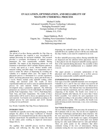
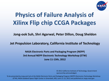
Am. J. Engg. & Applied Sci., 3 (1): 83-89, 2010was extensively used and in order to verify thesimulation result, the experimental work have beendone by conducting the thermal stress loading upon thereal package (Yi et al., 2000; Kar and Lo, 2006; SolidState Technology Association (JEDEC), 2004; Zhaoand Tay, 2003).In this study, the effect of different commercialunderfill material towards the reliability of HiCTE FlipChip Ceramic Ball Grid Array (FC-CBGA) underaccelerated temperature cycling (ATC) were studied.Dynamic Mechanical Analyser (DMA) and ThermalMechanical Analyser (TMA) analysis were conductedin-house to obtain the thermo-mechanical properties ofunderfill such as glass transition (Tg), Young’smodulus (E), Coefficient Thermal Expansion (CTE).FEA commercial software, ANSYS , used to predictthe effect of each underfill material to the packagewarpage condition, die back stress, die shear stress andsolder bump fatigue. The result from FEA was verifiedby conducting ATC test (-40 to 125 C) upon the actualpackage of HiCTE FC-CBGA according to JEDECJESD22-A104 condition G.MATERIALS AND METHODSUnderfill material properties: Five different types ofnew commercial underfills (namely as UFA, UFB,UFC, UFD, UFE) from five suppliers were selectedbased on their suitability for medium large die andfine pitch cu/low-k HiCTE FC-CBGA.Due to consistent test method compared with dataobtained from suppliers, material analysis using TMAand DMA were conducted in-house for obtainingunderfill thermomechanical properties (Yi et al., 2000).CTE and Tg of cured underfill were measured using aTA Instrument TMA. The cylindrical cured underfillwith 4.7 mm height was heated from -50 to 260 C witha heating rate of 10 C min 1.Young’s modulus of cured underfill weredetermined using TA Instrument DMA operated inrectangular tension mode. Cured underfill grinded intocubes with dimension about 15.0 2.5 1.20 mm andheated from -50 to 210 C using 10 C min 1 heating rate.For underfill materials, the definition of the mean oreffective CTE was used for the implementation insimulation is described by the following equation (Karand Lo, 2006):Effec t.CTE (Tg T1 )CTE1 (T2 Tg)CTE 2T2 T1was the underfill’s curing temperature ( 165 C), theeffective CTE for underfill were calculated (Kar andLo, 2006). The thermo-mechanical properties of allcomponents in the package are shown in Table 1 and 2.FEA modelling: To observe the effects towardwarpage package condition, die back stress, interfacialdie stress and underfill strain energy density, FEAanalysis were performed for global package withoutbumps. Meanwhile to observe the effect toward solderbump fatigue life, FEA analysis was performed forpackage slice model with two outer-most bumps. Bothsections were conducted using FEA commercialsoftware ANSYS.Global package model: The dimensions of the chipunder study were 15.0 12.0 0.75 mm and fullypopulated with high lead solder bumps (Pb90Sn10)with stand off 65 µm. The dimension of the HiCTEceramic substrate was 33.0 33.0 1.2 mm and theunderfill fillet height is considered as 100%. For thethermal stress effect in respect to the die back or corner,underfill and die interface and package warpage,analysis was carried out without bumps where linearelastic, time and temperature independent propertieswere assumed for all materials (Kar and Lo, 2006).Neglecting the bumps will not affect that much to theglobal model results. Due to symmetry, a quartersymmetric global model was used with correspondingboundary conditions and analyzed under acceleratedtemperature cycling (Kar and Lo, 2006). Figure 1 showsthe generated mesh of the model for global package.Table 1: Material properties for components of FC-CBGAComponent (ppm/ C)E (GPa) CTEPoisson ratioSilicon die131.502.800.27Solder bump (Pb90Sn10) 27.3024.500.35HiCTE ceramic substrate 85.3014.000.30UnderfillRefer to Table 2(1)where, T2 is the stress-free or reference temperature ofthe component being modelled. As T1 was -40 C and T2Fig. 1: A quarter symmetric model for HiCTE FPCBGA84
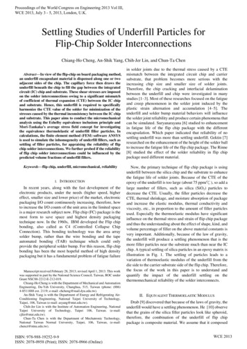
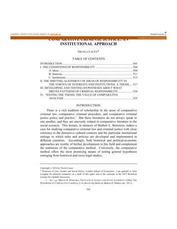
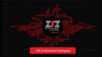
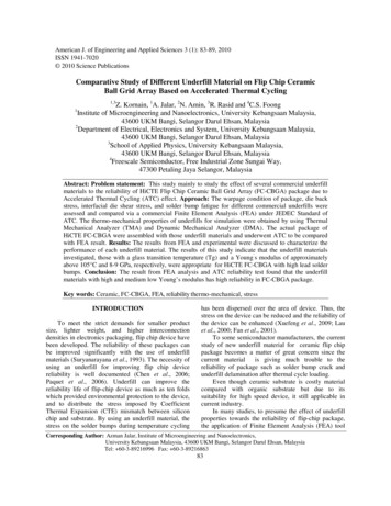
Am. J. Engg. & Applied Sci., 3 (1): 83-89, 2010Table 2: The thermo-mechanical properties for each underfill obtained from DMA and TMA analysis at -40 CSupplierMaterial codeCuring temperature (oC) Young modulusCTE 1/CTE 2/time (min)E (GPa)(ppm/ 2.80oHenkelUFD165 oC/90Fig. 2: A schematic of solder bump dimension for FEAFig. 3: A 3D slice model with mirror symmetry for twooutermost bumpFig. 4: HiCTE FC-CBGA package after assembly andcuredTemperature loading of the simulation based onJEDEC JESD22-A104 condition G. The dwell or rampperiod was l5 minutes and the temperature load wasramped up and down between the high of 125 C andthe low of -40 C with an increment of 10 C for eachload sub-step. The thermal load application wasassumed to be uniform throughout the FEA model(Solid State Technology Association (JEDEC), 2004).Eff. CTE(ppm/ 0102.40Solder joint fatigue model: Viscoplastic finite-elementsimulation methodologies were utilized to predictsolder ball joint reliability of the package under ATC.Due to the complex physics that encompass this type ofnon-linear transient finite element analysis, only a slicemodel with mirror symmetry and node-couplingboundary conditions were modelled in order tofacilitate reasonable model run time (Zhao and Tay,2003). Figure 2 shows a schematic geometry of the highlead bumps. The utilization of slice model as shown inFig. 3 assures that a worst-case situation was simulatedwhere two rows of bumps near die corners weremodelled based on Darveaux's modified Anand's (Zahn,2000). The explanations on solder joint fatigue lifeprediction methodology by Darveaux can be referredelsewhere (Xiaoyan and Wang, 2006; Darveaux, 2000).Accelerated temperature cycle reliability test: Inorder to compare with FEA result, the actual packagewas tested under ATC. Package dimension was similarto the package size for FEA. The package was a highspeed and high power microprocessor device fortelecommunication application. The die was developedwith CMOS 90 nm technology, internally engineeredlow-k dielectric and Polyimide (PI) passivation.Underfill was capillary dispensed to into the gapbetween die and substrate using Asymtek DS-9000Underfill Dispenser with preheating temperature at100 C and cured at certain temperature and time asshown in Table 2. The cured package then subjected to500 and 1000 cycles of -40 to 125 C ATC followingJEDEC JESD22-A104 condition G (Solid StateTechnology Association (JEDEC), 2004). Fig. 4 showsthe condition of package after assembly and cured.Package integrity after thermal stressing was assessedusing C-mode Scanning Acoustic Microscopy (CSAM) and cross sectioning inspection.RESULTSFinite element analysis: Package warpage comparisonand die back stress: During thermal cycle loading at 40C, the substrate contracts more than the die andbends into a convex shape causing a “frowning face”warpage (Wenge et al., 1998). Fig. 5 shows thewarpage of global package for UFA and Fig. 6 showsthe comparison of warpage value between all underfills.85
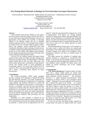
Am. J. Engg. & Applied Sci., 3 (1): 83-89, 2010Fig. 5: A FEA result of package warpage for UFA at 40 CFig. 6: Warpage comparison for different underfillFig. 8: A contour of principle stress at die for UFA at-40 CFig. 9: Highest shear stress occurred at die’s interfacialFig. 7: Comparison of maximum die back stress fordifferent underfillFig. 10: Comparison of maximum die corner shearstress for different underfillThe result of maximum principle stress for dieback as depicted in Fig. 7 shows that the UFC has givenhighest maximum stress at the die edge. Fig. 8 showsthe contour of die back stress for UFE demonstratingthe maximum stress concentrates at the area die’s edge.Solder bump fatigue life: The Von Mises stress(Sxy) and inelastic strain (W) after second cycle ofthermal loading for UFE are exhibited in Fig. 11a and brespectively while Fig. 11c shows the contour of solderplastic work density after second cycle of ATC at -40 Cfor UFE and the outermost solder bump has itmaximum value. The comparison among underfill forits effect to solder fatigue life is shown in Fig. 12.Die shear stress: High shear stress at -40 C, inducedbetween underfill and die interface lead to thedelamination in interfacial area and delaminate thefragile layer of low-k ILD located in the die (Yuko etal., 2002). Figure 9 shows that the highest shear stresscan be observed in the area of interface between die andunderfill and concentrated in the corner of the die.Figure 10 shows the comparison of die corner stress atmaximum value for different underfill materials.Package under ATC: The size of the samples for eachunderfill type was 30 based on industry requirement.Table 3 lists the reliability test results with allunderfills. Figure 13 shows the sample of failurecondition captured by C-SAM after ATC 1000 cycles.Figure 14 shows the cross-section of three outermostbumps for the failed sample of UFC.86
Am. J. Engg. & Applied Sci., 3 (1): 83-89, 2010(a)(b)(c)(d)Fig. 13: CSAM photo for after ATC 1000 cycles, (a)Ackage condition for UFA and UFD withoutdelamination, (b) Severe delaminationcondition for UFC, (c) Delamination conditionfor UFB, (d) Delamination condition for UFE(a)(b)(c)Fig. 11: (a) A contour of solder von mises stress in 2ndcycle at -40 C for UFE, (b) A contour of vonmises elastic strain in 2nd cycle at -40 C forUFE, (c) A Contour of solder plastic workdensity after second cycle for UFEFig. 12: Comparison of solder fatiguedifferent underfills after 2nd cyclelifeforTable 3: Result of ATC test for each underfill material. All underfillexhibits no voids and delamination before ATC testUnderfillUFAUFBUFCUFDUFEBefore ATC0/300/300/300/300/30ATC 500 cycles0/304/308/300/304/30ATC 1000 cycles 0/306/3020/300/304/30Fig. 14: Condition of solder crack in three outermostbump (left side of package) for UFCDISCUSSIONFinite element analysis: Package warpage comparisonand die back stress: Fig. 6 clearly shows that packagewith UFC has lowest warpage compared with others.Package with UFA and UFD have highest warpagevalue in the list. This condition can be attributed to thevalue of underfill’s Tg where the higher the Tg thehigher the warpage. This result agreed with workperformed by Wenge et al. (1998). As conclusion, thelower the warpage the better the reliability of thepackage can be achieved. It was reported that the higherthe stress, the die edge crack tends to occur with higherprobability (Fan et al., 2001). This agreed with theresult obtained in Fig. 7. Therefore, UFA has the lowestrisk to have the die edge crack. Figure 8 shows the areaof highly stress concentration at die’s edge where it cancontribute to crack.Die shear stress: At temperature of -40 C, high shearstress can be induced between underfill and dieinterface lead to the delamination in interfacial area and87
Am. J. Engg. & Applied Sci., 3 (1): 83-89, 2010delaminate the fragile layer of low-k ILD located in thedie (Yuko et al., 2002). This situation was of high riskto interface delamination due to high modulus andstiffness of the material (Yuko et al., 2002). UFA andUFD were predicted as the favorable candidate givinglowest impact to delamination since these materialhaving lower modulus under at -40 C during thermalcycling.Solder bump fatigue life: The solder joint viscoplasticstrain energy density accumulated per thermal cyclewas used to evaluate the fatigue life of bumpinterconnects and usually referred as the amount of“plastic work” accumulated per cycle (Zhao and Tay,2003; Zahn, 2000; Xiaoyan and Wang, 2006; Darveaux,2000). It clearly shown in Fig. 11 a and b that themaximum shear stress and inelastic strain energydensity occurs near the outermost edge of the solderbump. The lower the inelastic strain energy densityaccumulated per TC cycle ( W), the longer the thermalfatigue life of the solder joint (Zahn, 2000). The resultin Fig. 12 shows the UFA, UFD and UFE generated thelower solder work per cycle as compared with UFB andUFC. This condition induced lower solder fatigue lifefor all materials except UFC. According to previousresearcher (Xiaoyan and Wang, 2006), low Tg haspossible to induce solder bump crack, while high Tgcan protect the bump from tion between die and underfill were found asdominant failure in sample after ATC test (Chen et al.,2006). The open failure samples were extremely foundin UFC after ATC 500 cycles and 1000 cycles withhighest failure rate of 8/30 and 20/30 respectively asstated in Table 3. Meanwhile a few open failures foundin UFD and UFE after 500 and 1000 cycles. However,UFA and UFB passed ATC 500 and 1000 cycleswithout any failure. This outcome verified result in dieshear stress using FEA simulation which UFC haspossibility to generate highest die stress and induceddelamination particularly at corners of the die edge. Inthis case UFA and UFD have lowest risk upondelamination. The delamination in the package withUFB, UFC and UFE were found to be due to pooradhesion and high die shear stress(Suryanarayana et al.,1993; Chen et al., 2006). In principle, the package withUFC has the lowest thermo-mechanical reliabilitybecause it has low Tg and high CTE value (Lau et al.,2000). In the other hand, the package with the underfillmaterial of high Tg and low CTE value allowed thethermal and mechanical stresses to be well absorbedand distributed in the package (Chen et al., 2006).As depicted in Fig. 13, most of delaminationoccurred in the die’s corner. Package with UFC showssevere delamination at die corners as well as interfaceof underfill and solder mask of plastic substrate. Thisalso agreed with the simulation result discussed in dieshear stress section. To investigate failed samples forsolder bump, the package was subjected to crosssection and inspection under Scanning ElectronicMicroscope (SEM) as shown in Fig. 14. The solderbump cracking was found at the outermost bumplocation owing to the package with UFC has higherbump shear stress fatigue than others. Outermostbump 1 and 2 show crack while no crack occurred atthe third bump.No solder bump crack were found for the packagewith others underfill type. This observation agreed withprediction performance for solder fatigue as depicted inFig. 12. UFC was induced higher die shear stress at thedie corner than others. This implies the adhesive forcebetween die and underfill was not good enough(Chungpaiboonpatana and Shi, 2005). This was agreedwith simulation result presented in Fig. 8 where UFChad the highest die corner shear stress.For die back observation, no crack event wasobserved since all samples has low fillet height aftercured. The die back stress was more influenced by filletgeometry even though underfill material have some effecttoo. The effect from underfill material was reported as notcritical factor to die back reliability (Fan et al., 2001). Thefillet height and width affect the die back stress andpossible to induce the cracking in die edge.CONCLUSIONA study on the effect of different thermomechanical properties of underfill to the reliability ofHiCTE Flip Chip Ceramic Ball Grid Array (FC-CBGA)package due to Accelerated Thermal Cycling (ATC)was presented in this paper. It was found that UFCwhich supplied from demonstrated worst impact tosolder crack and delamination when thermal cyclingstress loaded into the package due to low Tg, high CTEand high Young’s modulus. Two favourable candidateswhich demonstrated good reliability after using FEAanalysis and reliability test were UFA and UFD. Bothmaterials produced no delamination and solder bumpcrack after ATC reliability test. The material with highTg and medium low of Young’s modulus resultinggood protection to solder bump crack and die/underfillinterfacial failure. This study suggested that theunderfill materials with a glass transition temperature(Tg) and a Young’s modulus of approximately above105 C and 8-9 GPa, respectively, were suitable88
Am. J. Engg. & Applied Sci., 3 (1): 83-89, 2010properties value in order to pass the industry standardof ATC test for HiCTE FC-CBGA.ACKNOWLEDGEMENTThe researchers would like to express theirappreciation to Freescale Semiconductor for theirsupport in experimental job and heartfelt gratitude to DrKar Shim Wei from Freescale Semiconductor for hisconsultation to the modeling work. Also would like tothank Microscopy Lab of UKM for their help in crosssection and SEM analysis.REFERENCESChen, K.M., D.S. Jiang, N.H. Kao and J.Y. Lai, 2006.Effects of underfill materials on the reliability oflow-k flip chip packaging. Microelect. 5.001Chungpaiboonpatana, S. and F.G. Shi, 2005 AdvancedHiCTE ceramic flip-chipping of 90nm Cu/low-kdevice: A novel material, package structure, andprocess optimization study. J. Elect. Mater.,34: 977-993.http://cat.inist.fr/?aModele afficheN&cpsidt 16947867Darveaux, R., 2000. Effect of simulation methodologyon solder joint crack growth correlations.Proceeding of the 50th IEEE ElectronicsComponent and Technology Conference, May 2124, IEEE Xplore Press, Las Vegas, USA.,pp: 1048-1058. DOI: 10.1109/ECTC.2000.853299Fan, X.J., H.B. Wang and T.B. Lim, 2001. Investigationof underfill delamination and cracking in flip chipmodule under thermal cycle loading.IEEE.Trans. Comput. Pack. Technol., 24: 84-90. DOI:10.1109/6144.910806Kar, W.S. and W.Y. Lo, 2006. Solder fatigue modelingof flip-chip bumps in molded packages. Proceedingof the 31th International Electronic ManufacturingTechnology, IEEE Xplore Press, Nov. 8-6,Putrajaya, Kuala Lumpur, pp: 109-114. DOI:10.1109/IEMT.2006.4456441Lau, J.H., W.S. Lee and C. Chang, 2000. Effects ofunderfill material properties on the reliability ofsolder bumped flip chip on board with imperfectunderfill encapsulants. IEEE. Trans. Comput. Pack.Technol., 23: 323-333. DOI: 10.1109/6144.846771Paquet, M., M. Gaynes, E. Duchesne, D. Questad, L.Belanger and M. Sylvestre, 2006. Underfillselection strategy for pb-free, low-K and fine pitchorganic flip chip applications. Proceeding of the56th Electronic Components and TechnologyConference, IEEE Xplore Press, July 5-7, 645870Solid State Technology Association (JEDEC), 2004.Joint industry standard: Temperature Cycling.JEDEC-JESD22-A104C May 2005, pp: 1-10.Suryanarayana, D., T.Y. Wu and J.A. Varcoe, 1993.Encapsulants used in flip-chip packages. IEEETrans. Comput. Hybrids Manufactur. Technol.,16: 858-862.http://cat.inist.fr/?aModele afficheN&cpsidt 4056611Wang, L. and C.P. Wong, 2000. Recent advances inunderfill technology for flip-chip, ball grid array,and chip scale package applications. Conference ofInternational Symposium on Electronic Materialsand Packaging, Nov. 30-Dec. 2, IEEE XplorePress, Hong Kong, pp: 224-231. DOI:10.1109/EMAP.2000.904159Wenge, Z., D. Wu, B. Su, S.A Hareb, Y.C. Lee, andB.P. Masterson, 1998. The effect of underfill epoxyon warpage in flip chip assemblies. IEEE. Trans.Comput. Pack. Manufactur. Technol. A., 21: 0705481.pdf?arnumber 705481Xiaoyan, L. and Z. Wang, 2006. Thermo-fatigue lifeevaluation of SnAgCu solder joints in flip chipassemblies. J. Mat Proces. Tech., 183: 6-12. DOI:10.1016/j.jmatprotec.2006.09.010Xuefeng, O., S.W. Hoa, Y.Y. Onga, L.C. Waia, K.Vaidyanathana and Y.K. Lim, 2009. UnderfillSelection methodology for fine pitch Cu/low-kFCBGA packages. Microelect. Reliabil., 49: 150-162.http://cat.inist.fr/?aModele afficheN&cpsidt 21172778Yi, H. et al., 2000. Thermal characterization of anepoxy-based underfill material for flip chippackaging. Thermochimica Acta, 40: 1-8.http://cat.inist.fr/?aModele afficheN&cpsidt 1443851Yuko, S., K. Harada and H. Fujioka, 2002. Study ofpackage warp behavior for high-performance flipchip BGA. J. Microelect. Reliabil., 43: 465-471. DOI:10.1016/S0026-2714(02)00294-9Zahn, B.A., 2000. Comprehensive solder fatigue andthermal characterization of a silicon based multichip module package utilizing finite elementanalysis methodologies. Proceeding of 9thInternational ANSYS Conference and Exhibition,Aug. 28-30, Pittsburgh, USA., pp: o, B. and A.A. Tay, 2003. Simulation of fatigue lifeof solder ball joints of an ultra-fine-pitch waferlevel package. Proceeding of the 5th ElectronicsPackaging Technology Conference, Dec. 10-12,IEEE Xplore Press, Singapore, pp: 683-686.http://ieeexplore.ieee.org/xpl/freeabs all.jsp?arnumber 127160689
densities in electronics packaging, flip chip device have been developed. The reliability of these packages can be improved significantly with the use of underfill materials (Suryanarayana et al ., 1993). The necessity of using an underfill for improving flip chip device reliability is well documented (Chen et al ., 2006;