Transcription
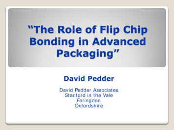
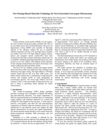
Proceedings of the World Congress on Engineering 2013 Vol III,WCE 2013, July 3 - 5, 2013, London, U.K.Settling Studies of Underfill Particles forFlip-Chip Solder InterconnectionsChiang-Ho Cheng, An-Shik Yang, Chih-Jer Lin, and Chun-Ta Chen Abstract—In view of the flip-chip on board packaging method,an underfill encapsulant material is dispensed along one or twoadjacent sides of the chip. The capillary force then draws theunderfill beneath the chip to fill the gap between the integratedcircuit (IC) chip and substrate. These shear stresses are imposedon the solder interconnections owing to a significant mismatchof coefficient of thermal expansion (CTE) between the IC chipand substrate. Hence, this underfill is required to specificallyharmonize the CTE value of the solder for minimization of thestresses caused by the thermal inconsistency between the IC chipand substrate. This paper aims to conduct the micromechanicalanalysis using the Eshelby equivalence inclusions principle andMori-Tankaka’s average stress field concept for investigatingthe equivalence thermolelastic of underfill filler particles. Incalculations, the finite element method (FEM) software ANSYSis used to simulate the inhomogeneity of underfill fillers, such assettling of filler particles, for appraising the reliability of flipchip solder interconnections. We further probed if the reliabilityof flip chip solder interconnections could be influenced by thepredicted volume fractions of underfill fillers.Keywords—flip chip, underfill, micromechanical, reliabilityI.INTRODUCTIONIn recent years, along with the fast development of theelectronic products, under the needs (higher speed, highereffect, smaller size and lower price) of the market, electronicpackaging I/O count continuously increasing, therefore, howto increase the I/O counts of the unit area in the limited spaceis a major research subject now. Flip chip (FC) package is themost form to save space and highest density packagingtechnique now. In the 1960s, IBM developed the Flip chipbonding, also called as C4 (Controlled Collapse ChipConnection). This bonding technology was the area arraysolder bump, rather than the wire bonding and the tapeautomated bonding (TAB) technique which could onlyprovide the peripheral solder bump. For this reason, flip chipbonding has been the most hopeful method of high densitypackaging but it has a fundamental problem of fatigue failureManuscript received February 28, 2013; revised April 1, 2013. This workwas supported in part by the National Science Council, Taiwan, ROC underGrant NSC88-2212-E-212-019.Chiang-Ho Cheng is with the Department of Mechanical and AutomationEngineering, Da-Yeh University, Changhua, 515, Taiwan (phone: (886)4-8511888 ext. 2119; e-mail: chcheng@mail.dyu.edu.tw).An-Shik Yang is with the Department of Energy and Refrigerating AirConditioning Engineering, National Taipei University of Technology,Taipei, 106, Taiwan (e-mail: asyang@ntut.edu.tw).Chih-Jer Lin is with the Institute of Automation Engineering, NationalTaipei University of Technology, Taipei 106, Taiwan. (e-mail:cjlin@ntut.edu.tw).Chun-Ta Chen is with the Department of Mechatronic Technology,National Taiwan Normal University, Taipei, 106, Taiwan, (e-mail:chenct@ntnu.edu.tw).ISBN: 978-988-19252-9-9ISSN: 2078-0958 (Print); ISSN: 2078-0966 (Online)in solder joints due to the thermal stress caused by a CTEmismatch between the integrated circuit chip and carriersubstrate, that problem becomes more serious with theincreasing chip size and smaller size of solder joints.Therefore, the chip cracking and interfacial delaminationbetween the underfill and chip were investigated in manystudies [1–3]. Most of these researches focused on the fatigueand creep phenomenon in the solder joint induced by theplastic strain alternation and accumulation [4–5]. Theunderfill and solder bump material behaviors will influencethe solder joint reliability and produce certain phenomena thatcan be simulated. Suryanarayana [6] studied to enhancementin fatigue life of the flip chip package with the differentencapsulation. Which paper indicated that reliability of nosettling underfill was more than settling underfill. Gektin [7]researched on the enhancement of the height of the solder ballto increase the fatigue life of the flip chip package. The Rinne[8] studied the effect of the solder reliability in flip chippackage used different material.Now, the primary technique of flip chip package is usingunderfill between the silica chip and the substrate to enhancethe fatigue life of solder joints. Because of the CTE of theepoxy of the underfill is too large (about 75 ppm/ ), so add alarge number of fillers, such as silica (SiO2) particles todecrease the CTE. Usually, the filler particles decrease theCTE, thermal shrinkage, and moisture absorption of packageand increase the elastic modulus, thermal conductivity andviscosity, etc., in proportion to the amount of filler particlesused. Especially the thermoelastic modulus have significantinfluence on the thermal stress and strain of flip chip packageand thus the understanding about the effect of shape, kind, andvolume percentage of filler on the above material constants isvery important. Additionally, because of the law of gravity,the underfill will produce a settling phenomenon that is themore filler particles near the substrate much than near the ICchip. A typical settling of silica particles in an epoxy matrix isillustration in Fig. 1. The settling of particles leads to avariation of thermoelastic modulus of the underfill from thedie side to the carrier substrate side of the flip chip. Therefore,the focus of the work in this paper is to understand andquantify the impact of the underfill settling on thethermomechanical reliability of the solder interconnects.II. EQUIVALENT THERMOELASTIC MODULUSDrab [9] discovered that because of the laws of gravity, theunderfill would have a settling phenomenon. He [10] observethat the grains of the silica filler particles look like spheroid,therefore, the combination of the underfill of flip chippackage is composite material. We assume that it composedWCE 2013
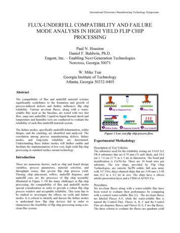
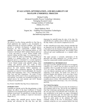
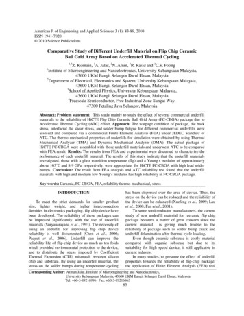
Proceedings of the World Congress on Engineering 2013 Vol III,WCE 2013, July 3 - 5, 2013, London, U.K.of homogenous and continuous matrix fill the discontinuousfiller. General the matrix of the underfill of the flip chippackage is pure epoxy, the primarily inclusion of filler is thesilica which is a isotropic material (material property show asTable I), with the theory of the micromechanical this studycomputes out the equivalent thermolelastic modulus of theunderfill by the concept of the equivalent inclusion principleof the Eshelby [11] and the average stress field of theMori-Tankaka [12]. Which the effective elastic modulus C and effective coefficient of thermal expansion α areexpression as follows: [13](1)α α0 f1 A H (I f1 B) [ f1 B (C0 C1 ) C1 (α1 -α0 )] f1 ( A H S I) C0 1 C1 (α1 -α0 )Where A (I C-10 C1 )substratesubstratesubstrateABCPARTICLE VOLUME FRACTION FILL IN UNDERFILL(2)0.30.50.7Yonug’s 440.3380.326Coefficient of ThermalExpansion ( ppm/ )41.926.514.5(3)F [ (I - S A) f1 (S - I) A ]-1(4) 1B (S I) A H(5)III. FINITE ELEMENT SIMULATE(6)A schematic drawing of diagonal cross-section of flip chippackage composed of FR-4 substrate, silicon chip, underfilland solder bumps is shown in Fig. 2. [14] The numericalmodel was two-dimensional (2D) with the plane strainassumption and only one-half of the cross-section wasmodeled due to geometry symmetry. The silica chip is 3.51mm in length, 0.64 mm in thickness. The substrate material isFR-4, which is 5.82 mm in length, 0.7 mm in thickness. Thesolder material is assumed 63wt%Sn/37wt%Pb, which is 0.16mm in diameter, 0.15 mm in height, and 0.52 mm in pitch.The underfill consider settling phenomenon in analysis,therefore the finite element model of underfill divided into theabove layer and the below layer two layers. If the underfill hasnot settling phenomenon, the above layer and the below layerhave the equivalent material properties, which are thecomposite material of the silica fill in the epoxy. Its materialproperties are the effective material properties of compositematerial calculate by the micromechanical. If the underfill hassettling phenomenon, the above layer is pure epoxy, the belowlayer are composite material. Table III [15] lists the materialproperties using in the analysis in the study. The finiteelement meshes for the overall numerical model is show asFig. 3. The symmetrical boundary conditions were appliedalong the left edge of the model. The left bottom corner wasconstrained in the vertical direction to prevent body motion.The material property of the solder ball is elastic-plastic,which is relation with the temperature. Fig. 4 illustrates therelations of different temperatures effects on the stress-straincurves. Other materials are all linear elastic and isotropic,and independent of in variety temperatures. In accordancewith standard of fatigue test of JESD22-A104-A [16] ofJEDEC (Joint Electron Device Engineering Council). Theloadings of temperature are form - 40 to 125 in theanalysis. Fig. 5 shows the thermal cycle numerical analysishistory in this study. The thermal cycle temperature rangedfrom 40 to 125 with a ramp rate of 8.25 /min and adwell time of 10 min at the peak temperature.The capital English boldface letter represent fourth ordertensor; the lower case Greece boldface letter represent secondtensor; subscripts 0, 1 represent two types of differentmaterials of matrix (pure epoxy) and filler particles (silica)respectively; f1 represent the volume fraction of the matrix forfiller particles; C and α represent elastic modulus andcoefficient of thermal expansion respectively; S and Irepresent Eshelby tensor and fourth order identity matrixrespectively; Eshelby tensor depend on the configuration ofinclusions. Appendix is the Eshelby tensor when inclusionsconfiguration are sphere.The underfill will produce the settling phenomenon by theeffect of the law of gravity. Therefore we consider threedifferent types of underfill of silica filler particles fill in pureepoxy. First, the filler particles are diffused in matrixhomogenously which without settling phenomenon, alsoconsider the filler particles with the phenomenon of settling.The beginning is 20% pure matrix and 80% compositematerial of underfill, and then is 50% pure matrix and 50%composite material of underfill, illustrate in Fig. 1. Assumethe filler particles are homogenous distribute in pure epoxy.In view of the silica filler particles distributed in the volumefractions of 0.3, 0.5 and 0.7 respectively, we can compute theeffective material properties of the underfill as presented inTable II. This study examines the parameters of three types ofparticles in three different volume fractions, respectively.TABLE ITHE MECHANICAL PROPERTY OF UNDERFILLPureEpoxySilicaIC chipFig. 1. Three different types of underfill of silica filler particles fill in pureepoxy. A: without settling phenomenon, B: 80% settling height, C: 50%settling height. 1-1H (I S A)IC chipTABLE IITHE EFFECTIVE MECHANICAL PROPERTY OF THE DIFFERENT FILLERC* C0 [I f1 A F]-1*IC chipYonug’s Modulus( MPa)Poisson’sRatioCoefficient of ThermalExpansion( ppm/ )25000.3575710000.20.6ISBN: 978-988-19252-9-9ISSN: 2078-0958 (Print); ISSN: 2078-0966 (Online)WCE 2013
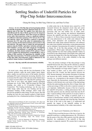
Proceedings of the World Congress on Engineering 2013 Vol III,WCE 2013, July 3 - 5, 2013, London, U.K.IV. THEORY OF RELIABILITYTABLE IIITHE MECHANICAL PROPERTY OF THE MATERIAL OF FLIP CHIPYonug’sCoefficient ofPoisson’sModulusThermal ExpansionRatio( MPa)( ppm/ )IC chip1310000.32.8FR-4 substrate220000.281863Sn37Pb363000.3525solderFlip chip package receives a loading of the periodic thermalcycle, which is caused the materials tension and compressionstress over and over to failure of thermal fatigue. The fatiguefailure is takes the largest plastic shear strain place, usually.Hence, we obtained the largest plastic shear strain of thesolder using the finite element analysis software ANSYS by atemperature cycle in the study. And the Coffin-Manson[16-18] relationship was also employed to predict the fatiguelife of the flip chip package : Nf C p(7)Where N f represent the number of cycle to failure of thesolder connections, and p represent inelastic strain range.For 63Sn37Pb solder, Solomon fit his data at –50, 35 and 125 into the relation of Coffin-Manson and obtained theaverage values as C 1.2928 and 1.96 . The appliedinelastic strain range in equation (7) is replaced by the cornerplastic shear strain to serve as a simplified reliability estimate[19-23].Fig. 2. The dimensions of the numerical model.V. RESULTS AND DISCUSSIONFig. 3. Finite element meshes for the overall numerical model.90OT -65 C8070OT 0 CStress(MPa)60OT 25 C5040OT 75 C30OT 100 C20OT 125 C100012345678910Strain(%)Fig. 4. Temperature-dependent stress–strain curves of solder ball.150100OTemperature( C)This study used the micromechanical theory in conjunctionwith the finite element analyses software ANSYS to simulateand investigate the underfill effect on the flip chip packagingreliability. Applying the 2-D analysis model, the shear strainis the primarily factor causing the fatigue failure. Hence, weadopted the range of the plastic shear strain as an indicator topredict the reliability of the solder ball. Because the fatiguefailure is usually occurred at the outmost region of solder balls,we focus on the crucial issue where the solder ball connectswith other materials, as shown in Fig. 6. The points A and Dare expressed as the junction place of the IC chip and underfillwith the points C and F specified accordingly as the junctionplace of the substrate and underfill, whereas the points B andE are denoted as the settling place of underfill.500020406080100120-50Time(min)Fig. 5. Thermal cycle history of the numerical analysis of this study.ISBN: 978-988-19252-9-9ISSN: 2078-0958 (Print); ISSN: 2078-0966 (Online)First, the settling phenomenon is not observed when thevolume fraction of silica filler particles for the underfill is 0.5.Figure 7 illustrates the plastic shear strain of 0.5 silica volumefraction without settling phenomenon occurred at 1800 and3600s. Afterward, in Fig. 8 showing the plastic shear strainrange for all measurement points, it can be found that thecurve A has the largest plastic shear strain range. When thevolume fraction of the silica is 0.5, the associated reliability ofthe solder ball is 19577 cycles. Table IV demonstrates thepredicted reliability of different volume fractions of the silicafiller particles in the underfill. When the settling phenomenonof filler particles takes place, it is observed that the silica fillerparticles volume fraction of the underfill is 0.5. Figures 9 and10 present the plastic shear strain diagram of the solder ballfor 80% to settling height and the plastic shear strain rangediagram for all measurement points, respectively. In addition,Figs 11 and 12 show the plastic shear strain diagram of thesolder ball for 50% to settling height and the plastic shearstrain range diagram for all measurement points. Tables V and6 are the predicted solder ball reliability for different volumefractions of silica filler particles in the underfill with theWCE 2013
settling process of filler particles taken place. The fatiguefailure places of the solder balls also take place at the point A.When the silica filler particles in the underfill is 80% settlingheight, the solder ball reliability is about over 2,000 cycles.When the silica filler particles in the underfill are 50% settlingheight, the solder ball reliability is about over 1,000 cycles.Besides, in Figs. 13 and 14, we discover the effect of silicavolume fraction on the settling phenomenon of underfill fordetermining the solder ball reliability. With no finding of thesettling phenomenon of underfill, an increase in the volumefraction of silica filler particles can enhance the solder ballreliability. On the other hand, if the settling phenomenon ofunderfill takes the place, the growing silica volume fractiontends to reduce the solder ball reliability.plastic shear strainProceedings of the World Congress on Engineering 2013 Vol III,WCE 2013, July 3 - 5, 2013, London, U.K.Time (sec)Fig. 8. The plastic shear strain range for all measurement points of 0.5 silicavolume fraction and without settling phenomenonIC chipADBSolderETABLE IVPREDICTED RELIABILITY OF THE SILICA FILLER PARTICLES AT WITHOUTSETTLING PHENOMENONFCSubstrateVolume FractionPlastic Shear .508966501957740414Fig. 6. The measuring points of the solder ballT 1800 secT 1800 secT 3600 secT 3600 secFig. 7. The plastic shear strain of 0.5 silica volume fraction and withoutsettling phenomenon at 1800 and 3600 sec.ISBN: 978-988-19252-9-9ISSN: 2078-0958 (Print); ISSN: 2078-0966 (Online)Fig. 9. The plastic shear strain of 0.5 silica volume fraction and 80% settlingheight at 1800 and 3600 sec.WCE 2013
plastic shear strainplastic shear strainProceedings of the World Congress on Engineering 2013 Vol III,WCE 2013, July 3 - 5, 2013, London, U.K.Time (sec)Time (sec)Fig. 10. The plastic shear strain range for all measurement points of 0.5 silicavolume fraction and 80% settling height.Fig. 12. The plastic shear strain range for all measurement points of 0.5 silicavolume fraction and 50% settling height.TABLE VPREDICTED RELIABILITY OF THE SILICA FILLER PARTICLES UNDER 80%TABLE VIPREDICTED RELIABILITY OF THE SILICA FILLER PARTICLES UNDER 50%SETTLING HEIGHTSETTLING HEIGHTVolume FractionPlastic Shear Strain 24221142038Volume FractionPlastic Shear Strain 13310701036Reliability(cycles)1000001000010000T 1800 sec0.20.40.60.8Volume FractionFig. 13. The silica volume fraction and reliability relations of withoutsettling.50% seetling height80% seetling 0000.20.40.60.8Volume FractionT 3600 secFig. 14. The silica volume fraction and reliability relations of 80% and 50%settling heightFig. 11. The plastic shear strain of 0.5 silica volume fraction and 50%settling height at 1800 and 3600 sec.ISBN: 978-988-19252-9-9ISSN: 2078-0958 (Print); ISSN: 2078-0966 (Online)WCE 2013
Proceedings of the World Congress on Engineering 2013 Vol III,WCE 2013, July 3 - 5, 2013, London, U.K.[7]VI. CONCLUSIONThis study has discovered the significant influence of thevolume fraction of underfill filler particles on the solder ballreliability for determination of the fatigue life of the flip chippackage. The inducible conclusion from the analyses is givenas follows:1) With no finding of the settling event of the underfill, thereliability of solder balls can be substantially improvedby adding the silica volume fraction.2) As the settling phenomenon of the underfill occurs, theincreases of the silica volume fraction and the ration ofthe above pure epoxy layer to the underfill can decreasethe solder ball reliability.[8][9][10][11][12][13]Therefore, it is very important to avoid the happening of thesettling event of the underfill for enhancement of the flip chippackage reliability.[15]APPENDIXFor spherical inclusion, the components of Eshelby’stensor Sijkl are given by7 5 015 1 0 5 0 1S1122 S 2233 S3311 15 1 0 4 5 0S1212 S 2323 S3131 15 1 0 [14]S1111 S 2222 S3333 [16][17][18](A-1)[19][20]where 0 is the Poisson’s ratio of matrix (epoxy).[21]ACKNOWLEDGMENTThis paper represents part of the results obtained under thesupport of the National Science Council, Taiwan, ROC(Contract No. [4][5][6]V. Gektin, B.C. Avram and J. Ames, Coffin-Manson Fatigue Model ofUnderfill Flip-Chips, IEEE Trans. CPMT, part A, Vol. 20, 1997, pp.317-326.G.A. Rinne, P.A. Magill, W.C. Machon, J.D. Mis, R.T. Park and J.W.Baggs, Solder Alloy Selection for Flip Chip on Board, InternationalSymposium on Advanced Packaging Materials, 1998, pp. 118-122.K. Darbha, J. H. Okura and A. Dasgupta, Impact of Underfill FillerParticles on Reliability of Flip-Chip Interconnects, IEEE Trans. CPMT,part A, Vol. 21, 1998, pp. 275-279.Y. He, B. E. Moreira, A. Overson, S. H. Nakamura, C. Bider and J. F.Briscoe, Thermal Characterization of an epoxy-based UnderfillMaterial for Flip Chip Packaging, Thermochimica Acta Vol. 357-358,2000, pp. 1-8.J. D. Eshelby, The Determination of the Elastic Field of an EllipsoidalInclusion and Related Problems, Proc. R. Soc., Vol. A241, 1957, pp.376-396.T. Mori and K. Tanaka, Average Stress in Matrix and Average ElasticEnergy of Materials with Misfitting Inclusions, Acta. Metall., Vol. 21,1973, pp. 571-574.C. H. Chen and C. H. Cheng, Effects Elastic Moduli of MisorientedShort-Fiber Composites, Int. J. Solids and Structures, Vol. 33, 1996, pp.2519-2539.S. Lin, J. Wang, D. Zou, X. He and Z. Qian, Resolving DisplacementField of Solder Ball in Flip-Chip Package by Both Phase ShiftingMoire Interferometry and FEM Modeling, IEEE ElectronicComponents and Technology Conference, 1998, pp. 1345-1353.J. H. Lau, Solder Joint Reliability of Flip Chip and Plastic Ball GridArray Assemblies Under Thermal, Mechanical, and VibrationalConditions, IEEE Trans. CPMT, part B, Vol. 19, No. 4, 199, pp.728-735.W. W. Lee, L. T. Nguyen and G. S. Selvaduray, Solder Joint FatigueModel: Review and applicability to chip scale packages,Microelectronics Reliability, Vol. 40, 1999, pp. 231-244.J. H. Lau, Flip Chip Technologies, New York, McGraw-Hill, Inc,1995.H. D. Solomon, Fatigue of 60/40 solder, IEEE Transact. Components,Hybrids, Manufact. Technol., Vol. 9, 1986, pp. 423-432.J. Wang, W. Ren, D. Zou and S. Liu, Effect of Cleaning andNon-Cleaning Situations on the Reliability of Flip-Chip Packages,IEEE Transactions on Components and Packaging Technology, Vol.22, No.2, 1999, pp. 221-228.A. Schubert, R. Dudek, B. Michel and H. Reichi, Materials Mechanicsand Mechanical Reliability of Flip Chip Assemblies on OrganicSubstrates, International Symposium on Advanced PackagingMaterials, 1997, pp. 106-109.S. Rzepka, F. Feustel, E. Meusel, M. A. Korhonen and C. Y. Li, TheEffect of Underfill Imperfections on the Reliability of Flip ChipModules: FEM Simulations and Experiments, IEEE ElectronicComponents and Technology Conference, 1998, pp. 362-370.Z. Qian, M. Lu, W. Ren and S. Liu, Fatigue Life Prediction ofFlip-Chips in Terms of Nonlinear Behaviors of Solder and Underfill,IEEE Electronic Components and Technology Conference, 1999, pp.141-148.J. H.L. Pang, T. I. Tan and S. K. Sitaraman, Thermo-MechanicalAnalysis of Solder Joint Fatigue and Creep in a Flip Chip On BoardPackage Subjected to Temperature Cycling Loading, IEEE ElectronicComponents and Technology Conference, 1998, pp. 878-883.H. Reichl, A. Schubert, Topper, Reliability of flip chip and chip sizepackages, Microelectron. Reliab. Vol. 40, 2000, pp. 1243–1254.L. Chen, Q. Zhang, G. Wang, X. Xie, Z. Cheng, The effect of underfilland its material models on thermomechanical behaviors of a flip chippackage, IEEE Trans. Adv. Packag. Vol. 24, 2001, pp. 17–24.S.K. Sitaraman, R. Raghunathan, C.E. Hanna, Development of virtualreliability methodology for area-arrray device used in implantable andautomotive application, IEEE Trans. Comp. Packag. Technol. Vol. 33,2000, pp. 452–461.J. Wang, D. Zou, Z. Oian, W. Ren, S. Liu, Effect of non-cleaningsituations on the reliability of flip-chip packages, in: Proceeding of theIEEE Electronics Components and Technology Conference, 1998, pp.211–219.J.H. Lau, S.W. Ricky, C. Chang, Effect of underfill material propertieson the reliability of solder bumped flip chip on board with imperfectunderfill encapsulants, IEEE Trans. Comp. Packag. Technol. Vol. 23,2000, pp. 323–333.D. Suryanarayana, R. Hsiao, T.P. Gall, and J.M. McCreary,Enhancement of flip-chip fatigue life by encapsulation, IEEE Comp.,Hybrids, Manufact. Technol., Vol.14, 1991, pp. 218-223.ISBN: 978-988-19252-9-9ISSN: 2078-0958 (Print); ISSN: 2078-0966 (Online)WCE 2013
Abstract—In view of the flip-chip on board packaging method, an underfill encapsulant material is dispensed along one or two adjacent sides of the chip. The capillary force then draws the underfill beneath the chip to fill the gap between the integrated circuit (IC) chip and substrate. These shear stresses are imposed