Transcription
Understanding Voids inFlip Chip InterconnectsEric D. PerfectoGLOBALFOUNDRIESTel: s presentation is available only to CPMT members, any reproductionrequires written permission from the presenter.The slides included here do not represent an endorsement of GLOBALFOUNDRIES on thetechnologies presented, they were included by the author for educational purposes only.Eric Perfecto – 2016 CPMT Webinar1
Outline1st and 2nd Level Packaging IntroductionVoids- Ball Drop (BGA and u-BGA) Voids- Solder Screen Voids- Surface Voids- Fabrication Voids- Stress Driven Voids- Thermal Stress Voids- Electromigration Stress VoidsTesting MethodsSummaryEric Perfecto – 2016 CPMT Webinar2
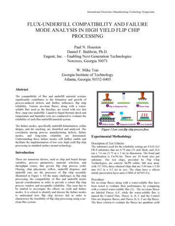
1st and 2nd Level Packaging Technology ElementsChip-Package InteractionCTE stresses, low K BEOLChip- 1st level interconnectHeat sinksCu, Al, complex designC4(solder) UnderfillHeat spreaders1st level packagesorganic, ceramicpassive, activeBGAPrinted Wiring Board (PWB)1st-2nd level interconnectThermal InterfaceMaterialspaste, gels, metalssolder, mechanicalChip Carrier Options:CeramicEric Perfecto – 2016 CPMT WebinarLaminatesInterposer3
Bumping General DimensionsCu-PillarUBM: 10 – 80 um30 50100uBGAC480 – 150 um150200BGA0.35–0.9 mm0.20 – 0.4 mm2503004005001300Flip chip interconnect pitch (um)ElectroplatingPaste ScreeningPreformed Solder BallsEric Perfecto – 2016 CPMT Webinar4
Flip Chip Bump Capacity ForecastCu Pillar is the fastest growing segment of the flip chip portfolio.Eric Perfecto – 2016 CPMT WebinarSource: 2015 Yole Flip Chip Report5
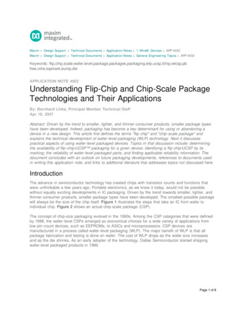
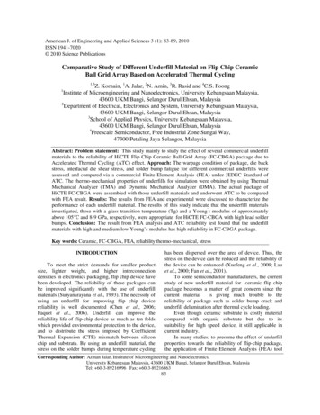
Interposer AssemblyTop Chipu-Cu PillarC4 SAC solder2interposerCu/Ni/ Au padsUBMC4 SAC solderCu padsSAC solder CoinedNi/Au or Cu OSPC41LaminateTop ChipHighCTEinterposerPossible Assembly :Join Laminate to interposerUnderfill 1Join Top Chip to interposerUnderfill 2BGA SAC attachModule TestUnderfillUnderfill LaminateUnderfill5X reflows5X reflowsBall Grid Array (BGA)UnderfillSolder Paste,and/or Imm Ag or CuPWBEric Perfecto – 2016 CPMT Webinar6
Sn-Ag-Cu Solder Ternary Phase /agcusn.htmlEric Perfecto – 2016 CPMT Webinar7
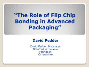
Intermetallic Formation onFlip Chip ApplicationSputtered Ni Cu UBMNi(Cu,Ni)6Sn5ChipCu6Sn5SnAg solderLaminateSnAg solderSnAg solder6.7 um Cu6Sn5Ni/Cu is a very effective barrier for Pb-freeapplications – typically used on the chip side.Thick Cu or solder on laminate side.Ni-Solders results in Ni3Sn4 Intermetallic (IMC)Eric Perfecto – 2016 CPMT Webinar3.0 umCu3SnCu8
BGA and u-BGA Void TypesSPSPPS SolderP Landing PadR. Aspandiar , presentation at SMTA Chapter meeting (2005)R. Aspandiar, “Voids in Solder Joints,” SMTA Journal, V19 I4, 2006Eric Perfecto – 2016 CPMT Webinar9
BGA: Shrinkage and Pinhole VoidsShrinkage Voids:Hot tear voids are formedduring the solidification ofthe solder during BGAjoining. Increase cooling ratecan minimize this defect.Pinhole Microvoids:Top viewPinhole Microvoids:1 to 3 um in diametercrevices in the plated Cumatrix of the BGA receivingpad can entrap fluidsresulting on void formationabove IMC at ball attach.x-sectionCuRaiyo F. Aspandiar, “Voids in Solder Joints,” SMTA Journal, V19, Issue 4, 2006Eric Perfecto – 2016 CPMT Webinar10
BGA: Microvia VoidsRaiyo F. Aspandiar, “Voids in Solder Joints,”SMTA Journal, V19, Issue 4, 2006Microvia Voids:Via cavities within the BGA landing pad results on poor solder paste coverage,entrapping air. Large bubbles are attached to the UBM and do not escape. Nosolder paste fill results in increased voids propensity.Plugged ViaInverted ViaMitigation:- Eliminate the via topography: dog-bone, plugged or inverted microvias.- Increase via size for better fill- Optimize surface finishing for solder wetting and better fill.- On chip to laminate joining, solder paste is first reflowed and coined(mechanically flattened) prior to chip joining.Eric Perfecto – 2016 CPMT Webinar11
Voids in Flip Chip Stencil PrintingUBMFabricationSolderScreenSolder PasteReflowFluxCleanStencilWaferUBMT. D. Ewald, et. al., “VoidFormation During ReflowSoldering,” 2012 ECTCSolder paste voids can be form during reflow due to solder dewetting.Flux volume, Flux evap. temperature, paste volume, pad surface area, padsurface finish and reflow environment, all play a role in void formation.Eric Perfecto – 2016 CPMT Webinar12
Solder paste Flux Selection and pEric Perfecto – 2016 CPMT Webinar13
BGA: Planar Voids Root Cause and Solution 10umEric Perfecto – 2016 CPMT WebinarD. Cullen, et. al., "Eliminating Microvoid Risk Via an Optimized Surface FinishProcess,” International Conf. on Lead-free Soldering, Toronto, CA, May 2006.14
Pattern Electroplating ProcessElectroplated Pb-free ProcessSputter SeedUBM and C4 – As platedウエハ( )iIResist ApplyDefine Patternウエハ( )iIElectroplateUBM (Cu, Ni) SnAg solderウエハ( )iSIC4 – Post ReflowLResist Stripウエハ( )iISSeed EtchiSウエハ( )L ISReflowウエハ( )iEric Perfecto – 2016 CPMT WebinarI15
Electroplating Induced Interfacial (Planar) VoidsPost Reflow x-section:Sn/AgVoidsVoidsIMCCuIMCTop view SEM of expose IMC after thesolder was chemically etched:Voids are between IMC and solderEric Perfecto – 2016 CPMT WebinarC. L. Arvin, E. Perfecto, et. al, “Interfacial Voids at the Under BumpMetallurgy and Solder Interface,” ECS in Boston, MA, Fall 2011.16
Incorporation of Species at SnAg Platingwhich contribute to Void FormationEric Perfecto – 2016 CPMT WebinarC. L. Arvin, E. Perfecto, et. al, “Interfacial Voids at the Under BumpMetallurgy and Solder Interface,” ECS in Boston, MA, Fall 2011.17
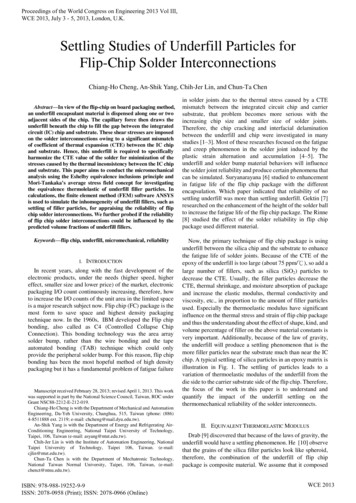
Electroplating Induced Interfacial (Planar) Voids4593.2.16.pro4593.3.17.proAg AtomicConcentration (%)Atomic Concentration (%)100Experimental matrix:90New vs Old SnAg plating bath- Plate pure metal (Ni, Cu,)80- Immerse in SnAg bath (5 secor 150sec)70Time prior toelectroplating6050- Repeat with old SnAg platingbath (5sec or 150 sec)Run 2 – old 15sRun 3 – old 150sRun 4 – new 15s4030- Depth profile using AugerRun 5 – new 150s20100050100150200250300Sputter Depth (Å )350400450500Sputter Depth (A)- Bath age impacts the on-set of interfacial voids- Propensity for Ag to corrode Ni (zero @ 150 sec) Cu (25A at 5 sec / 110A at 150 sec)- Propensity to form room temperature intermetallics with solder Cu NiEric Perfecto – 2016 CPMT WebinarC. L. Arvin, E. Perfecto, et. al, “Interfacial Voids at the Under BumpMetallurgy and Solder Interface,” ECS in Boston, MA, Fall 2011.18
Electroless Ni(P) UBMElectroless Ni(P) Etch ProcessIncomming SubstarteCeramic or Organic laminatei(Electropless Ni(P) AuHigh Temp Diffusei(i(Solder Deposition bySolder Screen, C4NP, BallDropP-rich layerCCCUpon joining the Sn-based solder to the electroless Ni(P) UBM pad, the Ni reacts withthe solder forming a Ni3Sn4 intermetallic. This reaction results in the formation of acrystalline Ni3P layer also known as P-rich layer between the IMC and the Ni(P). Microvoids form on this layer.NiV, NiW and NiSi UBM barrier have the same problem as Ni(P). This is known asreaction-assisted crystallization.Eric Perfecto – 2016 CPMT Webinar19
HTS: Electroless Ni(P) voidsSn3.5%Agaged at 150Cfor 1000hrsVoids are generated in the crystalline Ni3P layer after thermal stress.- ENEC/OSP (Electroless Ni(P) Electroless Copper OSP) results in a robust(Cu, Ni)6Sn5 IMC which reduces the Ni consumption and so the Ni3P formation.M. L. Huang, et al, “Morphology and growth kinetics of intermetallic compounds in solid-state interfacial reaction of electroless NiP with Snbased lead-free solders,” Journal of Electronic Materials, January 2006Young-Doo Jeon, et. at., “Thin Electroless Cu/OSP on Electroless Ni as a Novel Surface Finish Joints,” 2006 ECTCEric Perfecto – 2016 CPMT Webinar20
HTS Stress and Kirkendall Voids10 days of 125 C aging3 days of 125 C agingSolderSolderCu6Sn5Cu3SnCu6Sn5Cu3SnCuCu40 days of 125 C agingSolderCu6Sn5Tz-Cheng Chiu, et. al., “Effect of ThermalAging on Board Level Drop Reliability forPb-free BGA Packages,” 2004 ECTCEric Perfecto – 2016 CPMT WebinarCu3SnCu21
Kirkendall Voids and IMC VoidsKirkendell Voids - Mechanism 1:- During Joining of Sn solders with Cu surface the Cu6Sn5 intermetallic crystallizes,along Cu layer, stopping further dissolution of Cu.- Also a thin intermetallic layer, Cu3Sn, forms between Cu and Cu6Sn5.- During thermal aging, atomic vacancies are left by Cu atoms migration from the Cuside – which are not filled by the Sn atoms.- These vacancies coalesce into the so called Kirkendall voids at Cu - Cu3Sn interface,and in Cu3Sn layer.- Voids can increase to form a discontinuous layer.Impurities - Mechanism 2:- Impurities in the plated Cu resulting in morphology and diffusion changes and voidgeneration.Vol. Reduction - Mechanism 3:- Volume reduction and therefore voids during the conversion of Cu6Sn5 to Cu3Sn.Mitigation:- Replacing the Cu OSP layer with a Ni(P) or Ni(P)/Cu layer.- Solder additives such as Ni, Bi, Zn.- Increase purity of plated Cu.Eric Perfecto – 2016 CPMT Webinar22
Effect of %Ag in Cu3Sn IMCs GrowthSn-0.5Cu (Q&500h)Sn-1.0Ag-0.5Cu (Q&500h) Sn-3.0Ag-0.5Cu (Q&500h)After thermal aging at 150 C/500 hrs, the size of Cu6Sn5 grains remains stable.10 µmCu6Sn5Kirkendall voidsCu3SnincreasedecreaseCu3Sn layer was reduced with increase of Ag% in the solder, but the thickness oftotal IMCs was similar. (Kirkendall voids reduction)Increase in %Ag, reduces the Cu6Sn5 grain sizeMoon Gi Cho, et. al., “Effect of Ag on Ripening Growth of Cu6Sn5 Grains,” 2010 ECTCEric Perfecto – 2016 CPMT Webinar23
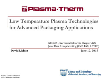
Kirkendall Void in Cu3Sn IMCStack: 14Cu/15SnAgT0 500 hrs HTS@150C, UFT0, no UF,Cu6Sn5T0 1000 hrs HTS @150C, UFCu3SnT0 250C, 30 min, UFT0 250C, 30 min 1000hrs HTS @150C, UFThe size and number of Kirkendall voids increased with 500 hrs at 150 C HTS andremained stable at 1000hrs HTS.Full conversion of intermetallic prior to HTS testing mitigated the Cu3Sn IMC and theamount of Kirkendall voids at that intermetallic.Eric Perfecto – 2016 CPMT WebinarH. Zhang, E. Perfecto, et.al., “An Effective Method for Full Solder Intermetallic CompoundFormation and Kirkendall Void Control in Sn-base Solder Micro-joints,” 2015 ECTC24
Microvoiding Vs. Kirkendall VoidsWhereandare the intrinsic diffusion coefficients ofCu and Sn, respectively.If the voids are solely due to diffusion effects, the voids willconcentrate at theinterface.S. Kumar, et. al., “Microvoid Formation at Solder-Cooper InterfacesDuring Annealing,” JEM V40, No.12, 2011Eric Perfecto – 2016 CPMT Webinar25
Voids Generation vs Impurities in Plated CuFrom P. BorgersenSuppressor: polyethylene glycol (PEG)Bath additives: Brightener: Bis-(3-sulphopropyl)-disulfide (SPS)Accelerators: Thiol (-SH) or Sulfonate (-SO3)Eric Perfecto – 2016 CPMT WebinarY. Liu, L. Yin, et. at , IEEE Trans. Comp. Pack. Techno. 33,127 (2010)26
Cu Impurity Voids and UBMFrom P. BorgersenEric Perfecto – 2016 CPMT WebinarL Yin and P. Borgersen, J. Mater. Res. 25, 455 (2011)27
Voids Understanding: Cu Plating Bath AgeBath Temperature and current density can also modulate void formation.From P. BorgersenEric Perfecto – 2016 CPMT WebinarL Yin, et al., “Towards a better Understanding of the Effect of CuElectroplating Process Parameters on Cu3Sn Voiding,” JEM, V41, No.2, 201228
Solder Additives Mitigates IMC VoidsJoints Aged at 150 C for 1000 hrsCuSolderSACSAC 0.6%ZnAlso Ni and Co addition into the solder reduce the Cu3Sn and voids.Eric Perfecto – 2016 CPMT WebinarI. DeSousa, et. al., “The Influence of Low Level Doping on the Thermal Evolution ofSAC Alloy Solder Joints with Cu Pad Structures,” ECTC 200629
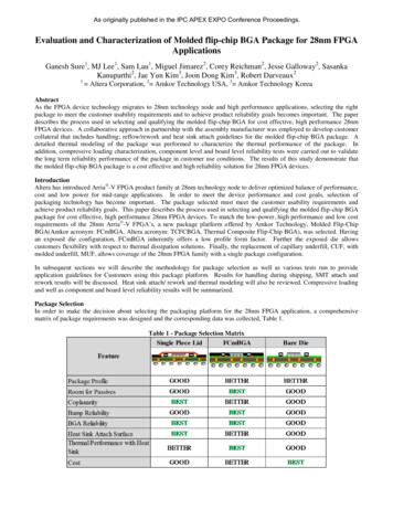
Thermal Stress Voids ThroughIMC Volume ReductionVolume decrease @ IM formation:6Cu 5SnCu6Sn5 5%3Cu SnCu3Sn 7.6 %Soaking condition 260C 45minCu-PillarUn-constrained solderCu-PillarIM- full conversionNiSnAg solder HeightConstrained by underfillVoids and impurities migrate to the IMC centerEric Perfecto – 2016 CPMT Webinar30
Electromigration failsIMC spallinginto the solderVoid atIMC-SolderinterfaceM. Lu, et. al., “Comparison of ElectromigrationPerformance for Pb-free Solders and Surface Finishes,”2008 ECTCCurrent crowding:Highest current densityoccurs at the point wherethe UBM meets theBEOL wiringChia-Ming Tsai, PhD ThesisEric Perfecto – 2016 CPMT Webinar31
Testing MethodsBall ShearDestructiveChip PullDestructiveBall PullDestructiveX-ray (2D)Non-DestructiveX-ray tomography (3D)Non-DestructiveX-sectionDestructiveEric Perfecto – 2016 CPMT Webinar32
Individual Solder Shear Test% Voids caninfluence shearforce (and failuremode).Eric Perfecto – 2016 CPMT WebinarC. Y. Lin, et. al., “Failure Mode Analysis of Lead-free Solder,” 2008 ICEPT-HDP33
Chip Pull TestingPurpose– Destructive test to check for structure and process robustness.– Chip is attached to the organic carrier and pulled with an ingstrontool. Fail interfaces and pull strength is examined.Sample Chip Pulls (destructive)– Inspect for solder joints: good wetting, contact non-wets, non-contact non-wets– Large I/O chips require support substrate to prevent sample breakage.Failure modesIn the BEOLEric Perfecto – 2016 CPMT WebinarWithin the UBMAt the IntermetallicIn the solder34
Individual Bump Pull TestDage tool Testing Setup: Test speed- 1000mm/s (high speed ball pull) Land force: 10 gram.Typical force: 60 gfFailed interfaces:At solderAt BEOL (pulled out)At UBM or intermetallicNew addition is automatic wire placement and wire pull.Eric Perfecto – 2016 CPMT Webinar35
3D X-Ray (X-Ray CT) Computed Tomography3D X-Ray (X-Ray CT)- 2D images are mathematicallysuperimposed and processed to obtain athree dimensional map of the sample- Virtual cross-sections at any givelocation. Resolution is limited by:- position wrt the source to freely rotatewithout hitting it.- the spot size of the x-ray source3D-CTM. Pacheco and D. Goyal, “Detection and Characterization ofDefects in Microelectronic Packages and Boards by Means ofHigh-Resolution X-Ray CT,” 2011 ECTCEric Perfecto – 2016 CPMT Webinar36
X-Ray 2D Inspection2D X-ray is the most common monitor tool for in-line solder void monitoring.- BGS /CSP Package to substrate criteria:Michael A. Previti, et. al., “Four Ways toReduce voids in BGA/CSP Package toSubstrate Connections,” Cookson ElectronicsEric Perfecto – 2016 CPMT Webinar37
X-section Method for Void DetectionX-section options:1) Mechanical polish for large voids2) Focus Ion beam (FIB) for small p / CALCEEric Perfecto – 2016 CPMT Webinar38
Summary-Pb-free solder interconnect in Flip Chip, Cu-Pillar, CSP, andBGA continues to grow each year. And one of the major defecttypes in Pb-free applications is solder voids.-There are many root caused for solder voids: fabrication,assembly and life stress. Most of them are understood andstructure or process changes are available to produce a morerobust Pb-free interconnect.-By looking at the voids size and location, a good prediction ofits origin can be estimated.-Additionally, there are several testing methods that are usedto characterized and monitor the fabrication and assemblyprocesses to control any process drift and void formation.Eric Perfecto – 2016 CPMT Webinar39
Thank you.Eric Perfecto – 2016 CPMT Webinar
Flip Chip Interconnects. Eric Perfecto - 2016 CPMT Webinar 2 Outline 1st and 2nd Level Packaging Introduction Voids - Ball Drop (BGA and u-BGA) Voids . Underfill Top Chip interposer Top Chip UBM C4 SAC solder Cu pads SAC solder Coined Underfill 1 2 PWB Solder Paste, and/or Imm Ag or Cu.