Transcription
Product Data SheetPS-00400June 2002Micro MotionSeries 1000 and 2000 Transmitterswith MVD Technology!www.micromotion.com
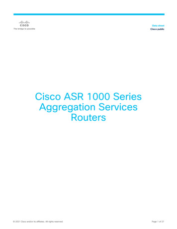
Micro Motion Series 1000 and 2000 Transmitterswith MVD TechnologyScalable architectureThe new approach tosensor electronics Only Micro Motion combines new MVDTechnology with a modular architecture thatredefines sensor electronics. That meansmultivariable digital processing that’s scalable forany flow application. MVD Technology gets yourmost basic – or most complex – application upand running quicker, easier and more costeffectively than ever before.You asked for it and Micro Motion has delivered.Series 1000 and 2000 transmitters allow you tochoose the functionality you want. Series 1000transmitters are perfect for applications thatrequire single variable measurement. For moredemanding applications, Series 2000 transmittersmeasure multiple variables simultaneously, haveadditional output and digital communicationoptions, and can be used in custody transferapplications.MVD TechnologyMVD Technology makes your Micro Motionflowmeter work smarter. Front-end digitalprocessing dramatically reduces signal noise andgives you faster response time compared toanalog devices. Innovative MVD Technology alsoenables multiple variable measurement anddiagnostics never before possible. And this is justthe beginning.What happens when you put Micro Motion’sMVD Technology together with the Series 1000and 2000 transmitters?Only four wiresOnly MVD Technology allows you to: Measure multiple variables Choose integral or remote mounting with astandard twisted, shielded 4-wire signalcable Identify and resolve problems easily withbuilt-in smart diagnostics Choose transmitter capabilities based onyour application’s needs Upgrade transmitter functionalityas neededWhat’s the bottom line of MVD Technology?Reducing costs in your bottom line throughimproved process consistency andmaximized uptime.2Series 1000 and 2000 TransmittersApproved forhazardous areas
Clean, noise-freedigital signals thatimprovemeasurementperformanceSeries 1000 flow measurement transmitterFor applications requiring only mass flow orvolume flow measurementSeries 1000 transmitters are ideal for flowapplications where only a single variable isneeded at any given time. Series 1000transmitters feature a milliamp and afrequency/pulse output, and HART or Modbus digital communications.Delivering a suite of power-packedstandard featuresSeries 1000 transmitters can output one of thefollowing variables:All Series 1000 and 2000 transmitters offer: Mass flow rate Volume flow rate Class I, Division 1/Zone 1 local operatorinterface to: View process variables View meter status at a glance View and acknowledge alarms Start, stop, and reset transmitter totalizers Zero flowmeter Perform output simulation tests Change measurement units Assign variables to outputs Scale outputs Set RS-485 communication options Interface functions can be customized andpassword protected Compact, integral mounting to sensor with360 degrees of rotation Cost-effective, hassle-free, 4-wire remotemounting to sensor Simple start-up with virtually no specialprogramming requirements Digital communications Easy-to-access diagnostics: meter status,process issues, and moreSeries 2000 Multivariable TransmitterFor applications requiring simultaneousmonitoring of multiple flow variablesSeries 2000 transmitters are designed specificallyfor applications where multiple variables areneeded simultaneously. Series 2000 transmittersfeature a milliamp and a frequency/pulse output,plus HART, Modbus, FOUNDATION Fieldbus, andProfibus-PA digital communications.Series 2000 transmitters can simultaneouslyoutput multiple variables, including: Mass flow rate Volume flow rate Density Temperature Drive gainSeries 1000 and 2000 Transmitters3
Series 1000 and Series 2000 TransmittersOffering options tailored to meet yourapplication needsDiscrete batch controlCustody transferSimple discrete batch control is easy using theModel 2700 transmitter. The frequency output canbe configured as a discrete output, using batchtargets entered from a host control system or fromthe local display. If additional inputs or outputs arerequired, the Series 3000 transmitter/controllershould also be considered.Series 2000 transmitters feature physical securityfor custody transfer applications such as bottlefilling, CNG dispensing, and vehicle loading andunloading. Micro Motion Coriolis meters providelegal trade accuracies for a wide range of fluidswithout the need for upstream and downstreamstraight runs and without the need for externalcompensation. Custody transfer based on massflow eliminates many of the problems associatedwith volumetric technologies: Coriolis meters haveno moving parts, are not affected by seasonalvariations in quantities delivered due totemperature changes, and can eliminate re-workand waste by providing the correct amount ofproduct every time.Petroleum measurementThe Model 2700 with the petroleum measurementsoftware option software option can calculate: Base density CTL (the effect of temperature on a liquid) Gross volume at standard temperature Flow weighted average temperatureFast response time Flow weighted average density (observedgravity)Series 1000 and 2000 transmitters offer as astandard feature a selectable response time forthe analog output and frequency output. Thenormal response mode uses the maximumamount of digital signal processing (DSP) and a20 Hz update rate for the selected processvariable. The special response mode uses a100 Hz update rate with slightly reduced noiserejection. Micro Motion Coriolis sensors withSeries 1000 and 2000 transmitters are an idealchoice for applications that require fast, accuratemeasurements. MVD DSP provides excellentrepeatability with batch times as low as 1 secondin duration, and eliminates process variations dueto density and temperature changes.One instrument can now be used to measurecorrected volume flow and corrected density,eliminating the need for a densitometer, reducingmaintenance, and lowering your capitalinvestment. No calibration or recalibration fordifferent density fluids is required. The softwareuses API MPMS Chapter 11.1 for GeneralizedPetroleum, Generalized Crude Oil, Lubricants,and other fluids with a known thermal coefficientof expansion to calculate base density from theflowing density and flowing temperature.4Series 1000 and 2000 Transmitters
Series 1000 and 2000 functional specificationsElectrical connectionsInput and output connectionsThree pairs of wiring terminals for transmitter outputs.Screw terminals accept one or two solid conductors, 14 to12 AWG (2.5 to 4 mm2); or one or two stranded conductors,22 to 14 AWG (0.34 to 2.5 mm2).Power connectionOne pair of wiring terminals accepts either AC or DCpower.One internal ground lug for power-supply ground wiring.Screw terminals accept one or two solid conductors, 14 to12 AWG (2.5 to 4 mm2); or one or two stranded conductors,22 to 14 AWG (0.34 to 2.5 mm2).Service port connectionTwo clips for temporary connection to the service portInput/output signalsAll transmittersOne 4-wire sensor signal input connection with ground,intrinsically safeNon-intrinsically safe output HART/Modbus transmitters(output option code A, see page 9 for output option codedescriptions)One active 4–20 mA outputNot intrinsically safeIsolated to 50 VDC from all other outputs and earthgroundMaximum load limit, 600 ohmsSeries 1000 can report mass flow or volume flow; Series2000 can report mass flow, volume flow, density,temperature, or drive gainOutput is linear with process from 3.8 to 20.5 mA, perNAMUR NE43 (June 1994)One active or passive frequency/pulse outputNot intrinsically safeCan report mass flow or volume flow, which can be usedto indicate flow rate or totalFor Series 1000, if mA output is not assigned to flowrate, the frequency output acts as a discrete outputFor Series 2000, frequency output is independent ofmA outputScalable to 10,000 HzMaximum output of 30 VDC max., 24 VDC typicalInternal 2.2 kohm pull-up, sinking up to 500 mA at 30VDC maximumOutput is linear with flow rate to 12,500 HzNon-intrinsically safe configurable output transmittersfor Series 2000 transmitters (output options codes Band C, see page 9 for output option code descriptions)Two active 4–20 mA outputsNot intrinsically safeIsolated to 50 VDC from all other outputs and earthgroundMaximum load limit: mA1 — 820 ohms;mA2 — 420 ohmsSeries 2000 can report mass flow, volume flow, density,temperature, or drive gainOutput is linear with process from 3.8 to 20.5 mA, perNAMUR NE43 (June 1994)Two active or passive frequency/pulse outputsNot intrinsically safeCan report mass flow or volume flow, which can be usedto indicate flow rate or totalOutputs are electrically isolated but not independent(see custody transfer note below)Scalable to 10,000 HzInternally powered to 15 VDC 3%Externally powered 3–30 VDC max., internal 2.2 kohmpull-up, sinking up to 500 mA at 30 VDC maximumOutput is linear with flow rate to 12,500 HzTwo discrete outputsNot intrinsically safeCan report event 1, event 2, event 1 and 2, flow switch,forward/reverse flow, calibration in progress, or faultMaximum sink capability is 500 mAOne discrete inputCan report none, start mechanical zero, reset masstotal, reset volume total, reset corrected volume total,or reset totalsCustody transfer using double pulse frequency outputThe transmitter can be configured for two frequencyoutputs on channels B and C. The frequency outputs arenot independent – they are identical in frequency. Theoutput on channel C can be phase-shifted 0, 90, or 180degrees from the output on channel B. The direction of flowcan be inferred from the direction of phase shift, and theamount of flow can be determined by reading channel B. Inaddition, channel C can output zero to indicate a faultcondition.Series 1000 and 2000 Transmitters5
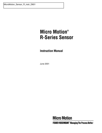
Series 1000 and 2000 functional specifications continuedIntrinsically safe transmitters (output option code D, seepage 9 for output option code descriptions)One intrinsically safe passive 4–20mA output (two withSeries 2000)Maximum input voltage, 30 VDC, 1 watt maximumMaximum current 300 mAMaximum load limits, see chart belowSeries 1000 can report mass flow or volume flow; Series2000 can report mass flow, volume flow, density,temperature, or drive gainOutput is linear with process from 3.8 to 20.5 mA, perNAMUR NE43 (June 1994)mA Output Load Resistance ValueRmax (Vsupply - 12)/0.0023**If communicating with HART a minimum of 250 ohms and 17.75V supply is needed1000External resistor 2141618202224262830Supply voltage (volts)One intrinsically safe passive output, configurable asfrequency, pulse, or discrete outputMaximum input voltage, 30 VDC, 0.75 watt maximumMaximum current 100 mAMaximum load limit, see chart belowCan report mass flow or volume flow, which can be usedto indicate flow rate or totalFor Series 1000, output is dependent on mA output; forSeries 2000, output is independentScalable to 10,000 HzOutput is linear with flow rate to 12,500 HzFrequency Output Load Resistance ValueRmax (Vsupply - 4)/0.003*Rmin (Vsupply - 25)/0.006*Absolute minimum 100 ohms for Vsupply 25.6 volts10000External resistor 0001000057911131517192123Supply voltage (volts)6Series 1000 and 2000 Transmitters252729Fieldbus and PROFIBUS-PA transmittersOne FOUNDATION fieldbus H1 or PROFIBUS-PA outputFOUNDATION fieldbus and PROFIBUS-PA wiring isintrinsically safe with an intrinsically safe powersupplyManchester-encoded digital signal conforms to IEC1158-2.
Series 1000 and 2000 functional specifications continuedDigital communicationsPower supplyAll transmittersOne service port can be used for temporary connectiononly.Uses RS-485 Modbus signal, baud rate of 38.4 kilobaud,one stop bit, no paritySelf-switching AC/DC input, automatically recognizessupply voltage.HART or intrinsically safe HART output (output optioncodes A, B, C, or D)HART Bell 202 signal is superimposed on the primarymilliamp output, and is available for host system interface.Frequency 1.2 and 2.2 kHzAmplitude 0.8 V peak-to-peak1200 baudRequires 250 to 600 ohms load resistanceInstallation (Overvoltage) Category II, Pollution Degree 2HART/Modbus transmitter (output option Code A)One RS-485 output can be used for direct connection to aHART or Modbus host system. Accepts baud ratesbetween 1200 baud and 38.4 kilobaud.Fieldbus transmittersTransmitters are registered with the Fieldbus Foundation,and conform to the Foundation fieldbus H1 protocolspecification.Input frequency from sensorMass flow20 HzVolume flow20 HzDensity20 HzTemperature1 HzComplies with low voltage directive 73/23/EEC per IEC1010-1 with amendment 2The transmitter fieldbus circuit is passive, and draws itspower from the fieldbus segment. Current draw from thefieldbus segment is 11.5 mA.AC power85 to 265 VAC, 50/60 Hz, 5 watts typical, 8 watts maximumDC power18 to 100 VDC, 5 watts typical, 8 watts maximumAt startup, transmitter power source must provide aminimum of 1.5 amperes of short-term current at aminimum of 18 volts at the transmitter’s power inputterminalsMinimum 22 VDC with 1000 feet of 18 AWG (300 meters of0.8 mm2) power-supply cableFuseIEC 127-1.25 fuse, slowblowAnalog Input Function BlocksCycle timehost dependentUpdate rate50 millisecondsRefresh ratehost dependentPROFIBUS-PA transmittersTransmitters are registered with the PROFIBUSOrganization, and fulfill the requirements of thePROFIBUS-PA Profile for Process Control Devices.Input frequency from sensorMass flow20 HzVolume flow20 HzDensity20 HzTemperature1 HzAnalog Input Function BlocksCycle timehost dependentUpdate rate50 millisecondsRefresh ratehost dependentSeries 1000 and 2000 Transmitters7
Series 1000 and 2000 functional specifications continuedEnvironmental limitsAmbient temperature limitsOperating–40 to 140 F (–40 to 60 C)Storage–40 to 140 F (–40 to 60 C)Note: Display responsiveness decreases, and display maybecome difficult to read, below –4 F (–20 C). Above 131 F(55 C), some darkening of display might occur.ATEX and UL approvals require limiting ambienttemperature to below 131 F (55 C).Humidity limits5 to 95% relative humidity, non-condensing at 140 F (60 C)Vibration limitsMeets IEC 68.2.6, endurance sweep, 5 to 2000 Hz, 50 sweepcycles at 1.0 g.Environmental effectsEMI effectsSeries 1000 and 2000 transmitters conform to NAMURNE21 (August 1998 German and May 1999 English).Series 1000 and 2000 transmitters meet EMC directive 89/336/EEC per EN 50081-2 (August 1993) and EN 50082-2(March 1995), and EN 61326 Industrial.Ambient temperature effectOn analog outputs 0.005% of span per CHazardous area classificationUL and CSAAmbient temperature is limited to below 131 F (55 C) for ULcompliance.TransmitterClass I, Div. 1, Groups C and D. Class II, Div. 1, Groups E,F, and G explosion proof (when installed with approvedconduit seals). Otherwise, Class I, Div. 2, Groups A, B, C,and D.OutputsProvides nonincendive sensor outputs for use in Class I,Div. 2, Groups A, B, C, and D; or intrinsically safe sensoroutputs for use in Class I, Div. 1, Groups C and D or ClassII, Div. 1, Groups E, F, and G.8Series 1000 and 2000 TransmittersATEXAmbient temperature is limited to below 131 F (55 C) forATEX compliance.HART/Modbus and configurable input/output transmitters(output option codes A, B, or C)All models are CE 0575II 2GFlameproof when installed with approved cable glands:with displayEEx d [ib] IIB H2 T5without displayEEx d [ib] IIC T5Increased safety when installed with approved cableglands:with displayEEx de [ib] IIB H2 T5without displayEEx de [ib] IIC T5Fieldbus, PROFIBUS-PA, and IS output transmitters (outputoption codes D, E, and G)All models are CE 0575II 2(1)GFlameproof when installed with approved cable glands:with displayEEx d [ia/ib] IIB H2 T5without displayEEx d [ia/ib] IIC T5Increased safety when installed with approved cableglands:with displayEEx de [ia/ib] IIB H2 T5without displayEEx de [ia/ib] IIC T5
Series 2000 Transmitters with Configurable Inputs and OutputsSeries 2000 transmitters with configurable IOfunctionalityThe Series 2000 transmitter with configurable inputs andoutputs is designed to increase transmitter flexibility andreduce the number of transmitter variations required ininventory. The table below shows the various configurationoptions that can be produced with the configurable IO outputoption. When output code B is selected, the transmitter ships withchannels assigned to default values. When output code C is selected, the transmitter is customconfigured prior to shipment.ChannelTerminalsConfiguration optionsDefault variable assignmentPowerA1 and 2mAO with Bell 202/HART (only)mass flowinternalB3 and 4 mAO (default) mAO — densityinternal FO FO — mass flowinternal or external(1) DO DO — fwd/rev flowinternal or external FO (default)(2) FO — mass flowinternal or external DO DO — flow switchinternal or external DI DI — noneinternal or externalC(1)Channel assignments for Series 2000transmitters with configurable IO (outputoption codes B and C)5 and 6The user must supply power when a channel is set to external power.(2)When configured for two frequency outputs (dual pulse), both outputs are generated from the same signal. The outputs areelectrically isolated but not independent.Series 1000 and 2000 Transmitters9
Series 2000 with FOUNDATION fieldbusSeries 2000 fieldbus software functionalitySeries 2000 Foundation fieldbus software is designed topermit remote testing and configuration of the transmitterusing the DeltaV Fieldbus Configuration Tool, or otherFoundation fieldbus compliant hosts. The illustration belowshows how the Coriolis sensor signal is channelled throughthe flowmeter to the control room and the Foundation fieldbusconfiguration device.Transducer blockThe transducer block holds the data from the Coriolis sensor.It includes information about the sensor type, sensorconfiguration, engineering units, calibration, damping, anddiagnostics.Resource blockThe resource block contains physical device information,including available memory, manufacturer identification, typeof device, and features.Function blocksThe Analog Input (AI) function block processes themeasurement from the Coriolis sensor and makes it availableto other function blocks. It also allows filtering, alarmhandling, and engineering unit change. Each of the fourSeries 2000 AI blocks can be assigned to one variable fromthe five available: mass flow, volume flow, density,temperature, and drive gain.Integrator blockThe integrator block provides functionality for the transmittertotalizers. The flow variable (mass or volume) can be selectedand reset.Diagnostics and serviceSeries 2000 transmitters automatically perform continuousself diagnostics. Using the transducer block, the user canperform on-line testing of the transmitter and sensor.Diagnostics are event driven and do not require polling foraccess.Block diagram for Series 2000 transmitters with FOUNDATION fieldbusFOUNDATION fieldbus compliantcommunications stackIntegrator blockFlow totalizersResource blockPhysical deviceinformationFunction blocksAI1, AI2, AI3, AI4Transducer blockCoriolis sensor signal processing(equations, diagnostics)10Series 1000 and 2000 Transmitters
Series 1000/2000 performance specificationsSensorProcess VariableAccuracyRepeatabilityELITEflow(1)liquids and slurriesgas(2) 0.10% of rate(3) 0.35% of rate(3) 0.05% of rate(4) 0.20% of rate(4)densityCMF010Pothers 0.002 g/cc ( 2.0 kg/m3) 0.0005 g/cc ( 0.5 kg/m3) 0.001 g/cc ( 1.0 kg/m3) 0.0002 g/cc ( 2.0 kg/m3)temperature 1 C 0.5% of reading in C 0.2 Cflow (liquid only)(1) 0.15% of rate(3) 0.05% of rate(4)density (liquid) 0.002 g/cc ( 2.0 kg/m3) 0.001 g/cc ( 1.0 kg/m3)temperature 1 C 0.5% of reading in C 0.2 Cflow(1)liquids and slurriesgas 0.20% of rate(3) 0.70% of rate(3) 0.10% of rate(4) 0.35% of rate(4)density (liquid) 0.002 g/cc ( 2.0 kg/m3) 0.001 g/cc ( 1.0 kg/m3)temperature 1 C 0.5% of reading in C 0.2 Cflow(1)liquidgas(5) 0.5% of rate(3) 0.75% of rate(3) 0.25% of rate(4) 0.50% of rate(4)densitynot rated for densitytemperature 1 C 0.5% of reading in CT-SeriesF-SeriesR-Series 0.2 C(1)Flow accuracy includes the combined effects of repeatability, linearity, and hysteresis. All specifications for liquids are based onreference conditions of 68 to 77 F (20 to 25 C) and 15 to 30 psig. Specifications for gas are based on air at 60 F (15.5 C) and1000 psig (70 bar), unless otherwise noted.(2)CMF400 sensors are not rated for gas.(3)When flow rate is less than [zero stability/(base accuracy percentage/100)], accuracy equals [(zero stability/flow rate) x 100]%of rate.(4)When flow rate is less than [zero stability/(base accuracy percentage/100)], repeatability equals [½(zero stability/flow rate) x100]% of rate.(5)R200 sensors are not rated for gas.Series 1000 and 2000 Transmitters11
Model 1700 and 2700 physical specificationsField-mount housingNEMA 4X (IP67) epoxy painted cast aluminum housing.Terminal compartment contains output terminals, powerterminals and service-port terminals. The output terminalsare physically separated from the power- and service-portterminals.The electronics compartment contains all electronicsand the standard display.The sensor compartment contains the wiring terminalsfor connection to the core processor on the sensor.Screw-terminal on housing for chassis ground.Cable gland entrances are either 1/2”-14 NPT or M20 x 1.5female conduit ports.MountingModel 1700 and 2700 field-mount transmitters areavailable integrally mounted to Micro Motion T-Series,R-Series, and F-Series sensors. They may also beremotely mounted to any Micro Motion sensor. See thesensor Product Data Sheet for details and restrictions.Remote-mount transmitters include a mounting bracket,and require standard 4-wire twisted, shielded signalcable, up to 1000 feet (300 meters) in length, betweenthe sensor and the transmitter. Hardware for installingthe transmitter on the mounting bracket is included.Remote-mount transmitters with a 9-wire signal cablebetween the sensor and the transmitter have amaximum cable length of 60 feet (20 meters). Hardwarefor installing the transmitter on the supplied mountingbracket is supplied.The transmitter can be rotated on the sensor or themounting bracket, 360 degrees, in 90-degreeincrements.12Series 1000 and 2000 TransmittersInterface/displaySegmented 2-line display with LCD screen with opticalcontrols and flowmeter-status LED is standard. Suitable forhazardous area installation.To facilitate various mounting orientations, the display canrotate on transmitter, 360 degrees, in 90-degreeincrements.LCD line 1 lists the process variable, line 2 listsengineering unit of measure. Non-glare tempered glasslens.Display controls feature optical switches that areoperated through the glass with a red LED for visualfeedback to confirm when a "button" is pressed.Display functionsOperationalView process variables; start, stop, and reset totalizers;view and acknowledge alarms.Off-line (specific functions where applicable, depending onoption board)Zero flowmeter, simulate outputs, change measurementunits, configure outputs, and set RS-485 communicationsoptions.Status lightThree-color LED status light on display panel indicatesflowmeter condition at a glance. Green, yellow, or red,either continuously on or blinking, status light immediatelyindicates flowmeter status.Weight4-wire remote mount transmitter9-wire remote transmitter8 lb (3.6 kg)13 lb (5.9 kg)For weight of integrally mounted transmitter and sensor,refer to sensor specifications.
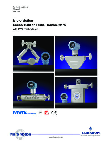
Model 1700 and 2700 physical specifications continuedDimensions ininches(mm)6 7/8(174)4-wire remote mountSeries 1000/2000transmitter2 7/16(62)3 15/16(99)3x 1/2-14 NPTor M20 x 1.5ø4 7/8(124)2 11/16(69)1(26)4 13/16(122)1 7/8(48)2 1/4(58)4 1/2(114)1 3/4(45)4 5/16(110)2 3/8(60)(to 1/2 NPTor M20)8 7/16(214)wall mount4 3/4(120)9 5/8(244)to centerline of 2” pipepipe mount6 7/8(174)3 15/16(99)2 11/16(69)3x 1/2-14 NPTor M20 x 1.58 3/16(207)4 3/8(111)9-wire remote Series1000/2000 transmitter7/8(22)2 9/16(65)2 13/16(71)3 11/16(93)13/16(21)4x ø3/8(10)3 1/16(78)2 13/16(71)4 5/16(110)8 7/16(214)wall mount9 5/8(244)to centerline of 2” pipepipe mountFor dimensions of integrally mounted transmitter and sensor, refer to sensor specifications.Series 1000 and 2000 Transmitters13
Model 1700 and 2700 physical specifications continuedDimensions ininches(mm)4 5/16(110)wall mount4(102)pole mount9-wire remotely mountedcore processor2 1/8(54)ø3 5/8(92)2X 2 1/4(58)2X 1/2”–14 NPTorM20 X 1.54 1/16(104)7/8(22)4X ø3/8(10)2 13/16(71)2 13/16(71)4 1/2(114)14Series 1000 and 2000 Transmitters3 1/4(83)7/8(22)2 9/16(65)4 1/2(114)
Series 1000 model number CodeMUCAZFCodeADEFGHIJMNOPSWCodeZZProduct DescriptionMicro Motion Coriolis MVD single variable flow transmitterMounting4-wire remote mount transmitterIntegral mount transmitter4-wire remote mount transmitter with 9-wire remote core processor9-wire remote transmitter (requires J-box sensor)Power18 to 30 VDC and 85 to 265 VAC; self switchingDisplayDual line display for process variables and totalizer reset (standard)No displayOutputOne mA; one frequency; RS485Intrinsically safe outputs: one mA, one frequencyConduit Connections1/2-inch NPT — no gland1/2-inch NPT with brass nickel cable gland1/2-inch NPT with stainless steel cable glandM20 — no glandM20 with brass nickel cable glandM20 with stainless steel cable glandApprovalsMicro Motion Standard (no approval)ULCSA (Canada only)CSA (US and Canada)ATEX — Equipment Category II 2 G (Zone 1, gas — increased safety)ATEX — Equipment Category II 2 G (Zone 1, gas — nish/SpanishSwedish/EnglishSoftware OptionsReserved for future useCodeFactory OptionsZStandard productXCEQ hardwareTypical Model Number:1700 I 1 1 A D M E ZZ ZSeries 1000 and 2000 Transmitters15
Series 2000 model number matrixModelProduct Description2700Micro Motion Coriolis MVD multivariable flow and density transmitterCodeMountingR4-wire remote mount transmitterIIntegral mount transmitterB4-wire remote mount transmitter with 9-wire remote core processorC9-wire remote transmitter (requires J-box sensor)CodePower118 to 30 VDC and 85 to 265 VAC; self switchingCodeDisplay1Dual line display for process variables and totalizer reset (standard)3No displayCodeOutputAOne mA; one frequency; RS485BOne mA; two configurable IO channels — default configurationCOne mA; two configurable IO channels — custom configurationDIntrinsically safe outputs: two mA, one frequencyEFOUNDATION fieldbus H1GPROFIBUS-PACodeConduit ConnectionsB1/2-inch NPT — no glandC1/2-inch NPT with brass nickel cable glandD1/2-inch NPT with stainless steel cable glandEM20 — no glandFM20 with brass nickel cable glandGM20 with stainless steel cable glandCodeApprovalsMMicro Motion Standard (no approval)UULCCSA (Canada only)ACSA (US and Canada)ZATEX — Equipment Category 2 (Zone 1 — increased safety)FATEX — Equipment Category 2 (Zone 1 — flameproof)CodeLanguage (quick reference installation guide/instruction anish/SpanishWSwedish/EnglishCodeSoftware Options 1ZFlow & density variables (standard)APetroleum measurement softwareXCEQ software option 1CodeSoftware Options 2ZNo software options 2Weights and measures custody transferW(1)AStandard fieldbus function blocksXCEQ software option 2CodeFactory OptionsZStandard productXCEQ hardwareTypical Model Number:2700 I 1 1 A D M E Z Z Z(1)Available with output option codes B and C only.16Series 1000 and 2000 Transmitters
Series 1000 and 2000 Transmitters17
Due to Micro Motion’s commitment to continuous improvement of our products, all specifications are subject to change without notice. MicroMotion is a registered trademark and MVD and EXPERT2 are trademarks of Micro Motion, Inc., Boulder, Colorado. PlantWeb is a registeredtrademark of Fisher-Rosemount, Clayton, Missouri. HART is a registered trademark of the HART Communication Foundation, Austin, Texas.FOUNDATION is a trademark of the Fieldbus Foundation, Austin, Texas.For the latest Micro Motion product specifications, view thePRODUCTS section of our Web site at www.micromotion.comMicro Motion Inc. USAWorldwide Headquarters7070 Winchester CircleBoulder, Colorado 80301Tel (303) 530-8400(800) 522-6277Fax (303) 530-8459Micro Motion AsiaEmerson Process Management1 Pandan CrescentSingapore 128461Republic of SingaporeTel (65) 777-8211Fax (65) 770-8003Micro Motion EuropeEmerson Process ManagementWiltonstraat 303905 KW VeenendaalThe NetherlandsTel 31 (0) 318 549 549Fax 31 (0) 318 549 559Micro Motion JapanEmerson Process ManagementShinagawa NF Bldg. 5F1-2-5, Higashi ShinagawaShinagawa-kuTokyo 140-0002 JapanTel (81) 3 5769-6803Fax (81) 3 5769-6843 2002, Micro Motion, Inc. All rights reserved.PS-00400 (6/02)
Micro Motion Series 1000 and 2000 Transmitters with MVD Technology! Product Data Sheet PS-00400 June 2002 www.micromotion.com. . Model 2700 transmitter. The frequency output can be configured as a discrete output, using batch targets entered from a host control system or from