Transcription
MultiFlex ETH1000 SeriesEthernet Motion Controller - User’s ManualRevision 1.2Precision MicroControl Corporation2075-N Corte del NogalCarlsbad, CA 92009 * USATel: 1-760-930-0101Fax: 1-760-930-0222www.pmccorp.comInformation: info@pmccorp.comTechnical Support: support@pmccorp.com
LIMITED WARRANTYAll products manufactured by PRECISION MICROCONTROL CORPORATION are guaranteed to be freefrom defects in material and workmanship, for a period of 2 years from the date of shipment. Liability islimited to FOB Factory repair, or replacement, of the product. Other products supplied as part of thesystem carry the warranty of the manufacturer.PRECISION MICROCONTROL CORPORATION does not assume any liability for improper use orinstallation or consequential damage. Copyright Precision Micro Control Corporation, 2008-2012. All rights reserved.Information in this document is subject to change without notice.Intel is a registered trademark of Intel Corporation.Microsoft and Windows are registered trademarks of Microsoft Corporation.Acrobat and Acrobat Reader are registered trademarks of Adobe Corporation.Precision MicroControl Corp.2075-N Corte del NogalCarlsbad, CA 92011 USATel:Fax:Web:Email: 1-760-930-0101 rt@pmccorp.comsales@pmccorp.comPrecision MicroControl Corp.
Table of ContentsPrologue. 3Introduction . 5Motion Control Primer . 11Axis I/O . 15The Command Set - the heart of the motion controller . 16Executing Operations with MCCL . 17Closed loop, open loop, and position verification. 20Why does a servo need to be tuned?. 22Position Feedback - Quadrature Incremental Encoder . 24Servo Amplifiers: Current Mode versus Velocity Mode. 25Stepper Motors - Full Step versus Micro Step . 26Homing - Why, When, and How . 27Software, Programming and Utilities . 29Controller Interface Types . 30Building Application Programs using Motion Control API . 31MCSpy - application program diagnostic tool. 36PMC Sample Programs. 37Motion Control API On-line Help . 38Motion Integrator . 40PMC Utilities . 43Connecting to the Controller . 47 /- 10V Analog Servo Command Connections . 48PWM (Pulse Width Modulation) Command Connections. 49Pulse Command Connections. 51Amplifier / Driver Enable Connections - Low Active. 52Driver Disable Connections - Low Active . 53Amplifier / Driver Enable Connections - High Active . 54Amplifier / Driver Fault Connections. 55Differential Incremental Encoder Connections . 56Single Ended Incremental Encoder Connections. 57Over-Travel Limit Connections. 58Home Sensor Connections . 60TTL Digital Input Connections . 61TTL Digital Output Connections . 62A/D Input Connections wiring example . 63Motion Control. 65Servo (analog command) Axis Setup. 65Tuning the Servo . 68Moving Servo Axes with Motor Mover. 77Stepper (pulse command) Axis Setup. 78Moving Stepper Axes with Motor Mover. 85Contour Motion (arcs and lines) . 91Electronic Gearing . 100Jogging . 101MultiFlex ETH 1000 Series User's Manuali
Table of ContentsDefining Motion Limits . 102Homing Axes . 105Motion Complete Indicators. 117On the Fly changes . 119Feed Forward (Velocity, Acceleration, Deceleration). 120Save and Restore Axis Configuration Settings . 122Application Solutions . 123Backlash Compensation. 123Emergency Stop . 125Encoder Rollover . 127Flash Memory Firmware Update . 128Saving and Restoring Axis Configuration Settings. 129Learning/Teaching Points. 133Building MCCL Macro Sequences . 135MCCL Multi-Tasking . 137Position Capture . 140Position Compare . 141Position Verification of an Open Loop Pulse Axis . 143PWM Servo Command. 147Record Motion Data. 150Resetting the Controller. 151Single Stepping MCCL Programs . 152Torque Mode Output Control. 154Turning off Integral gain during a move. 156Defining User Units. 159Watchdog Circuit . 163General Purpose I/O. 165Digital I/O . 165Configuring and Exercising the Digital I/O. 167Using the Digital I/O. 168A/D Inputs. 170Specifications. 173Motion Control Board. 173Analog Command Axis Specifications. 174Pulse Command Axis Specifications. 175I/O Signal Descriptions & Schematics . 177Signal Descriptions. 178Motor Command Signals . 178Encoder Feedback Signals. 179Default Axis Inputs. 179Default Axis Outputs. 181Default Configuration of General Purpose I/O . 183Circuit Schematics. 185Troubleshooting. 189Controller Error Codes . 199Motion Control API Error Codes. 200MCCL Error Codes . 201Glossary . 203Appendix . 207Default Axis Configuration Settings. 207Index . 209iiPrecision MicroControl Corp.
PrologueThis document provides configuration, programming and application information for the MultiFlex ETH1000 Series Ethernet motion controllers. Documentation for this product line includes the followingdocuments:MultiFlex ETH 1000 Series Quick Start GuideMultiFlex ETH 1000 Series Installation ManualMultiFlex ETH 1000 Series User’s Manual (this document)Motion Control API (Application Programming Interface) Reference ManualMotion Control Command Language (MCCL) Reference ManualThe latest versions of these documents can be downloaded from the Support section of PMC’s web siteat: www.pmccorp.com/support/mfxeth1000.php.Motion Controller InstallationiThis user manual provides detailed information about how to configure andprogram the controller. To learn how to install and initiate communication withthe controller, please see the MultiFlex ETH 1000 Series Installation Manual,This user manual applies to all MultiFlex ETH 1000 Series models, which include the following:Table 1. MultiFlex ETH 1000 Series ModelsModelMultiFlex ETH 1040MultiFlex ETH 1400MultiFlex ETH 1440MultiFlex ETH 1800MultiFlex ETH 1802MultiFlex ETH 1840TotalAxesAnalogand/orPWM AxesAC SineCommutationAxesStep/Dir orCW/CCWPulse AxesEncoderChannelsAnalogInputs(standard 488*822444440/444/88884488812888888* PWM onllyMultiFlex ETH 1000 Series User's Manual3
Page intentionallyleft blank4Precision MicroControl Corp.
Chapter1IntroductionThe MultiFlex ETH 1000 Series are programmable Ethernet-based motion controllers designed for highperformance multi-axis control of servo and stepper motors and I/O. Features and benefits offered bymodels in this series include: Fast communication via 10/100 Ethernet or independent (stand-alone) operation64-bit floating-point RISC CPU for high precision and dynamic rangeCustomizable FPGA-based I/O architectureUp to 12 total axes (model ETH-1840)4 to 8 axes analog servo control (models ETH-1400, -1440, -1800, -1840)8 axes PWM servo control (models ETH-1800, -1802, -1840)Up to 4 axes Step/Dir/CW/CCW pulse control (models ETH-1040, -1440, -1840)2 to 4 axes AC sine commutation (models -1400, -1440, -1800, -1840)Coordinated motion - interpolation, contouring, spline, master/slave, gearingTrapezoidal, S-curve and parabolic velocity profilesUser selectable 1, 2, 4 kHz servo update rate each axis16-bit analog servo command outputs20 MHz encoder inputs for high-speed, high-resolution moves5 MHz step/direction/CW/CCW outputs for high-speed microsteppingOn-the-fly changes in trajectory, direction and PID valuesOn-board multi-tasking frees host PC for other tasksEight general-purpose 14-bit A/D input channels (optional)Up to 76 user-assignable digital I/O channelsEncoder-failure detection circuitry for improved machine safetySub-microsecond position capture & compare I/O for rapid event triggering & synchronizationPlug-on interconnection boards can reduce or eliminate extra wires and cablesProgrammable in C/C /C#/.NET, Delphi, LabVIEW, VB and easy-to-use command languageDrivers and example programs with source code for Windows and LinuxProgramming API and commands are compatible across all PMC motion controllersGraphical setup, tuning, diagnostic and example programsCustom features and performance enhancements available upon requestMultiFlex ETH 1000 Series User's Manual5
IntroductionProcessorMultiFlex ETH 1000 series motion controllers feature an advanced 64-bit MIPS CPU core coupled withEthernet interface logic and internal cache memory to provide a powerful processing engine for highperformance motion control. An embedded multi-tasking real time kernel executes all motion controloperations with 64 bit floating point precision. 32 MB of DRAM and 8 MB of non-volatile FLASH memoryprovide on-board memory space for executing both the intrinsic motion control code as well as userprograms. A high-capacity FPGA interfaces directly with I/O such as encoders, analog inputs, controlsignals and general-purpose I/O and provides a great amount of flexibility for tailoring the controller tospecific application and performance requirements.PC computer minimum requirementsA MultiFlex ETH 1000 series controller can communicate with almost any Windows or Linux basedcomputer equipped with a 10/100 Ethernet adapter with PMC’s Motion Control API installed. At run-time,the controller can be connected to a host PC application or it can be configured to run stand-alone withouta host PC. In both cases, the controller’s CPU executes motion functions independently of the host PC,so other than the minimum requirements for the selected operating environment (Windows, Linux), thecontroller does not require the use of any additional PC resources.ProgrammingWindows and Linux programmers can create flexible and powerful control programs for PMC motioncontrollers in two ways:1. Writing a high-level program (C/C /C#/VB/Pascal/LabVIEW) that uses the functions supplied aspart of PMC’s Motion Control API (Application Programming Interface)and/or2. Using PMC’s embedded multi-tasking Motion Control Command Language (MCCL)Programmers can use either, or both, programming methods to command and control the motioncontroller. For example, a multi-threaded C/C /C# host application program can control and coordinatethe execution of motion and I/O, while one or more embedded MCCL routines can run simultaneously asbackground tasks on the controller board.To operate the controller in true stand-alone mode (without a host PC), MCCL macro routines must beused exclusively. In this case, one or more MCCL macro routines would be saved to the controller’s nonvolatile memory and one command macro would be configured to execute automatically on boot-up. Onthe other hand, if the controller remains connected to the host PC, then users can deploy anycombination of Motion Control API and MCCL programming that meets their needs.PMC’s WinControl terminal emulator utility (a Motion Control API component) provides a low-levelcommand interface used to send MCCL commands and routines to the controller for immediateexecution, or to download and save MCCL routines (also called “macros”) to the controller for laterexecution. Any MCCL command or routine can also be downloaded and called from a high-level program(C/C /C#/VB etc) via the appropriate Motion Control API function libraries.For additional information on Motion Control API and MCCL programming, please refer to the MotionControl API Reference Manual and the Motion Control Command Language (MCCL) ReferenceManual which are both available for download at: www.pmccorp.com/support/mfxeth1000.php.Motion Control API example6Precision MicroControl Corp.
IntroductionFunction prototypesC/C MCMoveAbsolute(HCTRLR hCtlr, WORD axis, double position);C#/.NETMcapi.Error Mcapi.MoveAbsolute(Int16 axis, Double position);Delphi:procedure MCMoveAbsolute( hCtlr: HCTRLR; axis: Word; position: Double ); stdcall;Sub MCMoveAbsolute(ByVal hCtrlr As Integer, ByVal axis As Integer, ByVal position As Double)VB:LabVIEW://C/C Example, Move Axis 1 to position 85000MCMoveAbsolute( hCtlr, 1, 85000.0 );MCCL command exampleMAMove AbsoluteMCCL commandapplies to:see also::aMAn a Axis number n integer or realAnalog Command Axis, Pulse Command AxisMR, PMThese MCCL command sequences cause the motion controller to execute a move to absolute position n.;Example:1MA10002MA-25000;Axis 1 move to position 1000;Axis 2 move to position -25000The following example illustrates MCCL multi-tasking. This example shows how a user would monitor thestate of a digital input while an axis is moving in order to ‘automatically’ stop the axis as soon as the inputis 1,NO,1JR-3MD101,1ST,1WS.05AL1,AR10,ET@100i;define user register 10 as input #4 active;define user register #100 as background task;jump to macro 101 when digital input #4 turns on; macro 101 defined, stop axis #1.;terminate background taskThere is not necessarily a one-to-one relationship between each Motion ControlAPI function and eacn MCCL command. Although any MCCL command can becalled directly using the Motion Control API’s pmccmdex() function, most MotionControl API functions ease the task of programming by encapsulating additionalfunctionality within each function.MultiFlex ETH 1000 Series User's Manual7
IntroductionProgramming ToolsPMC’s Motion Control API provides experienced programmers with a comprehensive function library.Develop application programs with VisualC/C /.NETComprehensive on-line help provides detailedfunction descriptions and program samplesSample programs with full source code aresupplied with the MCAPI. These C , VisualBasic, and Delphi sample programs allow theuser to; move an axis (servo or stepper),monitor position (actual, target, and optimal),monitor axis status & I/O (Limits /-, Home,Index, an Amplifier Enable), define or changemove parameters (Maximum velocity,acceleration/deceleration), Define or changethe servo PID parameters8Precision MicroControl Corp.
IntroductionSoftware Tools & UtilitiesPMC’s Motor Mover allows users to: move any orall motors, change velocities on the fly, definecycling routines, monitor position and statusPMC’s Motion Integrator's Setup Wizardswalk the user through the integrationprocess with external components (motors,encoders, sensors)The Servo Tuning Utility includes on-line help assistingwith both using the program and explaining thefundamentals of servo tuning. A complete Servo Tuningtutorial is also available on the Motion CDMultiFlex ETH 1000 Series User's Manual9
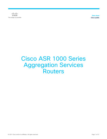
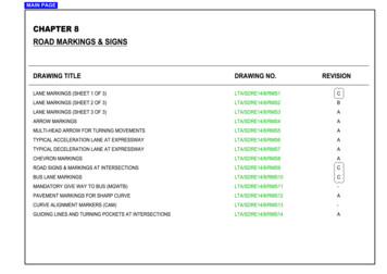
IntroductionI/O Configuration PanelPMC's I/O Configuration Panel (accessible from Windows Control Panel) allows users to re-configurethe channel numbers and logical functions of the digital I/O. The flexibility provided by this unique featureallows more efficient use of I/O resources and eases the task of connecting the controller to externaldevices.Figure 1. Digital I/O Configuration Panel10Precision MicroControl Corp.
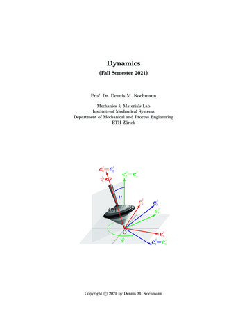
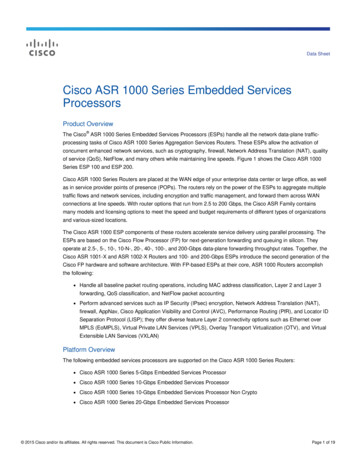
Chapter2Motion Control PrimerMotion Control ArchitectureA typical PC-based multi-axis motion control system is comprised of : A programmable motion controllerA user interface from which to program, command and monitor the motion controllerTwo or more servo or stepper motorsAn amplifier/driver for each motorA position feedback device for servo motors or closed-loop stepper motorsEnd of travel sensors (or limit switches) for axes with linear travelA mechanical stage and load. In this illustration, a stage is mounted on bearings and a lead screwis coupled to the motor shaft. When the motor shaft rotates, the stage moves along the leadscrew.Ethernet cableMulti-AxisMotionControllerAxis 1Axis 2Axis 3Axis 4PC computerServo or Stepper MotorLead screwStageAmplifier/DriveEncoderNegative LimitsensorPositive LimitsensorFigure 2: Typical motion control systemMultiFlex ETH 1000 Series User's Manual11
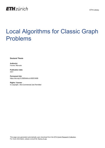
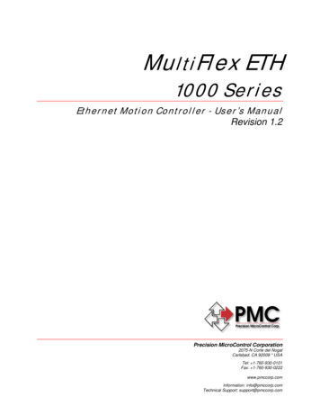
Motion Control PrimerMotion Controller Functional Block DiagramStepperDriverStepperMotorDigital outputsAnalog inputsDigital inputs 2V to 24VGeneral Purpose Digital I/O(PLC type PulseAxisAxis I/O(home, limits,amp enable.)DAC( /- 10V)Trajectory Generator(velocity profiles)Axis 1Axis 2Axis 3. etc.Command e DriverNon-VolatileUser-ProgramStorageRAM MemoryPID FilterAxis 1Axis 2Axis 3. etc.ServoAmplifierEncoderDecode 2V to 24VMotion ControllerHigh-speed encoder capture inputsServoMotorHigh-speed encoder compare outputsApplicationProgrammingInterfacePC Computer12QuadratureEncoderPrecision MicroControl Corp.
Motion Control PrimerMotion Controller TasksThe MutiFlex ETH 1000 Series motion controllers feature a 64-bit floating-point CPU, FPGA, I/O bufferingcircuitry, a real time kernel and proprietary motion control firmware which work in combination to controlthe position, velocity, or torque of as many as twelve axes. The primary operations performed by themotion controller are:Trajectory generation (Trapezoidal, S curve, and Parabolic)PID filter (servo loop)I/O and error handlingHost communicationOn a periodic basis (each 250 microseconds to 1 millisecond, depending on the performance modechosen by the user), the controller’s CPU receives an internal interrupt that automatically triggers theexecution of the controller’s trajectory generator. Based on user commanded motion, the trajectorygenerator then calculates a new desired positions and velocity values for all axes. /- 10 Volt Analog Servo ControlThe target positions calculated by the trajectory generator are passed to each respective PID filter forgeneration of a /- 10V analog servo command signal for each axis. In addition to the trajectorygenerator, every millisecond, the controller performs housekeeping and error checking (over travel limits& following error exceeded) tasks.PID FilterThe position feedback loop or PID (Proportional-Integral-Derivative) filter is executed every 1000 – 250microseconds (1 - 4 kHz), depending on the performance mode chosen by the user. Each PID filterexecution results in the writing of a value to the DAC (Digital to Analog Converter) which is proportionalto:Position error (the difference between the optimal (desired) position and the current position)Plus the integral of the errorPlus the derivative of the errorThe following discrete-time equation illustrates the control performed by the servo controller:u(n) Kp*E(n) Ki sum E(n) Kd[E(n') - E(n' - 1)]where u(n) is the analog command output level at sample time n, E(n) is the position error at sample timen, n' indicates sampling at the derivative sampling rate, and kp, ki, and kd are the discrete-time filterparameters loaded by the users. The first term, the proportional term, provides a restoring forceproportional to the position error. The second term, the integration term, provides a restoring force thatgrows with time. The third term, the derivative term, provides a force proportional to the rate of change ofposition error. It provides damping in the feedback loop. The sampling interval associated with thederivative term is user-selectable; this capability enables the servo controller to control a wider range ofinertial loads.MultiFlex ETH 1000 Series User's Manual13
Motion Control PrimerPosition Feedback via Incremental EncoderThe motion controller monitors the position of a servo via an incremental encoder. Both differential (A , A, B , B-, Z , Z-) and single ended (A, B, Z) incremental encoders are supported. The maximum encoderfrequency is 20 MHz (@ 50% duty cycle). The two quadrature signals from the encoder are used to keeptrack of the position of the motor. Each time a logic trans
MultiFlex ETH 1000 Series User's Manual 5 Introduction The MultiFlex ETH 1000 Series are programmable Ethernet-based motion controllers designed for high- performance multi-axis control of servo and stepper motors and I/O. Features and benefits offered by