Transcription
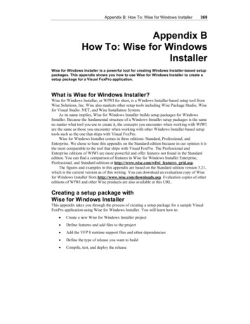
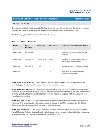
18-AC71D1-5Installer’s GuideCondensing Units4TTR3ALL phases of this installation must comply with NATIONAL, STATE AND LOCAL CODESIMPORTANT — This Document is customer property and is to remain with this unit. Please return to serviceinformation pack upon completion of work.These instructions do not cover all variations insystems nor provide for every possible contingencyto be met in connection with installation. All phasesof this installation must comply with NATIONAL,STATE AND LOCAL CODES. Should further informationbe desired or should particular problems arise which arenot covered sufficiently for the purchaser’s purposes, thematter should be referred to your installing dealer or local distributor.A. General!!UNIT CONTAINS R-410A REFRIGERANT!R-410A OPERATING PRESSURE EXCEEDS THELIMIT OF R-22. PROPER SERVICE EQUIPMENT ISREQUIRED. FAILURE TO USE PROPER SERVICETOOLS MAY RESULT IN EQUIPMENT DAMAGE ORPERSONAL INJURY.SERVICEWARNINGThis information is intended for use by individuals pos ses s ing adequate backgrounds of electrical and mechanical experience. Any attempt to repair a central air condition ingproduct may result in personal injury and or p roperty damage.The manufacturer or seller cannot be respon sible for theinterpretation of this information, nor can it a ssume any liabilityin connection with its use.CAUTIONUSE ONLY R-410A REFRIGERANT ANDAPPROVED POE COMPRESSOR OIL.15 FT. ABOVE UNIT — UNRESTRICTEDNOTICE:Trane has always recommended installing Traneapproved matched indoor and outdoor systems.The benefits of installing approved matched systemsare maximum efficiency, optimum performance andbest overall system reliability.!WARNINGThese units use R-410A refrigerant which operates at 50 to 70%higher pressures than R-22. Use only R-410A approved serviceequipment. Refrigerant cylinders are painted a “Rose” color toindicate the type of refrigerant and may contain a “dip” tubeto allow for charging of liquid refrigerant into the system. AllR-410A systems use a POE oil that readily absorbs moisture fromthe atmosphere. To limit this “hygroscopic” action, the systemshould remain sealed whenever possible. If a system has beenopen to the atmosphere for more than 4 hours, the compressoroil must be replaced. Never break a vacuum with air and alwayschange the driers when opening the system for componentreplacement. For specific handling concerns with R-410A andPOE oil, reference Retrofit BulletinSSC-APG011-EN.Check for transportation damage after unit is uncrated.Report promptly, to the carrier, any damage found to theunit.To determine the electrical power requirements of the unit,refer to the nameplate of the unit. The electrical poweravailable must agree with that listed on the nameplate.B. Location and Preparationof the Unit1. When removing unit from the pallet, notice the tabs onthe basepan. Remove tabs by cutting with a sharp toolas shown in Figure 2 (see page 2).2. The unit should be set on a level support pad at leastas large as the unit base pan, such as a concreteslab. If this is not the application used please refer toapplication bulletin SSC-APG002-EN.3. The support pad must NOT be in direct contact withany structure. Unit must be positioned a minimumof 12" from any wall or surrounding shrubbery toinsure adequate airflow. Clearance must be provided
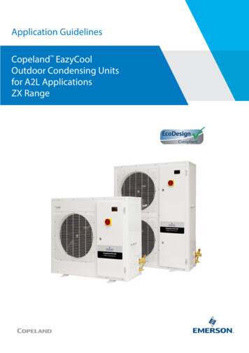
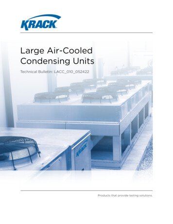
Installer’s Guide2BASEPAN TAB REMOVALin front of control box (access panels) & any other siderequiring service access to meet National ElectricalCode. Also, the unit location must be far enough awayfrom any structure to prevent excess roof run-off waterfrom pouring directly on the unit. Do not locate unit(s)close to bedroom(s).4. The top discharge area must be unrestricted for at leastfive (5) feet above the unit.5. When the outdoor unit is mounted on a roof, be sure theroof will support the unit’s weight. Properly selectedisolation is recommended to prevent sound or vibrationtransmission to the building structure.6. The maximum length of refrigerant lines from outdoorto indoor unit should NOT exceed sixty (60) feet.7. If outdoor unit is mounted above the air handler,maximum lift should not exceed sixty (60) feet (suctionline). If air handler is mounted above condensing unit,maximum lift should not exceed sixty (60) feet (liquidline).NOTE:Refer to “Refrigerant Piping Software” Pub. No. 32-3312-0*(the position of the * denotes the latest revision number).8. Locate and install indoor coil or air handler inaccordance with instruction included with that unit.C. Installing Refrigerant Lines! CAUTIONIf using existing refrigerant lines make certain that alljoints are brazed, not soldered.Condensing units have provisions for braze connections.Pressure taps are provided on the service valves of outdoorunit for compressor suction and liquid pressures.The indoor end of the recommended refrigerant line setsmay be straight or with a 90 degree bend, depending uponsituation requirements. This should be thoroughly checkedout before ordering refrigerant line sets.The gas line must always be insulated.!CAUTIONIn scroll compressor applications, dome temperaturesmay be hot. Do not touch top of compressor, may causeminor to severe burning.The units are factory charged with the system chargerequired when using fifteen (15) feet of rated connectingline. Unit nameplate charge is with twenty-five (25) feet ofline set.Final refrigerant charge adjustment is necessary.Use the Subcooling Charging procedure on page 6 or in theoutdoor unit Service Facts.1. Determine the most practical way to run the lines. 2009 Trane2. Consider types of bends to be made and space limitations.NOTE:Large diameter tubing will be very difficult to rebend onceit has been shaped.3. Determine the best starting point for routing therefrigerant tubing — INSIDE OR OUTSIDE THESTRUCTURE.4. Provide a pull-thru hole of sufficient size to allow bothliquid and gas lines.5. Be sure the tubing is of sufficient length.6. Uncoil the tubing — do not kink or dent.7. Route the tubing making all required bends and properly secure the tubing before making connections.8. To prevent a noise within the building structure due tovibration transmission from the refrigerant lines, thefollowing precautions should be taken:a. When the refrigerant lines have to be fastenedto floor joists or other framing in a structure, useisolation type hangers.b. Isolation hangers should also be used whenrefrigerant lines are run in stud spaces or enclosedceilings.c. Where the refrigerant lines run through a wall orsill, they should be insulated and isolated.d. Isolate the lines from all ductwork.D. Service Valve OperationBrass Liquid and Gas Line Service ValvesThe Brass Liquid and Gas Line Service Valves are factoryshipped in the seated position to hold factory charge. Thepressure tap service port (when depressed) opens only tothe field brazing side of the valve when the valve is in theseated position. The liquid line valve is not a back seatingvalve (see WARNING below).!WARNINGExtreme caution should be exercised when openingthe Liquid Line Service Valve. Turn valve stemcounterclockwise only until the stem contacts the rollededge. (See Figure 3.) No torque is required.Brass Gas Line Ball Service ValveThe Brass Gas Line Ball Service Valve is shipped in theclosed position to hold the factory refrigerant charge. Thepressure tap service port (when depressed) opens onlyto the field brazing side when the valve is in the closedposition. The Gas Line Ball Service Valve is full open witha 1/4 turn. See Figure 4.Brazing Refrigerant Lines1. Remove lower access cover to access service valves.2. Before brazing, remove plugs from external copper stubtubes. Clean internal and external surfaces of stubtubes prior to brazing.3. Cut and fit tubing, minimizing the use of sharp90 bends.4. Insulate the entire gas line and its fittings.5. Do NOT allow uninsulated liquid line to come in directcontact with bare gas line.6. Precautions should be taken to avoid heatdamage to the pressure tap valve core duringbrazing. It is recommended that the pressuretap port valve core be removed and a wet ragwrapped around the valve body.18-AC71D1-5
Installer’s Guide3LIQUID LINE SERVICE VALVE6. If vacuum gauge does not rise above 500 microns in one(1) minute, the evacuation should be complete.7. Blank off vacuum pump and micron gauge, close valveson manifold gauge set.NOTE:DO NOT VENT REFRIGERANT INTO THE ATMOSPHERE.NOTE:A 3/16" Allen wrench is required to open liquid lineservice valve. A 1/4" Open End or Adjustable wrench isrequired to open gas line valve. A 3/4" Open End wrenchis required to take off the valve stem cap.NOTE:Use care to make sure that no moisture enters pressuretap port, while wet rag is being used.NOTE:Precautions should be taken to avoid heat damage tobasepan during brazing. It is recommended to keep theflame directly off of the basepan.7. Use a Dry Nitrogen Purge and Brazing Alloy withoutflux when brazing the field line to the copper factoryconnection. Flow dry nitrogen into either valvepressure tap port, thru the tubing and out the otherport while brazing.8. Braze using accepted good brazing techniques.Leak CheckIMPORTANT:Replace pressure tap port valve core before attaching hosesfor evacuation.After the brazing operation of refrigerant lines to both theoutdoor and indoor units is completed, the field brazedconnections must be checked for leaks. Pressurize throughthe service valve ports, the indoor unit and field refrigerantlines with dry nitrogen to 350-400 psi. Use soap bubbles orother leak-checking methods to see that all field joints areleak-free! If not, release pressure; then repair!8. The liquid line shut-off valve can now be opened.Remove shut-off valve cap. Fully insert hex wrenchinto the stem and backout counterclockwise until valvestem just touches rolled edge (approximately five [5]turns) observing WARNING statement on page 2. See Figure 3.9. Replace liquid service pressure tap port cap and valvestem cap. These caps MUST BE REPLACED toprevent leaks. Replace valve stem cap and pressure tapcap finger tight, then tighten an additional 1/6 turn.10. The gas valve can now be opened. Open the gas valveby removing the shut-off valve cap and turning thevalve stem 1/4 turn counterclockwise, using 1/4" OpenEnd or Adjustable wrench. See Figures 4 and 5.11. The gas valve is now open for refrigerant flow. Replacevalve stem cap to prevent leaks. Again, these capsMUST BE REPLACED to prevent leaks. Replacevalve stem cap and pressure tap cap finger tight, thentighten an additional 1/6 turn. See Figures 4 and 5.If refrigerant lines are longer than fifteen (15) feetand/or a different size than recommended, it will benecessary to adjust system refrigerant charge uponcompletion of installation. See page 6 or the unitService Facts.4GAS LINE BALL SERVICE VALVECAP1/4 TURN ONLYCOUNTERCLOCKWISEFOR FULL OPENPOSITIONSystem EvacuationNOTE:Since the outdoor unit has a refrigerant charge, the gasand liquid line valves must remain closed.VALVE STEMUNIT SIDEOF VALVE1. Upon completion of leak check, evacuate the refrigerantlines and indoor coil before opening the gas and liquidline valves.PRESSURE TAP PORT2. Attach appropriate hoses from manifold gauge to gasand liquid line pressure taps.NOTE:Unnecessary switching of hoses can be avoided andcomplete evacuation of all lines leading to sealed systemcan be accomplished with manifold center hose andconnecting branch hose to a cylinder of R-410A andvacuum pump.GAS LINE CONNECTION5GAS LINE SERVICE VALVE3. Attach center hose of manifold gauges to vacuumpump.4. Evacuate until the micron gauge reads no higher than350 microns.5. Close off valve to vacuum pump and observe the microngauge. If gauge pressure rises above 500 microns in one (1)minute, then evacuation is incomplete or system has a leak.18-AC71D1-53
Installer’s GuideE. Electrical Connections! WARNINGF. Compressor Start-UpAfter all electrical wiring is complete, SET THETHERMOSTAT SYSTEM SWITCH IN THE OFFPOSITION SO COMPRESSOR WILL NOT RUN, and applypower by closing the system main disconnect switch. Thiswill activate the compressor sump heat (where used). Donot change the Thermostat System Switch until power hasbeen applied for one (1) hour. Following this procedure willprevent potential compressor overload trip at the initialstart-up.When installing or servicing this equipment, ALWAYSexercise basic safety precautions to avoid the possibilityof electric shock.1. Power wiring and grounding of equipment must complywith local codes.2. Power supply must agree with equipment nameplate.3. Install a separate disconnect switch at the outdoor unit.G. Operational andCheckout Procedures4. Ground the outdoor unit per local code requirements.Final phases of this installation are the unit Operationaland Checkout Procedures which are found in thisinstruction (see table below and pages 6 and 8). To obtainproper performance, all units must be operated and chargeadjustments made in accordance with procedures found onpage 6 and in the Service Facts.5. Provide flexible electrical conduit whenever vibrationtransmission may create a noise problem within thestructure.6. The use of color coded low voltage wire is recommendedto simplify connections between the outdoor unit, thethermostat and the indoor unit.IMPORTANT:Perform a final unit inspection to be sure that factory tubinghas not shifted during shipment. Adjust tubing if necessary sotubes do not rub against each other when the unit runs. Alsobe sure that wiring connections are tight and wire routing issecure.Table 1 — NEC Class II Control Wiring24 VOLTSWIRE SIZEMAX. WIRE LENGTH18 AWG150 FT16 AWG225 FT.14 AWG300 FT.H. Seacoast ShieldIf installed within one mile of salt water, includingseacoasts and inland waterways, models without factorysupplied Seacoast Salt Shields require the addition ofBAYSEAC001 (Seacoast Kit) at installation time. Pleaserefer to Application Guide SS-APB006-EN: Trane - SeacoastApplications and Seacoast Corrosion Protection BulletinUN-SVB11A-EN.7. Table 1 defines maximum total length of low voltagewiring from outdoor unit, to indoor unit, and to thermostat.8. Mount the indoor thermostat in accordance withinstruction included with the thermostat. Wire perappropriate hook-up diagram (included in theseinstructions).IMPORTANT:See Limited Warranty information in Use and Care Manual.I. TroubleshootingTROUBLESHOOTING CHART — WHAT TO CHECKCHWITDSPEE TIONSNSCTRI. FAO.D IT RES RFLOWCU. AI AT. CIRD I.DHEREF RICTE UPER NTSOPERESKCSTUIONTXV CULATWIRREC IRFLO. AIR O.D. A LESO.DDABCTE DENS ADTRINRES ONCO AP. LONEEVIVE CHARGESSREXC T OVE ARGEHNERA NDERC SORRIGSUREF RANT MPRE ROOERIG ENT C RESSIPREFOMFFICUSEINE TUCK C AGE FTILSVOL R COLOW TACTO ERMCON SFORANINGL TR E WIRTROAG ACTSCON VOLTTCON LAYLOWTORRETAC TART ORSTCONACICAP ITORRTSTA CAPAC LIORUNPR.COM INGWIRAGELYOLT SUPPHVERPOWHIGSYSTEM FAULTSREFRIGERANT CIRCUITPLiquid Pressure Too HighLiquid Pressure Too LowSSuction Pressure Too HighSPSPPPPSSSSPSSuction Pressure Too LowSSLiquid Refrig. Floodback TXV SystemCompressor Runs Inadequate or No CoolingSPSPPSSSSSPSPSPSSPI.D. Coil FrostingSELECTRICALCompressor & O.D. Fan Do Not StartPPCompressor Will Not Start But O.D. Fan RunsPO.D. Fan Won’t StartPCompressor Hums But Won’t StartPCompressor Cycles on IOLPPI.D. Blower Won’t StartP - Primary CausesSSPPPPSPPPPPSPPPSPSSSPSPSSSSSPS - Secondary Causes418-AC71D1-5
Installer’s GuideTypical Field Hook-up DiagramsPRINTED FROM B152901 P02NOTE*PRINTED FROM B152903 P02present only on 2 stage*W2thermostatand furnaceNotes:1. Be sure power supply agrees with equipment nameplate.2. Power wiring and grounding of equipment must comply with local codes.3. Low voltage wiring to be No. 18 AWG minimum conductor.4. ODT-B must be set lower than ODT-A.5. If outdoor thermostats (ODT) are not used, connect W1 to W2 and W3.18-AC71D1-5LEGENDFACTORY WIRINGFIELD WIRING5
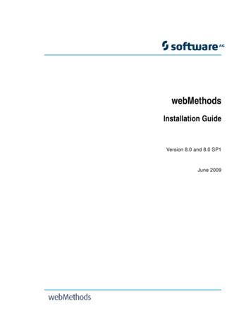
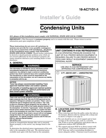
Installer’s GuideSubcooling Charging In Cooling Above 55 F OD Ambientmatch the table, or remove refrigerant to lower thepressure. Again, wait twenty (20) minutes for thesystem conditions to stabilize before adjusting chargeagain.The Trane company has always recommended installingTrane approved matched indoor and outdoor systems.All Trane split systems are ARI rated with only TXV indoorsystems.8. When system is correctly charged, you can refer toSystem Pressure Curves (in Service Facts) to verifytypical performance.The benefits of installing approved indoor and outdoor splitsystems are maximum efficiency, optimum performance andthe best overall system reliability.The following charging methods are thereforeprescribed for systems with indoor TXVs.1. Subcooling (in the cooling mode) is theonly recommended method of chargingabove 55 F ambient temperatures.2. For best results - the indoor temperatureshould be kept between 70 F to 80 F. Addsystem heat if needed.3. At start-up, or whenever charge isremoved or added, the system must beoperated for a minimum twenty (20)minutes to stabilize before accuratemeasurements can be made.4. Measure Liquid Line Temperature andRefrigerant Pressure at service valves.5. Determine total refrigerant line length,and height (lift) if indoor section is abovethe condenser.6. Determine the Design Subcool ChargingTemperature from the unit nameplate.7. Locate this value in the appropriatecolumn of the Subcooling Charging Table.Locate your liquid line t emperaturein the left column of the table, and the intersecting liquid line pressure underyour nameplate subcool value column.Add refrigerant to raise the pressure toLIQUIDTEMP( F)R-410A REFRIGERANT CHARGING CHARTDESIGN SUBCOOLING ( LIQUID GAGE PRESSURE 60386413441470501533Refer to Service Facts orInstaller's Guide for charging method.From Dwg. D154557P01 Rev. 2REFRIGERANTLINE LIFT (FEET)SUBCOOL CHARGING TABLE CORRECTIONS FOR LINE LENGTH AND RISE60504030Add 10 psig to Subcool Charging Table Pressure2520Use Design Subcool Value from Table15100 Subtract 10 psig from S.C. Table Pressure10202530406080TOTAL REFRIGERANT LINE LENGTH (FEET)618-AC71D1-5
Installer’s Guide4TTR3 Outline DrawingMODELSBASEFIG.ABCDEFGHJK4TTR3018A31832 (32-3/4)829 (32-5/8)756 (29-3/4)1/23/8143 (5-5/8)92 (3-5/8)210 (8-1/4)79 (3-1/8)508 (20)4TTR3024A31832 (32-3/4)829 (32-5/8)756 (29-3/4)5/83/8143 (5-5/8)92 (3-5/8)210 (8-1/4)79 (3-1/8)508 (20)4TTR3030A31832 (32-3/4)829 (32-5/8)756 (29-3/4)3/43/8143 (5-5/8)92 (3-5/8)210 (8-1/4)79 (3-1/8)508 (20)4TTR3036B31933 (36-3/4)829 (32-5/8756 (29-3/4)3/43/8143 (5-5/8)92 (3-5/8)210 (8-1/4)79 (3-1/8)508 (20)4TTR3042A41841 (33-1/8)946 (37-1/4)870 (34-1/4)3/43/8152 (6)98 (3-7/8)219 (8-5/8)86 (3-3/8)508 (20)4TTR3048A41841 (33-1/8)946 (37-1/4)870 (34-1/4)7/83/8152 (6)98 (3-7/8)219 (8-5/8)86 (3-3/8)508 (20)4TTR3060A411045 (41-1/8) 946 (37-1/4)870 (34-1/4)7/83/8152 (6)98 (3-7/8)219 (8-5/8)86 (3-3/8)508 (20)18-AC71D1-5From Dwg. D152898Note: All dimensions are in MM (Inches).7
Installer’s GuideMounting Hole LocationNote: All dimensions arein MM (Inches).NOTE:For model base size,see table on page 7.From Dwg. 21D152637 Rev. 1Checkout ProcedureAfter installation has been completed, it is recommended that the entire system be checked against the following list:1. Refrigerant Line, Leak checked. [ ]2. Suction Lines and Fittings properly insulated. []3. Have all Refrigerant Lines been secured andisolated properly?. [ ]4. Have passages through masonry been sealed?If mortar is used, prevent mortar from cominginto direct contact with copper tubing. []5. Verify tightness of all electrical connects. [ ]6. Observe outdoor fan during on cycle for clearanceand smooth operation. []7. Indoor coil drain line drains freely. Pour waterinto drain pan. []Tranewww.trane.com8. Supply registers and return grilles open andunobstructed. []9. Return air filter installed. []10. Thermostat thermometer is accurate. Checkagainst a reliable thermometer. Adjust perinstructions with thermostat. []11. Is correct speed tap being used?(Indoor blower motor). []12. Operate complete system in each mode toinsure safe operation. []04/09Trane has a policy of continuous product and product data improvement and it reserves the right to changedesign and specifications without notice.
Trane has always recommended installing Trane approved matched indoor and outdoor systems. The benefits of installing approved matched systems are maximum efficiency, optimum performance and best overall system reliability. ! WARNING These units use r 410A refrigerant which operates at 50 to 70% higher pressures than r 22.