Transcription
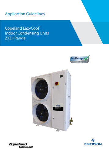
Application GuidelinesCopeland EazyCoolOutdoor Condensing Unitsfor A2L ApplicationsZX Range
About these guidelines . 11Safety instructions . 11.1 Icon explanation . 11.2 Safety statements . 11.3 General instructions . 22Product description . 32.1 General information about Copeland EazyCool ZX condensing units . 32.2 EU Ecodesign Directive 2009/125/EC . 32.3 Main product features and dimensions . 32.4 Product nameplate . 52.5 Nomenclature . 52.6 Application range . 62.6.1Qualified refrigerants and oils . 62.6.2Application limits . 62.7 BOM variations . 62.8 P&I diagrams . 72.8.1ZXMY units . 72.8.2ZXDY units . 82.9 Main components description . 92.9.1Compressor . 92.9.2Condenser fan(s) . 92.9.3Housing . 92.10 XCM25D Electronic controller – Features . 102.10.1 Description . 102.10.2 Functionalities . 102.10.3 Modbus communication . 112.10.4 Main control & safety features . 112.10.5 Additional features for customization . 122.11 XCM25D Electronic controller – Programming . 182.11.1 Programming the local display . 182.11.2 Remote display CCM60 . 192.11.3 Single commands . 192.11.4 Double commands – Entering programming level 1 "Pr1" . 202.11.5 How to program the parameters (Pr1 and Pr2) . 202.11.6 Entering programming level 2 "Pr2" . 202.11.7 Fast access menu . 212.12 Controller keyboard . 212.12.1 How to lock the keyboard . 212.12.2 How to unlock the keyboard . 212.13 Parameters level 1 – Required settings . 22AGL Unit ZX A2L E Rev00
2.14 Digital operation . 222.15 Pumpdown mode . 232.15.1 External pumpdown without XCM25D integration (not available with ZXDY units)232.15.2 Pumpdown by the unit controller (not available with ZXDY units) . 232.15.3 Pumpdown with room thermostat (not available with ZXDY units) . 242.15.4 Internal pumpdown with temperature sensor (case temperature) . 252.16 Reset to factory settings – Emerson "Hot Key" . 262.16.1 How to save factory settings or user settings . 262.16.2 Applicable hot key for ZX units with XCM25D controller . 262.16.3 Location of the "Hot Key" plug connection on the XCM25D controller . 262.16.4 How to program a "Hot Key" from the controller (upload) . 262.16.5 How to program a controller using an Emerson "Hot Key" (download) . 272.17 Troubleshooting – Alarm history . 272.18 Compressor motor protection . 282.19 System pressure protection . 282.20 Other inputs of the XCM25D controller . 282.20.1 Customer-supplied control (room thermostat). 282.20.2 Case temperature controller . 282.20.3 Ambient temperature sensor . 282.21 Alarm output (DO5) of the XCM25D controller . 283Installation . 293.1 Condensing unit handling . 293.1.1Transport and storage . 293.1.2Weights. 293.2 Refrigeration piping connections . 303.2.1Refrigeration piping installation . 303.2.2Brazing recommendations. 313.2.3Brazing procedure . 323.3 Electrical connection . 323.3.1Power supply connections. 333.3.2Maximum operating currents for cable selection . 333.3.3Electrical wiring . 333.3.4Electrical protection standard (protection class) . 333.3.5Terminal box . 333.3.6Low-pressure protection . 343.3.7Crankcase heater . 343.3.8Insulation material . 343.3.9Sound and vibration . 343.3.10 High-potential testing. 343.3.11 Circuit breaker with overcurrent protection . 353.4 Location & fixings . 35AGL Unit ZX A2L E Rev00
4Start-up & operation. 374.1 Strength-pressure test . 374.2 System tightness test . 374.3 Evacuation . 374.4 Charging procedure . 384.4.1Refrigerant charging procedure . 384.4.2Oil charging procedure . 394.4.3Oil separator . 394.5 Rotation direction of scroll compressors . 394.6 Maximum compressor cycle . 394.7 Checks before starting & during operation . 394.8 Pressure fluctuations in case of digital unit . 404.9 Pumpdown cycle . 405Maintenance & repair . 415.1 General considerations . 415.2 Qualification of workers . 415.3 Preparation and work procedure . 425.4 Disassembling system components . 425.5 Exchanging the refrigerant . 425.6 Replacing a compressor . 425.7 Replacing the crankcase heater . 435.8 Electrical terminations . 445.9 Condenser fins . 455.10 Routine leak testing . 455.11 Condenser fans & motors . 456Certification & approval . 457Dismantling & disposal . 45DISCLAIMER . 46Appendix 1: Overview of the ZX unit components . 47Appendix 2: Wiring diagram – ZXMY units (380-420 V / 3 Ph / 50 Hz) . 48Appendix 3: Wiring diagram – ZXDY units (380-420 V / 3 Ph / 50 Hz). 49Appendix 4: Parameters level 1 . 50Appendix 5: Alarm menu . 51Appendix 6: Additional features for customization . 56Appendix 7: Temperature / resistance curve for B7 Sensor (customer option) . 60Appendix 8: List of tables and figures . 61AGL Unit ZX A2L E Rev00
About these guidelinesThe purpose of these application guidelines is to provide guidance in the application of Copeland EazyCool ZX outdoor condensing units. They are intended to answer the questions raised whiledesigning, assembling and operating a system with these products.Besides the support they provide, the instructions listed herein are also critical for the proper andsafe functioning of the condensing units. The performance and reliability of the product may beimpacted if the product is not used according to these guidelines or is misused.These application guidelines cover stationary applications only. For mobile applications, contactApplication Engineering as other considerations may apply.1Safety instructionsCopeland EazyCool ZX outdoor condensing units are manufactured according to the latestEuropean safety standards. Particular emphasis has been placed on the user's safety.These condensing units are intended for installation in machines and systems in accordance withthe European Machinery Directive MD 2006/42/EC, the Pressure Equipment DirectivePED 2014/68/EU and the Low Voltage Directive LVD 2014/35/EU. They may be put to service onlyif they have been installed in systems according to instructions and conform to the correspondingprovisions of legislation.IMPORTANT: Only dedicated compressors and condensing units are allowed to be used withflammable refrigerants. Emerson marks all compressors and units that are qualified forflammable refrigerants with a sticker indicating the usage of such refrigerants. Systems usingflammable refrigerants must be executed correctly while observing safety rules, as specifiedin corresponding safety standards such as, but not limited to EN 378. They must comply withany and all applicable legislation and regulations. Ensuring compliance remains the user’sresponsibility.These instructions should be retained throughout the lifetime of both the compressor and thecondensing unit.You are strongly advised to follow these safety instructions.1.1Icon explanationWARNINGThis icon indicates instructions toavoid personal injury and materialdamage.Fire hazardThis icon indicates a risk of flammableatmosphere.High voltageThis icon indicates operations with adanger of electric shock.CAUTIONThis icon indicates instructions toavoid property damage and possiblepersonal injury.Danger of burning or frostbiteThis icon indicates operations with adanger of burning or frostbite.IMPORTANTThis icon indicates instructions toavoid malfunction of the compressor.Explosion hazardThis icon indicates operations with adanger of explosion.NOTEThiswordindicatesarecommendation for easier operation.Danger of explosive atmosphereThis icon indicates a risk of explosiveatmosphere.1.2Safety statements Condensing units must be employed only for their intended use. The system has to belabelled according to the applicable standards and legislation. Only qualified and authorized RACHP personnel are permitted to install, commission andmaintain this equipment. Only competent personnel (as specified in EN 13313) qualifiedfor flammable refrigerant handling is permitted to commission, initiate and maintain theAGL Unit ZX A2L E Rev001
compressor/refrigeration systems; non-trained personnel, including the user, are notallowed to do so and must call on an expert.The maximum refrigerant charge is specified in standards such as, but not limited toEN 378, EN 60335-2-40 and EN 60335-2-89. The system designer shall implement all safetymeasures defined by the applicable standards and the maximum refrigerant charge shallnot be exceeded.If a flammable atmosphere is detected, immediately take all necessary precautions tomitigate the risk as determined in the risk assessment.Electrical connections must be made by qualified electrical personnel.All valid safety standards for connecting electrical and refrigeration equipment must beobserved.The national legislation and regulations regarding personnel protection must be observed.Use personal safety equipment.Safety goggles, gloves,protective clothing, safety boots and hard hats should be worn wherenecessary.1.3General instructionsWARNINGPressurized system! Serious personal injuries and/or systembreakdown! Accidental system start before complete set-up must be avoided.Never leave the system unattended without locking it out electrically when it ison vacuum and has no refrigerant charge, when it has a holding charge ofnitrogen, or when the compressor service valves are closed.WARNINGSystem breakdown! Personal injuries! Never install a system in the fieldand leave it unattended when it has no charge, a holding charge, or with theservice valves closed without electrically locking out the system.System breakdown! Personal injuries! Only approved refrigerants andrefrigeration oils must be used.WARNINGHigh shell temperature! Burning! Do not touch the compressor until it hascooled down. Ensure that other materials in the area of the compressor do notcome into contact with it. Lock and mark accessible sections.CAUTIONOverheating! Bearing damage! Do not operate compressors withoutrefrigerant charge or without being connected to the system.CAUTIONContact with refrigerant oil! Material damage! Polyolester oil (POE) mustbe handled carefully and the proper protective equipment (gloves, eyeprotection, etc.) must be used at all times. POE must not come into contactwith any surface or material that it might damage, including without limitation,certain polymers, eg, PVC/CPVC and polycarbonate.IMPORTANTTransit damage! Compressor malfunction! Use original packaging. Avoidcollisions and tilting.The contractor is responsible for the installation of the unit and should check the following points: Sufficient liquid sub-cooling in the line to the expansion valve(s) to avoid "flash-gas" in the liquidline; Sufficient amount of oil in the compressor (in case of long piping additional oil must be charged).2AGL Unit ZX A2L E Rev00
2Product description2.1General information about Copeland EazyCool ZX condensing unitsEmerson has developed the Copeland EazyCool ZX outdoor condensing unit of second generationto meet primarily the demands of the food retail and food service sectors. It is a refrigeration aircooled condensing unit that uses the latest Copeland brand products patented scroll technologyas the main driver and has electronic protection and diagnostics features built in the compact chassis.The combination of large condensers and low speed fans allows for particularly quiet operation.2.2EU Ecodesign Directive 2009/125/ECThe European Directive 2009/125/EC with regard to ecodesign requirements for professionalrefrigerated storage cabinets, blast cabinets, condensing units and process chillers requiresmanufacturers to decrease the energy consumption of their products by establishing minimumenergy efficiency standards. Copeland brand products condensing units are prepared andoptimized to meet the requirements of the Ecodesign Directive. The integrated variable speed fanand condenser reduce the noise level and energy consumption significantly. This, combined withCopeland scroll technology, allows for high-efficiency operation.For the rated cooling capacity, rated power input and rated COP value please refer to Copeland brand products Select software at www.climate.emerson.com/en-gb.These guidelines meet the requirements of Regulation 2015/1095, Annex V, section 2(a), with regardto product information, namely: (v) See chapter 2.6 "Application range" (vi) See chapters 5.9 "Condenser fins" and 5.10 "Routine leak testing" (vii) See chapters 2.10.4 "Main control & safety features" and 4.4 "Charging procedure" (viii) See chapter 7 "Dismantling & disposal"2.3Main product features and dimensionsCopeland EazyCool ZX condensing units are released for multiple refrigerants. They are available intwo cabinet sizes and are equipped with one or two fans.These units are designed for medium-temperature refrigeration applications.AGL Unit ZX A2L E Rev003
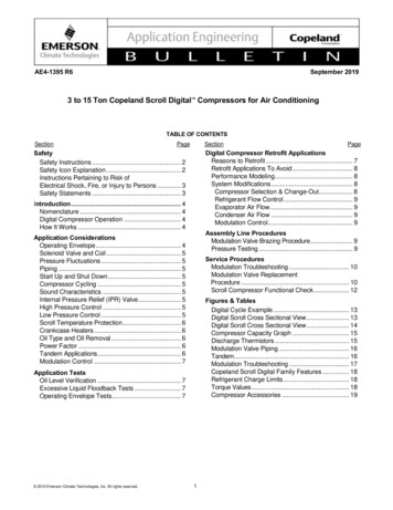
UnitDisplacement@ 50 lpower 5.0Medium temperature standardZXMY-020EZXMY-030EZXMY-040E R454A, R454C& 18.83.425.056.588.7710.0511.6Medium temperature DigitalZXDY-030EZXDY-040ER454A, R454CZXDY-050E& 8.6510.111.4PSPShigh side low side(bar)(bar)28.821Table 1: ZX condensing unit technical dataUnitOuter dimensionslength/width/height withclosed cover (mm)Net weight(kg)FannumberLiquidreceiver size(litres)14.125.914.125.9Medium temperature 60EZXMY-075E424 / 1027 / 840424 / 1029 / 1244767991108112118Medium temperature 5E424 / 1027 / 840424 / 1029 / 124482104108112118Table 2: ZX condensing unit featuresThe figures hereafter show the overall physical dimensions of the ZX condensing units in millimetres:Figure 1: Dimensions of models ZXMY-020E to ZXMY-040E and ZXDY-030E (single-fan units)4AGL Unit ZX A2L E Rev00
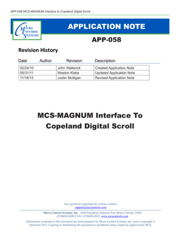
Figure 2: Dimensions of models ZXMY-050E to ZXMY-075E and ZXDY-040E to ZXDY-075E (dual-fan units)2.4Product nameplateThe condensing unit nameplate shows model designation and serial number, as well as locked rotoramps, maximum operating current, safety pressures and weight.The compressor has its own nameplate with all electrical characteristics.2.5NomenclatureThe model designation contains the following technical information about the condensing unit:Figure 3: Nomenclature ZX unitsAGL Unit ZX A2L E Rev005
2.6Application range2.6.1 Qualified refrigerants and oilsQualifiedrefrigerantsQualifiedservicingoilsOil chargein litresR454A, R454C & R455AEmkarate RL 32 3MAFMobil EAL Arctic MY-075E1.241.771.85Table 3: Qualified refrigerants and oilsNOTE: R454A, R454C and R455A are classified as A2L (mildly flammable) refrigerants.NOTE: ZXDY units are equipped with an oil separator. The separator is pre-charged with0.5 litre of oil.2.6.2 Application limitsFor application envelopes, please refer to the compressor application envelopes which can be foundin Copeland brand products Select software, available at www.climate.emerson.com/en-gb.ZX condensing units can be used at ambient temperatures from -15 to 45 C. For lower ambienttemperatures please contact your local Application Engineering representative.2.7BOM variationsThe BOM (bill of material) number at the end of the unit designation indicates the different unit layoutsand details. The ZX units covered in these guidelines are available in the following BOM versions:BOMFamilyIntroductiondateController Y10/202010/2020XCM25D (Emerson - Dixell)XCM25D (Emerson - Dixell)NoYesNoNoTable 4: BOMNOTE: These guidelines are of application only for BOM 304 and 454.6AGL Unit ZX A2L E Rev00
2.8P&I diagrams2.8.1 ZXMY unitsFigure 4: P&I diagram for ZXMY unitsPosition1234567PSH (S1)PTL (B1)PTH (B2)TT1 (B3)TT2 (B6)DescriptionHigh-efficiency Copeland scroll compressorCondenser with 1 or 2 fansLiquid receiverFilter drier / sight glass combinationExpansion device for suction line injectionService valve, suction lineService valve, liquid lineFixed high-pressure switchSuction pressure sensor, low pressurePressure sensor, high pressureDischarge temperature sensorAmbient temperature sensorCommentsSystem safetyCompressor setpointFan speed controlCompressor safetyAdditional functionsFast accessmenuP1PP2PP3tP6tTable 5: Legend of the P&I diagram for ZXMY unitsAGL Unit ZX A2L E Rev007
2.8.2 ZXDY unitsFigure 5: P&I diagram for ZXDY unitsPosition12345678Y1PSH (S1)PTL (B1)PTH (B2)TT1 (B3)TT2 (B6)DescriptionHigh-efficiency Copeland scroll compressor(YBD* for Digital)Oil separatorCondenser with 1 or 2 fansLiquid receiverFilter drier / sight glass combinationService valve, liquid lineService valve, suction lineCrankcase heaterDigital solenoidFixed high-pressure switchSuction pressure sensor, low pressurePressure sensor, high pressureDischarge temperature sensorAmbient temperature sensorCommentsFast accessmenuPre-charged with 0.5 LSystem safetyCompressor setpointFan speed controlCompressor safetyAdditional functionsP1PP2PP3tP6tTable 6: Legend of the P&I diagram for ZXDY units8AGL Unit ZX A2L E Rev00
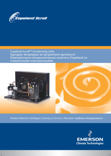
2.9Main components description2.9.1 CompressorUnit modelCompressor modelMedium temperature EYB36K1E-TFMNZXME-075EYB45K1E-TFMNMedium temperature 075EYBD45K1E-TFMNTable 7: Compressor models cross reference2.9.2 Condenser fan(s)The condensers of the ZX condensing units are equipped with single-phase fans.Condensing unitsMedium temperatureStandardNr. of fans(pcs)DigitalFanspeed(rpm)Diameter(mm)Voltage(V / ph / EZXMY-075EZXDY-075E830450380 - 420 V /1 Ph / 50 Hz2230Table 8: Condenser fans technical data2.9.3 HousingZX condensing units with BOM 304 & 454 havespecific housing features: Controller-window in the cabinet door. Thewindow is IP54. It shows the current valueof the electronic controller. The main power switch is installed on thecabinet door and allows to de-energize theunit without opening the cabinet door. Toopen the door the main power switch mustbe in off position. The quick-locks allow for easy and quickopening of the cabinet door by means of thecabinet key. The cabinet key is delivered with the unit. Itis attached to one of the piping connectionsby means of a cable strap.Figure 6: ZX unit housingAGL Unit ZX A2L E Rev009
2.10 XCM25D Electronic controller – FeaturesThe XCM25D controller is designed to be a powerful, flexible controller for use in multipleapplications. It has been developed for condensing units and allows the adjustment of all relevantparameters by the user.2.10.1 DescriptionWARNINGElectrical pins under voltage! Electrical shock hazard! There are unusedfast-on pins (C1 & DO2) on the XCM25D which could be under voltage. Theyare covered by insulated fast-on flags in the factory. Handle carefully whenremoving insulating flags during service on site.The controller is designed for usage in an outdoor refrigeration unit. It is rated to be used for thefollowing environment: Outdoor ambient temperature for controller operation: -40 to 60 C Ambient temperature for storage: -40 to 80 C Maximum humidity: 90 % at 48 C (non-condensing) Board power: 24 VAC 15 %/-20 % Voltage sensing capabilities - Three phase: 200-240, 380-460, 575 VAC 10 %The units of measure are selectable. The factory default unit is bar (always considered relative) forpressure and C for temperature.Figure 7: XCM25D Electronic controller2.10.2 FunctionalitiesThe controller allows for easy commissioning by the technician with the factory settings at the highestprogram level. It also offers the possibility to make substantial changes to the system optimization infurther programming levels. Advanced functionalities can also be activated.The following functions are covered by the controller: Condensing unit control Case control Condenser fan control Defrost Voltage and current sensing (compressor protection) System EXV control Digital compressor control Modbus/Canbus communicationNOTE: The XCM25D controller includes all the functions necessary for the control of the ZXunits. For additional functionalities please contact your local Application Engineeringrepres
AGL_Unit_ZX_A2L_E_Rev00 3 2 Product description 2.1 General information about Copeland EazyCool ZX condensing units Emerson has developed the Copeland EazyCool ZX outdoor condensing unit of second generation